R E S E A R C H
Open Access
Practical decentralized high-performance
coordinated beamforming for both downlink and
uplink in time-division duplex systems
Enoch Lu
*and I-Tai Lu
Abstract
Coordinated beamforming (CBF) has been studied in hope of mitigating the inter-cell interference experienced by cell-edge users. Unfortunately, due to the limitations and/or impracticalities of the proposed designs, the expected performance gains have yet to be realized. Relying on channel soundings from the users and equivalent channel soundings from the cell sites (all on the same frequency), both downlink and uplink decentralized frameworks (and various example designs) are proposed in this paper for the practical transceiver and signaling design of aK-pair system desiring to employ CBF. Remarkably, the proposed singular value decomposition (SVD) example design for both frameworks is equivalent to acentralizedinterference alignment (IA) design. Furthermore, three other proposed design examples achieve better bit error rate, mean square error, and sum capacity performances than the proposed IA-equivalent SVD example design, respectively. In addition, higher sum capacities than the generalized iterative approach, a centralized minimum mean square error CBF design, are numerically observed. Clearly, practical CBF designs which can deliver the expected performance gains are finally available.a
Keywords:Channel sounding; Coordinated beamforming; Coordinated multipoint; Interference alignment; Network MIMO; TDD
1. Introduction
Coordinated multipoint transmission/reception (CoMP) [1-3] is currently attracting a lot of attention (e.g., in Long Term Evolution-Advanced (LTE-A)). It, being based on network multiple-input and multiple-output (MIMO), has multiple cell sites that coordinate their transmissions or receptions (intra-site CoMP can involve only one cell site but this technicality is ignored here for the sake of clarity). If successfully implemented, CoMP can mitigate the inter-site interference, e.g., the inter-cell interference experienced by cell-edge users. In addition, it can improve the coverage and spectral efficiency of the next generation cellular systems [1]. Based on [3], CoMP is divided into four types: joint transmission, dy-namic cell selection, coordinated scheduling, and coordi-nated beamforming (CBF). CBF, the type studied in this paper, has the involved cell sites that coordinate their transmissions/receptions and transceiver designs in order
to minimize the inter-site interference experienced by their users (each user’s data comes from or goes to only one of the cell sites). The coordination of the multiple cell sites must not incur too high of a load on the network. Yet it must provide the desired performance. Thus far, no scheme has achieved this difficult goal. On the contrary, the gap between gains envisaged with perfect channel feedback (in academia and industry) and with practical feedback schemes remains high [4]. So, the search con-tinues for a practicalandhigh-performing CoMP scheme.
There are four fundamental reasons why most of the proposed CBF designs are impractical. Firstly and most importantly, the vast majority of the proposed CBF de-signs, in comparison with their said benefits, require too much information exchange between the nodes. Many of the proposed designs assume that a central processing unit has full perfect channel state information (CSI) and performs the entire transceiver design (e.g., [5-7]). Others assume that some type of iterative process can occur between the cell sites and/or the users (e.g., [8-10]). All in all, most designs assume that a large * Correspondence:[email protected]
Department of ECE, Polytechnic Institute of NYU, 6 Metrotech Center, Brooklyn, NY 11201, USA
amount of information (whether it be CSI, precoders, decoders, etc.) can be transported through the network. This is especially true with regard to the CSI if the sys-tem is frequency-division duplex (FDD) in nature.
Secondly, many of the proposed CBF transceiver de-signs are too complex. Due to the number of design var-iables and the coupling between them, the majority of the designs are iterative in nature (e.g., [5-11]). Though some have proofs of convergence, there is generally no guarantee of how many iterations (equivalently, time) are needed. As the channels are time-varying, this is highly undesirable. Thirdly, many of the designs do not decouple the transceiver designs of the cells involved. Their designs for one cell’s (a cell site and its user(s)) pre-coder(s) and depre-coder(s) are generally heavily dependent on the modulation coding schemes (MCS), number of data streams, transmit powers, etc. of the other cells. This can greatly complicate the schedulers. Last but not the least, most of the designs are done using an average total power constraint per transmitter (e.g., [5,6,8-11]). Since in practice, each antenna is connected to its own power amplifier, this is not sufficient; the instantaneous power per antenna must be adequately constrained.
In this work, both downlink and uplink frameworks (and various example designs) are proposed for the prac-tical transceiver and signaling design of aK-pair system desiring to employ CBF (the downlink framework has been partially presented in [12]). Relying on channel soundings from the users and equivalent channel sound-ings from the cell sites -all on the same frequency (pos-sible in time-division duplex (TDD) systems) - both frameworks are able to overcome the four critical issues listed above. Firstly, the frameworks are decentralized and require a low amount of information exchange. Nei-ther central processing unit is used nor is Nei-there any ex-plicit feedback or feed-forward of CSI, precoders, and decoders; each node obtains all the CSI it needs from the channel soundings/equivalent channel soundings. Each node designs its own precoder or decoder. Further-more, time synchronization of the cells is essentially only needed for the initial channel sounding.
Secondly, the frameworks’ transceiver designs at each cell site and user are of a low complexity. At a cell site, the transceiver designs consist of only two steps: (a) using a singular value decomposition (SVD) to form the nulling portion of the precoder or decoder (the nulling action is essentially a block diagonalization [13] of the overall system channel matrix) and (b) applying a single-user MIMO closed-form solution. At a single-user, they are even simpler - apply a single-user MIMO closed-form solution. Thirdly, the frameworks completely decouple the transceiver designs of the different pairs. It is proved that its design for a pair does not depend on the MCSs, number of data streams, transmit powers, etc. of the
other pairs. Lastly, the frameworks allow limits to be imposed on the instantaneous transmit power of each antenna.
Even though the proposed frameworks are practical, their performances are comparable to those which are not. It is proven that one of the proposed example de-signs (specifically, the SVD design) for both frameworks is equivalent to acentralizedinterference alignment (IA) design. Furthermore, it is shown numerically that three other proposed examples achieve better bit error rate, mean square error, and sum capacity performances than the proposed IA-equivalent SVD example, respectively. In addition, higher sum capacities than the generalized iterative approach, a centralized minimum mean square error (MMSE) CBF design, are numerically observed for some proposed examples. Clearly, here are practical low-information exchange overhead CBF designs which are able to deliver the long-awaited performance gain.
There are other CBF schemes in the literature which result in zero inter-site interference. They are however, to the best of our knowledge, significantly different from our proposal. For example, the papers with single an-tenna receivers (e.g., [7,9]) do not need a decoder. The papers with all multiantenna nodes (e.g., [14] and other IA schemes) run into the four practicality issues dis-cussed before. Lastly, the vast majority of them are purely transceiver designs - they do not consider signal-ing as is done here.
We have one last introductory comment. The strong aspects of this work are in the practical side: the local channel information (obtained via sounding in TDD mode) is adequate, and each cell site can construct its precoder and decoder locally without further informa-tion exchange among different cell sites and users. How-ever, the practicality of the proposed approach may be reduced if some practical challenges faced in a large scale network (such as many antennas, a lot of users, channel estimation error, and block diagonalization error) cannot be properly addressed. Fortunately, the new developments on cloud-radio access network (C-RAN), massive MIMO, spatial user scheduling, etc., have addressed a lot of these practical issues and have helped to demonstrate the im-portance and timeliness of this work. These practical chal-lenges and their possible solutions will be briefly discussed in the Conclusions section.
The notation of this paper is as follows. All boldface letters indicate vectors (lower case) or matrices (upper case).A′, A, A*, tr(A), E(A), and rank(A) stand for the transpose, conjugate, conjugate transpose, trace, expect-ation, and rank of A, respectively. λmax(A) denotes the largest eigenvalue ofA. [a]idenotes theith element ofa.
diag […] denotes the diagonal matrix with elements […] on the main diagonal. Ir signifies a r×ridentity matrix.
denotes that A is a positive definite matrix. (a)+ ≜ max (0,a).CN(μ,σ2) denotes a complex normal random variable with meanμand varianceσ2.
2. Proposed frameworks
2.1. System model
The system considered has Kcell site-user pairs; thekth
cell site and user only want to send data to each other (k= 1,…,K). Thekthcell site andkth user havebkand uk
antennas, respectively. It is assumed that bk>ul, ∀k, ∀l.
Since the cell sites have more antenna elements than the users, the cell sites will carry out the interference mitiga-tion task for both downlink and uplink scenarios in the proposed frameworks.
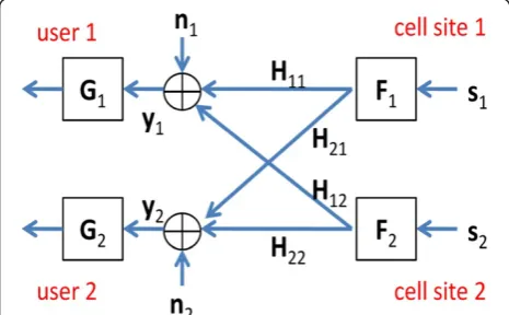
In the downlink scenario (see Figure 1), the received signal vector at thekthuser is given by
yk¼HkkFkskþ
XK
l¼1;l≠k
HklFlslþnk: ð1Þ
There aremkdata streams for thekthpair wheremk≤uk.
The source (data) to be transmitted from thekthcell site to thekthuser,sk, ismk× 1 and is characterized by its positive
definite source covariance matrix,Φsk ¼E sksk
¼σ2
skImk; sk is precoded by Fk, the bk×mk precoder, and then
transmitted. The channel from the kth cell site to the
lth user is ul×bk and is denoted by Hlk. The noise
vector, nk, is uk× 1 and is characterized by its noise
covariance matrix, Φnk¼EðnknkÞ ¼βkIuk. The sources and noises of different nodes are all independent of each other and zero-mean. Once the kth user receives yk, it
applies its mk×uk decoder, Gk, to process the received
vector.
The notation and definitions for the uplink scenario (see Figure 2) are analogous to those for the downlink. An underline ‘_’ is added below the downlink variables to obtain the corresponding uplink ones. For convenience,
we will also denote the antenna numbers at the cell site and the user asbk anduk, respectively. Thus, the receive
signal vector is
yk¼HkkFkskþ XK l¼1;l≠k
HklFlslþnk; ð2Þ
where sl, Φsl¼σsl2Im
l, ml (ml≤ul<bl) and Fl are the source vector, source covariance matrix, number of data stream, and precoder of the lth user, respectively; nk,
Φnk¼βkIb k, and Gk are the noise vector, noise
covari-ance matrix, and decoder of the kth cell site; and Hkl is
the uplink channel matrix from the lth user to the kth
cell site. Note that the downlink and uplink channels are reciprocal, i.e., Hkl¼H0lk;∀k;∀l:
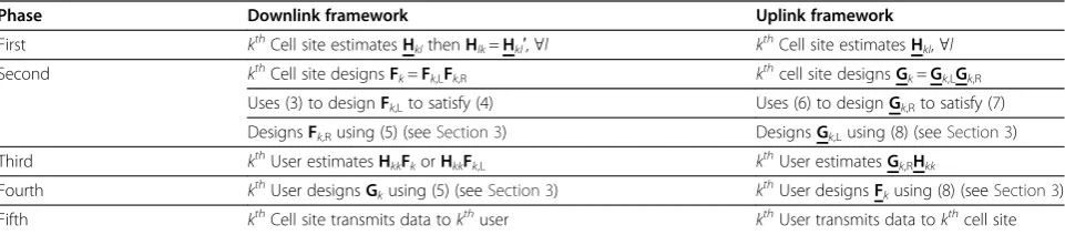
2.2. Proposed framework for the downlink scenario The proposed framework has five phases. In the first phase, the users perform channel soundings so that each cell site can estimate its reverse channels, i.e., so that the
kth cell site can estimate Hkl, ∀l. Due to reciprocity, the kth cell site can thus have an estimate of Hlk¼H0kl;∀l. In the second phase, each of the cell sites uses its chan-nel estimates to design its own precoder. The kth cell site designs its precoder Fk=Fk,LFk,R by first designing its bk×dk left precoder Fk,L for inter-pair interference mitigation and then its dk×mk right precoder Fk,R for performance enhancement. The parameter dk denotes
the maximum number of data streams allowed for the
kth pair where both intra-data-stream and inter-pair interference can be mitigated (see feasibility condition in (23a)).
To avoid the intra-data-stream interference for the kth
pair, we need bk≥dk≥mk. The condition required for
mitigating the inter-pair interference is a bit more com-plicated. Here, we choose for the kth cell site the dk
Figure 1Downlink scenario (only two pairs are shown).
columns ofFk,Lto be an orthonormal basis for the null
full rank. This restriction to the antenna setup due to the need for dkto be greater than or equal tomkis
dis-cussed in more detail in the section on feasibility condi-tions, in Section 4.2.
Since each cell site picks its left precoder in this way, the nulling constraint,
HlkFk ¼0; ∀l≠k; ð4Þ
is satisfied for any Fk,R because HlkFk=HlkFk,LFk,R=
(HlkFk,L)Fk,R=0Fk,R=0, ∀l≠k. There will be no
inter-pair interference at the users (note that the receiver pro-cessing is not taken into account when calculating the null space because we want to minimize the signaling load).
From the perspective ofFk,R, the entire system is sim-ply a single-user MIMO system where Fk,R and HkkFk,L are the equivalent precoder and channel matrix, respect-ively. Using the nulling constraint in (4), (1) reduces to
yk¼HkkFkskþnk¼ HkkFk;L
Fk;Rskþnk: ð5Þ
Using HkkFk,L, the kth cell site will thus design Fk,Rto optimize its own link subject to some power constraint onFk. In addition toHkkFk,L, the noise covariance matrix
Φnk ¼E nknk
of the kth user may also be employed in the design ofFkif its estimate is available at thekth cell
site (see Section 3).
In the third phase, each of the cell sites performs an equivalent channel sounding with either its designed precoder or left precoder. The reason why there are two choices is to allow two different decoder designs.
Depending on which case, the kth user can estimate HkkFk or HkkFk,L. With HkkFk, the kth user can design
the MMSE decoder while withHkkFk,L, it can design the
SVD one. Since the designed precoder causes no inter-ference to the other users, this and the final two phases do not need synchronization among the pairs. Further-more, orthogonal pilots are not needed in this phase. In the fourth phase, each user uses its noise covariance matrix Φnk and the estimate of HkkFk or HkkFk,L from phase 3 to design its decoderGk(see Section 3). Once
fin-ished, the fifth and final phase, the data transmission, can now occur. The five phases are summarized in Table 1.
2.3. Proposed framework for the uplink scenario
The proposed framework for the uplink scenario also has five phases. In the first phase, the users perform channel soundings so that each cell site can estimate its channels, i.e., so that the kth cell site can estimate Hkl,
∀l. In the second phase, each of the cell sites uses its channel estimates to design its own decoder. In particu-lar, the kth cell site partitions its decoder Gk=Gk,LGk,R where the dk×bk right decoder Gk,R is employed for inter-pair interference mitigation and themk×dkleft
de-coder Gk,Lfor the performance enhancement. The par-ameter dk denotes the maximum number of data
streams allowed for the kth pair where both intra-data-stream and inter-pair interference can be mitigated (see feasibility condition in (23b)).
To avoid the intra-data-stream interference for the kth
pair, we need bk≥dk≥mk. For mitigating the inter-pair
interference, we choose for the kth cell site the dk rows
of its right decoder Gk,R to be an orthonormal basis of the left null space for
Ak ¼ Table 1 Five phases of the proposed frameworks
Phase Downlink framework Uplink framework
First kthCell site estimatesHklthenHlk=Hkl′,∀l kthCell site estimatesHkl,∀l
Second kthCell site designsF
k=Fk,LFk,R kthcell site designsGk=Gk,LGk,R
Uses (3) to designFk,Lto satisfy (4) Uses (6) to designGk,Rto satisfy (7)
DesignsFk,Rusing (5) (seeSection 3) DesignsGk,Lusing (8) (seeSection 3)
Third kthUser estimatesH
kkFkorHkkFk,L kthUser estimatesGk,RHkk
Fourth kthUser designsG
kusing (5) (seeSection 3) kthUser designsFkusing (8) (seeSection 3)
This restriction to the antenna setup due to the need for
dkto be greater than or equal tomkis discussed in more
detail in the section on feasibility conditions, Section 4.2. Since each cell site picks its right decoder in this way, the nulling condition
pair interference at the cell sites after the right decoders (note that the transmitter processing is not taken into ac-count when calculating the null space because we want to minimize the signaling load).
After decoding byG―k;R, (2) becomes
For the kth pair, the entire system simply becomes a single-user MIMO system where G―k;L, G―k;Ryk, G―k;RHkk,
andG―k;Rnk are the equivalent decoder, received signal vec-tor, channel matrix, and noise vecvec-tor, respectively. Given Gk,R, its estimate ofHkk, and its estimate ofΦnk, thekthcell
site thus designs its left decoderGk,L(see Section 3). In the third phase, each of the cell sites performs an equivalent channel sounding using the transpose of its designed right decoder so that its user can estimate the equivalent channel, i.e., so that thekthuser can estimate Gk,RHkk. Note that due to the nature ofGk,R, this
equiva-lent channel sounding causes no interference at usersl,
∀l≠k, and does not have to be synchronized with that of the other pairs. Furthermore, orthogonal pilots are not needed here. In the fourth phase, each user uses its esti-mate of the equivalent channel from phase 3 to design its precoder subject to some power constraint (the kth
user uses Gk,RHkk to design Fk). In addition to Gk,RHkk,
the kth user may also use an estimate of the equivalent noise covarianceE G―k;RnknkG―k;R
¼G―k;RΦnkG―k;R¼βkIdk (if available) in its design of Fk (see Section 3). Once
finished with the fourth phase, the fifth and final phase, the data transmission, can now occur. The five phases for the uplink are summarized in Table 1.
3. Example precoder-decoder designs
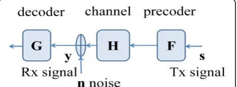
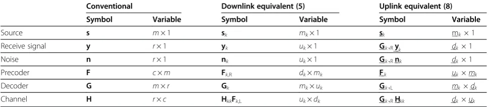
3.1. Conventional and equivalent single-user MIMO systems As mentioned in Section 2, the nulling constraint (4) (or (7)) decouples the K-pair system into K-independent equivalent single-user MIMO systems as described by (5) for the downlink (or (8) for the uplink). The remaining tasks are to design the precoder and decoder of each equivalent single-user MIMO system for facili-tating efficient data transmission. In this subsection, we will compare a conventional single-user MIMO system (shown in Figure 3) with the equivalent single-user
MIMO systems for both downlink and uplink scenarios. Firstly, the corresponding variables for the conventional and equivalent single-user MIMO systems are listed in Table 2. Secondly, differences with respect to power con-straints and noise covariance will be discussed.
Regarding the power constraints, there exists no differ-ence between the conventional and uplink equivalent single-user MIMO systems; but there appears to be some difference between the conventional and downlink equivalent single-user MIMO systems. The average total power (ATP) constraint for the conventional single-user MIMO system is
P¼trfEðFssFÞg ¼trfFFgσ2s: ð9aÞ
The constraint is named as such because it constrains the average power, tr{E(Fss*F*)}, toP. Likewise, the ATP constraint for the downlink equivalent single-user MIMO system is
The downlink equivalent single-user MIMO system, however, is not the original downlink system. Does (9b) really constrain the ATP of the kth cell site to Pk?
Sur-because Fk,L is chosen using (3) and thus guarantees F
k;LFk;L¼Idk: Define
L¼λmaxfEðFssFÞg ¼λmaxfFEðssÞFg
¼λmaxfFFgσ2s: ð11aÞ
The instantaneous array power (IAP) constraint for the conventional single-user MIMO system is
max
It is named as such because it constrains the in-stantaneous sum power of the antenna array (and hence the instantaneous peak power of each antenna) of the transmitter. The physical meanings of L can be understood from the following two special cases. Firstly, if the precoder F is a unitary matrix, one ob-tains from (11a)
L¼σ2s ð11cÞ
which represents the average power of each data stream. Thus, the ATP in (9a) is equivalent to the IAP in (11a) if P = mL when F is unitary. Secondly, if a constant amplitude modulation scheme is used and the system is fully loaded, ss¼mσ2
s, one obtains from (11a) and (11b) as
1
which represents the upper bound of the spatial aver-age of the instantaneous antenna sum power.
From (11a), the IAP constraint for the downlink equivalent single-user MIMO system is
Lk ¼λmax E Fk;RskskFk;R
n o
: ð12Þ
Again, the downlink equivalent single-user MIMO sys-tem, however, is not the original downlink system. Does
(12) really constrain the IAP of the kth cell site to Lk maxsk s Thus, we conclude that the ATP and IAP constraints can also be employed, without any modification, for the downlink equivalent single-user MIMO system. Summa-rized in Table 3 are the ATP and IAP constraints for the conventional and equivalent single-user MIMO systems.
Regarding the noise covariance, there exists no differ-ence between the conventional and downlink equivalent single-user MIMO systems. But there appears to be some difference between the conventional and uplink equivalent single-user MIMO systems. The noise covari-ance is E(nn*) =βIfor the former and EðGk;RnknkGk;RÞ
for the latter. However,
Gk;RΦnkGk;R¼βkGk;RGk;R¼βkIdk ð14Þ
because the rows ofGk,Rare chosen to be anorthonormal basis for the left null space ofAkin (6). Applying (14), we
see the noise covariance for both the conventional single-user MIMO system and the uplink equivalent single-single-user MIMO system is just at scalar times an identity matrix. Summarized in Table 3 are the covariance matrices for the conventional and equivalent single-user MIMO systems.
3.2. Example designs
The main conclusion of the previous section and Tables 2 and 3 is that for the ATP or IAP constraints, the down-link and updown-link equivalent single-user MIMO systems
Table 2 Corresponding variables of the conventional and equivalent single-user MIMO systems
Conventional Downlink equivalent (5) Uplink equivalent (8)
Symbol Variable Symbol Variable Symbol Variable
Source s m× 1 sk mk× 1 sk mk1
can be treated as conventional single-user MIMO sys-tems. Thus, all example designs in this subsection are (a) given using the notation of the conventional single-user MIMO system (F, G, H, etc.) and (b) are applicable to both downlink and uplink equivalent single-user MIMO systems.
Presented here are practical minimum mean square error (PMMSE), practical maximum mutual information (PMMI), practical minimum symbol error rate (PMBER), and practical SVD (PSVD) designs for the precoder and decoder. Each design is subject to either the ATP or the IAP constraint. The word ‘practical’ is used as a re-minder that these designs are for the proposed practical decentralized downlink and uplink frameworks which have been discussed in Section 2 and summarized in Table 1. Based on Figure 3 and Tables 2 and 3, the four design approaches are outlined in Table 4.
The first three approaches (PMMSE, PMMI, or PMBER) in Table 4 are formulated as optimization prob-lems. The cost functions of PMMSE and PMMI are mean square error (to be minimized) and mutual infor-mation (to be maximized), respectively. The PMBER ap-proach maximizes for each pair a lower bound for the
minimum distance between symbol hypotheses and is an approximate alphabet-independent minimum bit error rate (BER) design. For the PMMSE design subject to ATP or IAP constraint (denoted as PMMSE-ATP or PMMSE-IAP, respectively), the solution can be readily obtained by applying Lemma 1 or 3 of [15]. Similarly, Lemmas 2 and 4 of [15] can be applied for the PMMI-ATP and PMMI-IAP problems, respectively, and Lemmas 5 and 6 of [15] for the PMBER-ATP and PMBER-IAP problems, respectively. The closed-form solutions of these three approaches are provided in [15] and summarized in Appendix for the convenience of the readers.
Not only these closed-form solutions are optimum for their respective problems in Table 4 (see proofs in [15]), they also fit perfectly into the proposed frameworks. The only requirement which is not met is that the transmit-ter (i.e., the cell site for the downlink scenario or the user for the uplink scenario) needs an estimate of the noise covariance of the receiver, which increases the net-work load. As such, some systems may prefer to use other closed-form solutions instead. One such option is to adopt the PSVD approach (the last design listed in Table 4) where the transmitter does not need to know
Table 4 Four designs of precoder F and decoder G subject to either ATP or IAP constraint
Approaches for designing precoder F and decoder G Constraint
PMMSE min singular values are in decending order
ð Þ
ATP (9a)
IAP (11a)
Table 3 Covariance matrices and ATP and IAP constraints of conventional and equivalent single-user MIMO systems
Conventional Downlink equivalent (5) Uplink equivalent (8)
the noise covariance of the receiver. In PSVD, the preco-der and decopreco-der can be preco-derived directly by performing SVD of the channel (as shown in Table 4):
F¼α½t1…tm; G¼W
withα2¼P=mσ2
sðfor ATPÞ;α2¼Lσ2sðfor IAPÞ ð15Þ
In (15), vectors t1…tm and matrix W are given in
Table 4. The PSVD-ATP and PSVD-IAP only differ in theαs they use. If L = P/m, the twoαs are the same and thus the PSVD-ATP and PSVD-IAP are thesame. Alter-natively, instead of using the SVD decoder in (15), the MMSE decoder in (29) can also be employed for the PSVD approach. Note that the decoder is designed at the receiver. Thus, in this case, the transmitter still does
notneed to estimate the noise covariance, unlike in the other three approaches in the Appendix.
4. Properties of proposed approach
4.1. Optimality
In the following, the optimality of the PMMSE solution for the downlink and uplink frameworks will be proven. The optimality of PMMI and PMBER results can be established following the same procedure and are there-fore omitted. Consider the downlink equivalent single-user MIMO system first. The MMSE cost function and the power constraint are (from Tables 2,3,4)
min
Note that (18) and (19) define the PMMSE problems for thekthpair data transmission in the downlink frame-work. Since Fk,L has been determined previously for
inter-pair interference cancellation and is known, the
optimal solution {Gk,Fk,R} for the downlink equivalent
problem in (16) and (17) (see [15]) can be used to con-struct the optimal decoder and precoderfGk;FkgFk¼Fk;LFk;R of thekth pair in the downlink framework. Next, consider the uplink equivalent single-user MIMO system. The cost function and the power constraint are
min
Note that (22) and (21) define the PMMSE problems for the kth pair data transmission in the uplink frame-work. Since Gk,R has been determined previously for
inter-pair interference cancellation and is known, the optimal solution {Gk,L,Fk} for the uplink equivalent
problem in (20) and (21) (see [15]) can be used to con-struct the optimal decoder and precoder {Gk=Gk,LGk,R,
Fk} of thekthpair in the uplink framework.
4.2. Feasibility conditions
Regardless of which scenario, the kth pair’s data trans-mission will only be feasible if its equivalent channel (HkkFk,L in downlink and Gk,RHkk in uplink) has
suffi-cient rank. The goal of this subsection is thus to derive necessary and sufficient conditions for
rank HkkFk;L Data transmission for the kth pair is feasible in the downlink framework if and only if it is feasible in the up-link framework. The reason is twofold. First, since Ak=
Without loss of generality, let 0 <mk≤uk and, let
Ak and HkkFk,L be full rank. By observing that (23a) holds if and only if dk≥mk and by applying the rank
nullity theorem, the necessary and sufficient condition for (23a),
bk−mk≥
XK
l¼1;l≠kul; ð24aÞ
is obtained. Interestingly, the feasibility of data trans-mission depends solely on the number of antennas and data streams - not on the particular Fk,L chosen or the channel realization (assuming Ak and HkkFk,L be full rank). Similarly, the necessary and sufficient condition for (23b) is
bk−mk≥
XK
l¼1;l≠kul; ð24bÞ
4.3. Equivalencies between downlink and uplink frameworks
Letmk=mk,Φsk ¼Φsk¼σ2skImk,Φnk¼βkIuk,Φnk ¼βk Ibk, and let (24a) and (24b) hold. Also, let both down-link and updown-link be under the same ATP or IAP. Then, there are actually equivalencies between the perfor-mances of the downlink and uplink frameworks for the
kthpair:
a) LetGk;R¼F0k;Land one of the optimum
closed-form solutions in (29) to (34) is employed. If thekth pair uses the same solution for both downlink and uplink, its downlink and uplink mean square error (MSE) per stream, signal to interference and noise (SINR) per stream, and mutual information are the same.
b) For a given power constraint (ATP or IAP), the lowest achievable sum MSE (derived from PMMSE) and highest achievable mutual information (derived from PMMI) for thekthpair are the same for the downlink and uplink frameworks.
Here is a rough sketch of the proof. When the optimum closed-form solutions in (29) to (34) are used, the MSE per stream, SINR per stream, and mutual infor-mation are essentially functions of only the eigenvalues of the matrix Ξ in (28). With appropriate variable map-pings, this matrix is
Ξk¼β−1k Fk;LHkkHkkFk;L; ð25aÞ
Ξk¼β−1k Hkk
Gk; R Gk;
RHkk
¼β−1k Hkk Fk ;LF 0
k;LH 0
kk; ð25bÞ
for the downlink and uplink frameworks, respectively. In (25b), Gk;R¼F
0
k;L and Hkk¼H
0
kk have been employed.
AsΞkand Ξk have the same non-zero eigenvalues,‘point (a)’ follows because the MSE per stream, SINR per stream, and mutual information are functions of these non-zero eigenvalues. ‘Point (b)’ can be proved from point (a) and the fact that solutions (29) to (34) are optimum in their respective sense (see Table 4 and the proofs in [15]).
4.4. Equivalencies among some optimal solutions
Consider the downlink scenario (the uplink scenario is analogous and is omitted). It has been shown in (A4) that PMMSE-IAP and PMMI-IAP are equivalent (i.e., they have the same precoder and decoder). It has also been shown in that if the power constraint parameters in (9a) and (11a) are related byL = P/m, the PSVD-ATP and PSVD-IAP are equivalent. Interestingly, if the MMSE decoder is employed for PSVD approach and Φnk¼βkIuk, the PMMSE-IAP, PMMI-IAP, and PSVD-IAP are equivalent for any Lk. Thus, if Lk= Pk/mk,
Φnk¼βkIuk and the MMSE decoder is employed for PSVD approach, the PMMSE-IAP, PMMI-IAP, PSVD-IAP, and PSVD-ATP are equivalent. When there is only one data stream per pair, PMMSE-ATP, PMMI-ATP, and PMBER-ATP are exactly the same (sinceΛin (28) is just a scalar in this case, (30), (32), and (34) will all yield the sameΩin (29)). When in addition, Φnk ¼βkIuk and the MMSE decoder is employed for PSVD approach, PSVD-ATP is also MMSE and max information rate. These equivalencies (summarized in Table 5) can be derived, with some work, using (28) and the closed-form solutions for the PMMSE-IAP and PMMI-IAP problem.
4.5. Relationship to interference alignment
Firstly, we will show that some of our example designs satisfy the IA conditions. In the downlink scenario (the uplink scenario is analogous and is omitted), a set of precoders {Fk} and decoders {Gk} achieve IA [16] when
rankðGkHkkFkÞ ¼mk; ð26aÞ
GkHklFl¼0;∀l≠k;∀k: ð26bÞ
Let (24a) hold for every pair. Looking at the downlink framework, one can easily see that all of its
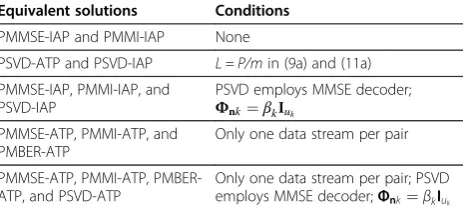
Table 5 Equivalencies among various optimal solutions
Equivalent solutions Conditions
PMMSE-IAP and PMMI-IAP None
PSVD-ATP and PSVD-IAP L = P/min (9a) and (11a)
PMMSE-IAP, PMMI-IAP, and PSVD-IAP
PSVD employs MMSE decoder; Φnk¼βkIuk
PMMSE-ATP, PMMI-ATP, and PMBER-ATP
Only one data stream per pair
PMMSE-ATP, PMMI-ATP, PMBER-ATP, and PSVD-ATP
implementations satisfy (26b); the left precoders result in AkFk=0, ∀k, or equivalently HklFl=0, ∀l≠k, ∀k. In
addition, one can easily see that some of its implementa-tions (e.g., PSVD-ATP in Section 3.2) satisfy (26a). As a result, constructive proofs are obtained for the feasibility of IA in the downlink scenario when (26a) holds for every pair. Thus, the PSVD-ATP is an IA-equivalent implementation.
Secondly, we will show that an IA solution satisfies the nulling constraint of our schemes when each pair’s num-ber of data streams is equal to its user’s number of an-tennas, i.e., mk=uk. With mk=uk, any {Fk,Gk} which
achieves IA must therefore satisfy (a) (26a) ∀k; (b) Gk−1
exists,∀k; and finally (c) the nulling constraintHklFl=0,
∀l≠k,∀k(equivalentlyAkFk=0,∀k).
Finally, the example transceiver designs in Appendix are optimal for their metrics under their power con-straints and nulling concon-straints AkFk=0, ∀k. However,
the IA-equivalent implementation (such as PSVD) is not designed under those criteria and conditions and, there-fore, may not be optimal. Thus, the performance of an example transceiver design in Appendix will be at least as good as that of the IA-equivalent PSVD design for its given metric and power constraint, e.g., the PMMSE-ATP will obtain a MSE at least a small as the MSE of the IA-equivalent PSVD design (see [5,16]). On the other hand, the example designs in Appendix may not be able to achieve easily what general IA designs can [17,18].
5. Numerical results
To demonstrate the performance of the proposed frame-works, this section presents simulation results for typical CBFK-pair systems under the downlink scenario. The re-sults for the uplink scenario are not presented due to the equivalencies (Section 4.3) and the similarities in the re-sults. Three configurations are considered. In configuration A,K= 2,bk= 4,uk= 2,∀k; in configuration B,K= 2,bk= 8, uk= 4,∀k; and in configuration C,K= 4, bk= 8,uk= 2,∀k.
In configuration A, two cases are considered. In case A-1,
mk= 1, ∀k (partially loaded), and in case A-2, mk= 2, ∀k
(fully loaded). In configurations B and C, only the fully loaded case is presented. Therefore,mk= 4,∀k, in
configur-ation B andmk= 2,∀k, in configuration C. As (24a) is
satis-fied for all cases, data transmission using the proposed framework is always feasible in all of them. No matter for which case, the source covariance matrices are identity matrices. Each data stream consists of uncoded BPSK modu-lated symbols. The noises are independently identically dis-tributedCN(0,ε) random variables andΦnk ¼βkIuk ¼εIuk,
∀k. The channel elements are independently identically distributedCN(0,1) random variables in each case.
For each case, five designs under the ATP condition are considered: the GIA-ATP, PMMSE-ATP, PMMI-ATP,
PMBER-ATP, and PSVD-ATP. For comparison, the PMMSE design under the IAP condition (i.e., PMMSE-IAP) is also included. The MMSE decoder is employed for all designs. The GIA-ATP (see [5]) is a centralized MMSE design and is included as a performance bench-mark. Note that the designs considered here are but a sub-set of the possible implementations. One can derive others using results from [19,20]. The various equivalence relations among different designs under special conditions are discussed in Section 4.4 and summarized in Table 5.
Because PMMSE-IAP’sFk;R¼ i.e., so that the maximum instantaneous antenna power of each cell site is equal to P, the total average power for a cell site under the ATP constraint divided by its number of antennas. Note that the average power under the IAP constraint will thus be upper bounded byP. For the sake of comparison, perfect CSI is used in the GIA-ATP. In addition, no errors are incurred by the channel soundings and the equivalent channel soundings in the proposed designs.
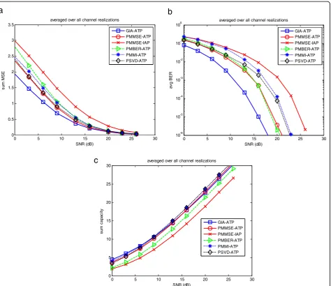
The sum MSEs, system BERs, and sum capacities for case A-1 versus signal-to-noise ratio (SNR)≜10log10(P/ε) are plotted in Figure 4a,b,c, respectively. They are ob-tained by averaging over 15 channel realizations. First, let us look at the sum MSEs of the six designs in Figure 4a. The GIA-ATP and the PMMSE-IAP provide the best and worst performances, respectively. The other four designs result in exactly the same performance (because there is only one data stream per pair and these four results are equivalent; see Table 5). Furthermore, the sum MSEs of all designs is merging together as the SNR increases. The better performance of the GIA-ATP is expected; it is a centralized MMSE design and its precoders do not neces-sarily need to null out the interfering channels. The PMMSE-IAP’s performance is behind the others because its average total power per cell site is less thanP.
Next, let us look at the system BER results. All of the BERs are very good and the performance order of the designs is the same as with the sum MSEs. For the sum capacity results, the designs are still in the same per-formance order. In addition, all of the curves have ap-proximately the same slope. Though the GIA-ATP is a MMSE design, it has the highest sum capacity. This can be attributed to it being a centralized design while the others are distributed. Moreover, the PMMI-ATP cannot do any waterfilling between data streams because there is only one data stream.
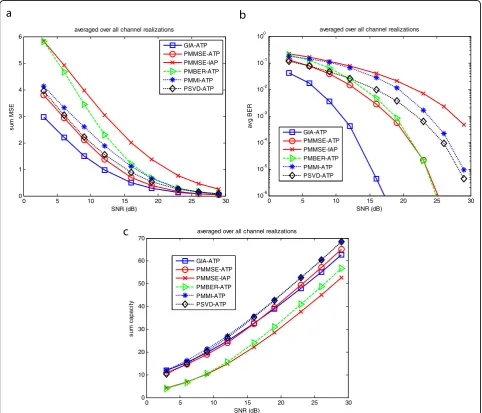
respectively. Since each pair has more than one data stream, the equivalencies between PMMSE-ATP, PMMI-ATP, PMBER-PMMI-ATP, and PSVD-ATP no longer hold. Note that the performance of each of the three example de-signs (PMMSE-ATP, PMMI-ATP, and PMBER-ATP) in Appendix is better than that of PSVD-ATP (the equiva-lent centralized IA design) under its metric and power constraint. Granted, the PMBER-ATP design is using an approximate minimum BER metric. Consequently, it is observed that the PSVD-ATP does slightly outperform it in low SNRs.
First, let us look at the sum MSEs of the six designs. The performance order is, from best to worst, the GIA-ATP, PMMSE-ATP, PSVD-ATP, PMMI-ATP, PMBER-ATP, and PMMSE-IAP. The sum MSEs of all designs is merging to-gether as the SNR increases. Becausemk= 2 andΦnk=εI2,
∀k, the PSVD-ATP is MMSE subject to IAP in (12) with
Lk=P/2, ∀k. There are two interesting remarks: (a) the
optimum performances under ATP in (9b) and IAP in (12) are similar when the average total power of the two are the same and (b) the difference in the performances of the PMMSE-IAP and PSVD-ATP is due to the value ofLkused
in (12).
For the system BER results, the performance order is, from best to worst, the GIA-ATP, PMBER-ATP and PMMSE-ATP, PSVD-ATP, PMMI-ATP, and PMMSE-IAP. Interestingly, the PMBER-ATP, using an approximate mini-mum BER design, provides excellent results. In addition, the PMMSE-ATP, though designed for MSE, provides es-sentially the same BER results as the PMBER-ATP.
For the sum capacity results, the performance order is dependent on the SNR. Among the five decentralized
0 5 10 15 20 25 30
0 0.1 0.2 0.3 0.4 0.5 0.6 0.7 0.8 0.9
s
u
m MS
E
SNR (dB)
averaged over all channel realizations
GIA-ATP PMMSE-ATP PMMSE-IAP PMBER-ATP PMMI-ATP PSVD-ATP
0 5 10 15 20 25 30
10-8 10-7 10-6 10-5 10-4 10-3 10-2 10-1 100
av
g B
E
R
SNR (dB)
averaged over all channel realizations
averaged over all channel realizations
GIA-ATP PMMSE-ATP
PMMSE-IAP PMBER-ATP PMMI-ATP PSVD-ATP
0 5 10 15 20 25 30
2 4 6 8 10 12 14 16 18 20 22
su
m
c
a
p
a
ci
ty
SNR (dB)
GIA-ATP PMMSE-ATP PMMSE-IAP PMBER-ATP PMMI-ATP PSVD-ATP
a
b
c
practical designs, the PMMI-ATP has the largest sum capacity (for all SNRs) because it is designed to maximize the mutual information. The PMMSE-IAP has the smallest sum capacity because its transmitted power is less than that used by other designs under the ATP condition. PMBER-ATP has the second smallest sum capacity because it is designed to maximize only the minimum eigenvalue of the matrix shown in Table 4. Remarkably, the GIA-ATP, though it is a centralized de-sign, does not always have the highest sum capacity. Moreover, two other much simpler decentralized de-signs, PSVD-ATP and PMMSE-ATP, have achieved simi-lar sum capacities as the centralized GIA-ATP. In fact, PSVD-ATP has a slightly larger sum capacity than GIA-ATP and PMMSE-GIA-ATP for high SNRs. This is because PSVD-ATP is equivalent to PSVD-IAP (if Lk=P/2, ∀k)
and, furthermore, PSVD-IAP is equivalent to PMMI-IAP (since mk= 2 and Φnk=ε I2, ∀k). Thus, the PSVD-ATP
is max information rate subject to IAP in (12), i.e., PMMI-IAP, withLk=P/2,∀k.
Note that Figure 4a,b,c presents the single data stream results and Figure 5a,b,c presents the two data stream results. Comparing Figure 4a with Figure 5a, the MSEs in Figure 4a are smaller than half of the sum MSEs (i.e., the corresponding average MSEs over the two data streams) in Figure 5a. Comparing Figure 4b with Figure 5b, the BERs in Figure 4b are smaller than the corresponding average BERs over the two data streams in Figure 5b. Comparing Figure 4c with Figure 5c, the capacities in Figure 4c are larger than half of the sum capacities (i.e., the corresponding average capacities over the two data streams) in Figure 5c. All of the above observations are
0 5 10 15 20 25 30
0 0.5 1 1.5 2 2.5 3 3.5
s
u
m MS
E
SNR (dB)
averaged over all channel realizations
GIA-ATP PMMSE-ATP
PMMSE-IAP PMBER-ATP PMMI-ATP PSVD-ATP
0 5 10 15 20 25 30
10-6 10-5 10-4 10-3 10-2 10-1 100
av
g B
E
R
SNR (dB)
averaged over all channel realizations
GIA-ATP PMMSE-ATP PMMSE-IAP PMBER-ATP PMMI-ATP PSVD-ATP
0 5 10 15 20 25 30
0 5 10 15 20 25 30
su
m
c
a
p
a
ci
ty
SNR (dB)
averaged over all channel realizations
GIA-ATP PMMSE-ATP PMMSE-IAP PMBER-ATP
PMMI-ATP PSVD-ATP
a
b
c
due to the fact that each of the two communication pairs in configuration A is an equivalent 2 by two single-user MIMO system, and the two eigenchannel gains of the equivalent 2 by two single-user MIMO system are usually very different. Thus, one of the two data streams in case A-2 (results presented in Figure 5a,b,c) must go through the eigenchannel with the smaller channel gain. But the single data stream in case A-1 can always use the eigenchannel with the larger channel gain (results pre-sented in Figure 4a,b,c). Thus, the per-stream perfor-mances in Figure 4a,b,c are generally better than those in Figure 5a,b,c.
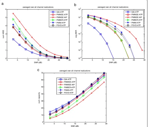
To demonstrate the usefulness of the proposed schemes, we also present the numerical results of the two larger systems. In configuration B, the number of antennas at each user is twice of that in configuration A; in configuration C, the number of users is twice of that
in configuration A. Obviously, the number of antennas at the cell site in configuration B or C needs to be twice of that in configuration A as well. The MSEs, system BERs and sum capacities for configuration B are plotted in Figure 6a,b,c, respectively. In addition, the MSEs, system BERs, and sum capacities for configuration C are plotted in Figure 7a,b,c, respectively. Although the systems are larger, the observations made for configuration A can also be made for configurations B and C. Moreover, comparing Figures 6a or 7a with Figure 5a, the MSEs in Figures 6a or 7a are around twice of the MSEs in Figure 5a. Comparing Figures 6b or 7b with Figure 5b, the BERs in Figures 6b or 7b are slightly larger than the BERs in Figure 5b. Compar-ing Figures 6c or 7c with Figure 5c, the capacities in Figures 6c or 7c are twice of the capacities in Figure 5c. All of the above observations are due to the fact that the system represented by Figure 6a,b,c or by Figure 7a,b,c is
0 5 10 15 20 25 30
0 1 2 3 4 5 6
su
m
M
S
E
SNR (dB)
averaged over all channel realizations
GIA-ATP PMMSE-ATP PMMSE-IAP PMBER-ATP
PMMI-ATP PSVD-ATP
0 5 10 15 20 25 30
10-6 10-5 10-4 10-3 10-2 10-1 100
av
g B
E
R
SNR (dB)
averaged over all channel realizations
GIA-ATP PMMSE-ATP PMMSE-IAP
PMBER-ATP PMMI-ATP PSVD-ATP
0 5 10 15 20 25 30
0 10 20 30 40 50 60 70
su
m
c
a
p
a
ci
ty
SNR (dB)
averaged over all channel realizations
GIA-ATP PMMSE-ATP PMMSE-IAP
PMBER-ATP PMMI-ATP PSVD-ATP
a
b
c
twice in size (in terms of the number of the antennas) of the system represented by Figure 5a,b,c.
6. Conclusions
Two frameworks (and various example designs) are pro-posed for the practical transceiver and signaling design of aK-pair system desiring to employ CBF. Though one is for the downlink scenario and the other for the uplink scenario, they are very similar. Firstly, both of them use the same mechanisms (e.g., channel soundings from the users, equivalent channel soundings from the cell sites, decoupling the system into K single-user MIMO sys-tems) and have the same feasibility conditions. Secondly, there exist equivalencies between their performances. Thirdly, both have implementations which are con-structive proofs for IA. For example, one of the example designs, the PSVD, is shown to be equivalent to a
centralized IA design. Unlike [21], there is no difficulty dealing with more than one data stream per pair. Fourthly, optimum closed-form solutions are able to be given for both of them. Fifthly, the performances of these optimum closed-form solutions in their corresponding de-sign metrics are at least as good as those of the centralized IA-equivalent PSVD design. For example, the information rates of the max information rate closed-form solutions (PMMI) are at least as high as those of the centralized IA-equivalent PSVD design. Sixthly, the numerical results show that they both have implementations which obtain higher sum capacities than the GIA (a centralized MMSE approach). Clearly, they are both frameworks for practical low-information exchange CBF designs which are able to deliver the long-awaited performance gain.
Over the years, there has been much debate over whether to use TDD or FDD. In the light of CBF and
0 5 10 15 20 25 30
0 1 2 3 4 5 6
su
m
M
S
E
SNR (dB)
averaged over all channel realizations
GIA-ATP PMMSE-ATP
PMMSE-IAP PMBER-ATP PMMI-ATP PSVD-ATP
0 5 10 15 20 25 30
10-6 10-5 10-4 10-3 10-2 10-1 100
av
g B
E
R
SNR (dB)
averaged over all channel realizations
GIA-ATP PMMSE-ATP
PMMSE-IAP PMBER-ATP PMMI-ATP PSVD-ATP
0 5 10 15 20 25 30
0 10 20 30 40 50 60 70
su
m
c
a
p
a
ci
ty
SNR (dB)
averaged over all channel realizations
GIA-ATP PMMSE-ATP PMMSE-IAP
PMBER-ATP PMMI-ATP PSVD-ATP
a
b
c
this paper’s proposed designs, it becomes clear that the ability of TDD to support channel soundings in the re-verse direction is a great underused advantage. We envi-sion that this ability will be a key for implementing and fully harnessing the benefits of other MIMO techniques as well. As both LTE and wireless interoperability for microwave access (WiMAX) utilize TDD, the newly pro-posed C-RAN network [22-24] also utilizes TDD. It may not be long before reverse channel sounding enabled MIMO techniques, such as this paper’s proposed de-signs, are employed.
The usefulness of CBF is not limited to mitigating the inter-site interference between cell sites of a cellular sys-tem. It can be used whenever multiple transmissions are using the same frequency at the same time. Due to the practical decentralized nature of this paper’s proposed designs, it seems possible that CBF will be used to miti-gate the interference that macrocells and femtocells cause to each other [25]. In addition, it seems possible that it will be used in non-cellular systems as well (e.g.,
ad hocnetworks, mesh networks).
Although only the analysis of a K-pair system is pre-sented in this paper, the five phases of the proposed frameworks in Table 1 can be extended to deal with a multiuser scenario where each cell site needs to talk to multiple users in its cell simultaneously. The closed-form optimal solutions (e.g., the ones in Appendix) for the K-pair system are no longer available for the K-multiuser system. Many multiuser precoder-decoder designs are available for theK-multiuser system. But, they may require additional signaling load. Investigation will be needed to determine how to trade off between performance and sig-naling load for the K-multiuser system. The number of users which can be served simultaneously is limited by the number of antennas of the cell sites. If many users exist in the same cell, some kind of user scheduling or selection scheme [26,27] is required. One possibility is frequency multiplexing, a natural solution in orthogonal frequency-division multiplexing (OFDM) systems like LTE.
Currently, the practicality of the proposed approach is somewhat limited by the fact that the antenna setup is restricted and, therefore, only a small number of cell or user antennas can be supported. However, the proposed approach is very promising for a future large-scale net-work, because the current research trend is massive MIMO [28] where huge cell site antenna arrays are employed.
There is a concern about the effectiveness of zero for-cing used for block diagonalization in a cellular system since the users may not be of the same distances from the cell site. The problem can be mitigated to a certain extent by power control where the received powers of all users are controlled to be at the same level at the cell site. Smart scheduling, like frequency multiplexing, can
also be employed to group users with similar SNRs to-gether. In addition, it is shown in [28] that the channel matrix for a massive MIMO system tends to be well conditioned and, therefore, the zero-forcing technique may becomes more appealing as the number of antennas increases. There is also a concern about the effects due to the channel estimation error. It is shown in [28] that as the number of antennas increases, the thermal noise can be averaged out so that the system is predominantly limited by interference from other transmitters. In sum-mary, all these practical limiting factors are reduced as the number of antennas increases. We conclude that the more massive MIMO and TDD technologies advance, the more practical and promising our proposed ap-proach will become.
Endnote
a
A part of this work has been presented in IEEE Sarnoff Symposium 2011 (see [12]).
Appendix
Closed-form solutions from Scaglione et al.
For the PMMSE design subject to ATP or IAP constraint (denoted as PMMSE-ATP or PMMSE-IAP, respectively), the solution can be readily obtained by applying Lemma 1 or 3 of [15]. Similarly, Lemmas 2 and 4 of [15] can be applied for the PMMI-ATP and PMMI-IAP problems, respectively, and Lemmas 5 and 6 of [15] can be applied for the PMBER-ATP and PMBER-IAP problems, re-spectively. These closed-form solutions are summarized below for the convenience of the readers.
Define an eigendecomposition of
ð28Þ
with the eigenvalues arranged in descending order, Λ= diag(λ1…λm), and V = ½q1 … qm. By the Lemmas 1
to 6 of [15], an optimum closed-form solution of Fand Gto each of the six problems is
F¼VΩ; Ω¼diagðω1 ω2 ⋯ ωmÞ
G¼σ2
sFH σ2sHFFHþβId
−1 ð29Þ
ωi¼
Hence, the optimum closed-form solutions provided for the PMMSE-IAP and PMMI-IAP problems are the
same. For the PMBER-ATP problem,
ωi¼pffiffiffiP=
For the PMBER-IAP problem,
ωi¼
For the PMMI-ATP problem,
ωi¼
The authors declare that they have no competing interests.
Acknowledgement
We would like to thank Professor Peter Voltz for his gracious help.
Received: 25 February 2013 Accepted: 9 October 2013 Published: 29 October 2013
References
1. 3GPP mobile broadband innovation path to 4G: release 9, release 10 and beyond: HSPA+, SAE/LTE and LTE-Advanced, 2010. http://www.4gamericas. org/documents/3GPP_Rel-9_Beyond%20Feb%202010.pdf. Accessed 27 January 2011
2. 3GPP Releases 9–12. http://www.3gpp.org/ftp/Information/WORK_PLAN/
Description_Releases/ Accessed 27 January 2011
3. M Sawahashi, Y Kishiyama, A Morimoto, D Nishikawa, M Tanno, Coordinated multipoint transmission/reception techniques for LTE-Advanced. IEEE Wirel. Commun. Mag.17(3), 26–34 (2010)
4. A Ziera,Advanced network topologies and spectrally efficient air interface solutions for LTE-Advanced and beyond(LTE World Summit 2010, Amsterdam, Netherlands, 2010)
5. E Lu, J Li, IT Lu,Comparison of coordinated beamforming and non-coordinated multipoint using MMSE transceiver designs(Proceedings of the 33rd IEEE Sarnoff Symposium, Princeton, NJ, 2010)
6. SW Peters, RW Heath Jr,Interference alignment via alternating minimization (Proceedings of the IEEE International Conference on Acoustics, Speech, and Signal Processing (ICASSP), Taipei, 2009)
7. E Jorswieck, E Larsson,The MISO interference channel from a game-theoretic perspective: a combination of selfishness and altruism achieves pareto optimality(Proceedings of the IEEE International Conference on Acoustics, Speech and Signal Processing (ICASSP), Las Vegas, 2008)
8. KS Gomadam, VR Cadambe, SA Jafar,Approaching the capacity of wireless networks through distributed interference alignment, 2008. http://arxiv.org/ abs/0803.3816v1 Mar. 26, 2008 Accessed 27 January 2011
9. A Tölli, H Pennanen, K Petri,Distributed coordinated multi-cell transmission based on dual decomposition(Proceedings of the IEEE Global Telecom Conference (GLOBECOM), Honolulu, 2009)
10. R Zakhour, Z Ho, D Gesbert,Distributed beamforming coordination in multicell MIMO channels(Proceedings of the IEEE 69th Vehicular Technology Conference, Barcelona, 2009)
11. H Sung, S-H Park, K-J Lee, I Lee, Linear precoder designs forK-user interference channels. IEEE Trans Wireless Comm
9(1), 291–301 (2010)
12. E Lu, I-T Lu,Practical decentralized high-performance coordinated
beamforming(Proceedings of IEEE Sarnoff Symposium,
Princeton, 2011)
13. QH Spencer, AL Swindlehurst, M Haardt, Zero-forcing methods for downlink spatial multiplexing in multiuser MIMO channels. IEEE Transac Signal Proc 52(2), 461–471 (2004)
14. J Park, Y Sung, HV Poor,On beamformer design for multiuser MIMO interference channels, 2010. http://arxiv.org/abs/1011.6121, 2010, Accessed 27 January 2011
15. A Scaglione, P Stoica, S Barbarossa, GB Giannakis, H Sampath, Optimal designs for space-time linear precoders and decoders. IEEE Trans Signal Proc50(5), 1051–1064 (2002)
16. E Lu, I-T Lu, J Li, Interference alignment: a building block of coordinated beamforming transceiver designs. J Comm6(5), 409–419 (2011) 17. S Jafar, Linear interference alignment, inInterference Alignment: A New Look
at Signal Dimensions in a Communication Network(Foundations and Trends in Communications and Information Theory, 7, 1, 2013). https://sites.google. com/site/interferencealignment/linear-interference-alignment, Accessed 10 January 2013
18. SA Jafar, New challenges and solutions, inInterference Alignment: A New Look at Signal Dimensions in a Communication Network(Foundations and Trends in Communications and Information Theory, 7, 1, 2013). https://sites. google.com/site/interferencealignment/4-new-challenges-and-solutions/4-4-channel, Accessed 10 January 2013
19. DP Palomar, JM Cioffi, MA Lagunas, Joint Tx-Rx beamforming design for multicarrier MIMO channels: a unified framework for convex optimization. IEEE Trans Signal Proc51(9), 2381–2401 (2003)
20. DP Palomar, Unified framework for linear MIMO transceivers with shaping constraints. IEEE Comm Lett8(12), 697–699 (2004)
21. CM Yetis, T Gou, SA Jafar, AH Kayran, On feasibility of interference alignment in MIMO interference networks. IEEE Trans. Signal Proc58(9), 4771–4782 (2010)
22. C-RAN, C-RAN,The road towards Green Radio Access Network, (C-RAN 2013), 2013. http://labs.chinamobile.com/cran/ Accessed 10 January 2013 23. TelecomEngine,How C-RAN architecture can reduce costs for mobile backhaul
deployments. (Telecommuncations Online & Horizon House Publications 2013), 2013. http://www.telecomengine.com/article/how-c-ran-architecture-can-reduce-costs-mobile-backhaul-deployments, Accessed 10 January 2013
24. C-RAN, 2013. http://www.c-ran.com/portal.php, Accessed 10 January 2013 25. J Giese, MA Amin, Performance upper bounds for coordinated beam selection
26. T Yoo, A Goldsmith, On the optimality of multiantenna broadcast scheduling using zero-forcing beamforming. IEEE J Sel Areas Commun24, 528–541 (2006)
27. J Li, Y Li, I Lu, UE centric coordinated beamforming in multi-cell MU-MIMO systems. IEEE Sarnoff (2011)
28. F Rusek, D Persson, L Buon Kiong, EG Larsson, TL Marzetta, O Edfors, F Tufvesson, Scaling Up MIMO: opportunities and challenges with very large arrays. Signal Proc Mag, IEEE30(1), 40–60 (2013)
doi:10.1186/1687-1499-2013-251
Cite this article as:Lu and Lu:Practical decentralized high-performance coordinated beamforming for both downlink and uplink in time-division duplex systems.EURASIP Journal on Wireless Communications and Networking20132013:251.
Submit your manuscript to a
journal and benefi t from:
7Convenient online submission 7Rigorous peer review
7Immediate publication on acceptance 7Open access: articles freely available online 7High visibility within the fi eld
7Retaining the copyright to your article