R E S E A R C H
Open Access
On the user performance of orthogonal
projection signal alignment scheme in MIMO
relay systems
Zhongyuan Zhao
1, Zhiguo Ding
2, Bin Han
1, Wenbo Wang
1and Mugen Peng
1*Abstract
In this article, an orthogonal projection signal alignment (OP-SI) scheme is proposed for multiple-input and multiple-output (MIMO) relay systems, and the user performance is studied with and without perfect channel state information (CSI). Particularly we focus on an important scenario in cellular systems, where the base station exchanges messages with multiple users via a relay. By jointly designing the precoding matrices at the base station and the relay, information exchanging can be accomplished within two time slots. When the perfect CSI is available, closed form expressions of ergodic sum rate are developed for the proposed scheme, where we can demonstrate that the proposed scheme yields a better performance than the existing zero-forcing signal alignment scheme. When the channel estimation is not perfect, both the intra-stream and inter-stream interference cannot be completely removed. To evaluate the impact of channel estimation error, an approximation of ergodic sum rate for the OP-SI scheme is developed to show that the system performance could significantly decrease as the covariance of channel estimation error increases. Moreover, the outage capacity is also analyzed. Furthermore, an enhanced relay precoding scheme is also introduced to improve the transmission performance. Numerical results are provided to show the accuracy of the developed analytical results.
Introduction
To increase the system throughput and enlarge the cov-erage for cellular systems, relaying is introduced as a key technology for the next generation mobile telecommu-nication systems [1]. However, the extra radio resource consumed by relay transmissions could lead to a loss of the spectrum efficiency and system throughput as well. As a promising method to overcome such shortcomings of relaying, the application of network coding in wireless communications has been studied recently, specifically in cellular communication scenarios [2-5]. Network cod-ing was first introduced to two-way relaycod-ing systems, where two source nodes exchange messages via a relay. By asking the relay to broadcast the mixture of the source messages, the communication between two source nodes can be accomplished within two time slots, where each
*Correspondence: [email protected]
1Wireless Signal and Network Lab, Key Laboratory of Universal Wireless Communications, Ministry of Education, Beijing University of Posts and Telecommunications, Beijing, China
Full list of author information is available at the end of the article
source recovers its desired message by first subtracting self-interference. Compared to the traditional four time-slot schemes, network coding can double the spectrum efficiency, and increase the throughput dramatically.
Recently the combination of network coding with multiple-input and multiple-output (MIMO) technique has attracted a lot of attention [6-10], where MIMO pro-vides another reliable approach to improve the perfor-mance of relay transmissions [11]. Particularly the signal alignment schemes have been proposed in MIMO relay-ing channels. By properly designrelay-ing precodrelay-ing, the desired messages can be aligned together and therefore inter-stream interference can be canceled when the perfect channel state information (CSI) is available. The idea of signal alignment was first introduced for MIMO Y chan-nels [9]. In the context of bi-directional communications, [6,10] design the signal alignment protocols in amplify-and-forward (AF) MIMO relay systems, where the inter-stream interference is eliminated by applying precoding, and the intra-stream interference is coped with by using network coding. The performance of network coding in
decode-and-forward (DF) MIMO relay systems was inves-tigated in [7]. The application of analog network coding to MIMO two-way relaying channel was researched in [8], where the optimal design of beamforming was provided. Most of these existing works assume the perfect CSI either at the transmitters or the receivers.
In this article, we proposed an orthogonal projection signal alignment (OP-SI) scheme in MIMO relaying chan-nels. The main contribution of this article are as follows: first, we propose a new signal alignment scheme for a classical cellular communication scenario, where a base station exchanges messages with multiple users with the help of one relay. By jointly designing the precoding at the base station and the relay, the messages from and to the same user can be aligned together. Different to [10], the precoding matrix at the relay is constructed by projecting each aligned message on a single carefully chosen direc-tion of the null space, respectively, where the inverse of large size matrices can be avoided. Since the co-channel interference can be eliminated, the multiple uplink and downlink transmissions can be accomplished within two time slots.
Second, the analytic results, such as the user ergodic sum rate and the outage capacity with and without channel estimation error, are derived to evaluate the per-formance of proposed OP-SI scheme. When the chan-nel estimation is free of error, our developed analytic results clearly show that the OP-SI scheme achieves higher ergodic sum rate at the user nodes than the zero-forcing signal alignment (ZF-SI) scheme proposed by [10]. Fur-thermore, the impact of channel estimation error on the OP-SI scheme is also evaluated. Such analysis is rarely introduced in the existed works: Different to the work in [12-14], we focus on the MIMO relaying channels in this article, which is a more challenging scenario compared to the one-hop MIMO system studied in previous works. Moreover, many existing analysis of signal alignment transmissions is based on the assumption that the perfect global CSI is available, such as in [6,7,10]. However, the channel estimation error cannot be avoided completely in practical wireless systems. And such error causes severe interference, especially in the context of signal align-ment transmissions, where the incompletely removed self-interference, an unique phenomenon for signal alignment, will severely degrade the transmission reliability. Based on practical channel estimation error models, we are able to fully characterize the impact of channel estimation error in this article. Finally, an improved OP-SI scheme with optimal relay precoding selection is introduced, which can furthermore provide significant performance gains in the presence of channel estimation error.
The rest of this article is organized as follows. Section ‘System model and protocol description’ describes the system model, and introduces the proposed OP-SI
transmission scheme. In Section ‘Performance analysis for the proposed OP-SI scheme’, the performance analy-sis with and without channel estimation error is derived, and the comparison with the ZF-SI scheme is also pre-sented. Then in Section ‘The enhanced precoding design for the OP-SI scheme at the relay’ the enhanced relay pre-coding design for OP-SI is provided, which can improve the transmission performance. Then the numerical results are shown in Section ‘Numerical results’, and followed by the conclusions in Section ‘Conclusion’.
Notation: Vectors and matrices are denoted as boldface small and capital letters, respectively, e.g., Aandb. The trace forAis denoted as tr(A), andDAis the determinant forA.(A)i,jrepresents the element located at theith row and thejth column ofA.E{x}is the expectation of various
x. |x|denotes the norm forx, andx can be a number, a vector or a matrix.ais denoted as the floor function for
a.(·) is Gamma function. ci(·)and si(·) are the cosine integral and the sine integral, respectively.ψ (·)is the Euler psi function, and Ei(·)is the exponential integral function.
System model and protocol description
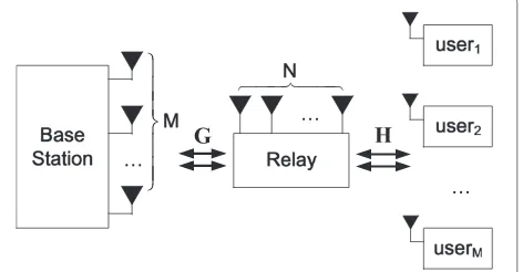
Consider a communication scenario including M users, one base station and one relay. As shown in Figure 1, the base station and the relay are both equipped with multiple antennas, whose antenna numbers areMandN, respec-tively, and each user is equipped with a single antenna. It is assumed that the number of relay antennas satisfies
N >Min order to meet the power constraint, as well as ensures that enough degrees of freedom can be provided. The half-duplexing constraint is applied to all nodes. All the channels are assumed to be quasi-statically indepen-dent and iindepen-dentically Rayleigh fading, and there is no direct link between the base station and the users. Both the base station and the relay have the access to the global CSI.
For such a scenario, the base station is required to trans-mit Mmessages to theMusers individually, while each user wants to send its own information to the base station
simultaneously. By jointly designing the precoding matri-ces at the base station and the relay, the messages from and to the same user can be aligned together, and trans-mitted to the users without co-channel interference, if the perfect CSI can be obtained. In the following part, we will introduce such a signal alignment scheme, which can accomplish the transmission between the base station and theMusers in two time slots.Unlike the ZF-SI scheme pro-posed by [10], the orthogonal projection is applied for relay precoding design in the proposed OP-SI scheme, which avoids severe relay noise amplification caused by the ZF-SI scheme and achieves significant performance gains.
During the first time slot, the base station and all the users transmit their messages to the relay simultaneously. To ensure that the matched messages from the base sta-tion and the users can be grouped together at the relay, the precoded messages are transmitted from the base station. Then the relay receives
r=GPs+Hx+nR, (1)
whereris theN×1 observation vector at the relay,Gis the
N×Mchannel matrix between the base station and the relay,His defined similarly for the relay and the users,nR is theN×1 additive Gaussian noise vector at the relay,s= [s1,. . .,sM]T andx=[x1,. . .,xM]T are theM×1 power normalized message vectors from the base station and the users, andxiandsiare denoted as the messages from and to theith user, respectively.
During the second time slot, the relay broadcasts the precoded observation to the base station and all the users. DenotingQas the precoding matrix at the relay, the relay transmissiontR= Qr. Then the observations at the base station can be given as
yB=GHQ(GPs+Hx+nR)+nB, (2)
and the observation at theith user can be given as
yi=hHi Q(GPs+Hx+nR)+ni. (3)
wherehHi is theN×1 channel vector between the relay and theith user,nBandniare the receive Gaussian noises at the base station and theith user, respectively.
The precoding design at the base station
The purpose of designing the precoding matrix P is to ensure that the relay can align the messages from and to the same user. To achieve such a target, the precoding matrix at the base station is defined as
P=αBGH(GGH)−1H. (4)
Note that a major part of this article focuses on the per-formance evaluation of the following proposed precoding
scheme, which is complicated and intractable. To simplify the derivation, the long-term power constraint is used in this article, which has been commonly used as shown in [15,16]. In this article, we assume that the transmission power at each antenna is constrained at 1, and therefore the total transmission power at the base station can be derived as
E{tr(PPH)} =αB2E{tr[HH((GGH)−1)HGGH(GGH)−1H]} =αB2E{tr[(GGH)−1(HHH)]}M. (5)
To obtain the simplified expression ofαB, the following lemma is introduced.
Lemma 1.Denoting thatA=GGH andB=HHH, we can derive
E{tr(A−1B)}2N−MMNK(N−M), (6)
where K = 2M−N−1(N(−NM)(+M2)() N−M+3), and the numbers of antennas must follow the constraint that N >M.
Proof.Please refer to the Appendix 1.
Applying the upper bound provided by Lemma 1, the power constraint factorαBcan be defined as
αB=
1
2N−MNK(N−M), (7)
which is a constant only related withM,N. According to the precoding matrix proposed by (4), the relay can obtain the aligned messages, which can be expressed as
r=H(αBs+x)+nR. (8)
The precoding design at the relay
As given by (1), the aligned messages for all the users are mixed together, which causes strong interference at the user side. To eliminate such interference, we introduce the relay precoding design in the following part. First, we can rewrite (1) as the mixture of the aligned messages for the users,
r= M
i=1
hi(αBsi+xi)+nR. (9)
can be generated by Gram-Schmidt process ofh1,. . .,hM, which can be presented as the determinant formula [17],
ui= nel matrix H by removing its ith column, i.e., Wi = [h1. . .hi−1hi+1. . .hM], andWjis defined similarly. Since
uican ensure thatuHi hj =0(i=j), the precoding matrix Qcan be generated as
Q=αRUUH, (11)
where αR is defined as the long-term relay power con-straint, andU =[u1,. . .,uM]. Apparently the precoding matrix can diagonalize channel matrix, which ensures that the interference at each user can be eliminated,
HHQH=α2Rdiag{|h1|2,. . .,|hM|2}. (12)
When the relay is with large number of antennas, the total transmission power at the relay can be approximated asa
To satisfy the transmit power constraint,αRcan be set as
Since the precoding matrices are both constructed, we can rewrite the observation at theith user as
yi=αR|hi|2(αBsi+xi)+αRhHi nR+ni, (15)
and the observation at the base station is
yB=αRGHUUHH(αBs+x)+αRGHUUHnR+nB. (16)
Performance analysis for the proposed OP-SI scheme
Due to the single antenna setting and the limited process-ing capability, the reception reliability at the user nodes becomes the bottleneck for the system transmissions. Therefore we will focus on the evaluation of the perfor-mance at the user node. Particularly both the ergodic sum
rate and the outage capacity for the OP-SI scheme are studied in this section.
Ergodic sum rate at the users with perfect CSI
Due to the observed signal given by (15), the SNR for the
ith user can be expressed as
SNROPi −SI= ρα 2
BαR2|hi|4 αR2|hHi ui|2+1
. (17)
To obtain the ergodic sum rate at the user, the joint PDF must be derived first, whose approximation is provided by the following lemma.
Lemma 2.Denoting x1= |hi|2and x2= |hHi ui|2, x1and x2are independent when the number of relay antennas N is large enough, and the joint PDF can be derived as
f(x1,x2)=f(x1)f(x2)=
Proof. The key idea is to prove that the two introduced Gaussian variableshiandhHi uiare independent when the number of relay antennas is large, which can ensure that their squared norms |hi|2 and|hHi ui|2are also indepen-dent. ApparentlyhiandhHi uiare joint normal distributed, since each linear combination of their components is nor-mally distributed [18]. Denotingz1 = hiandz2 = hHi ui, the joint PDF can be given as
f(z1,z2)= matrix, whose determinate is distributed as the product of
Mindependent chi-squared random variablesv1,. . .,vM,
When the number of relay antennasNtends to infinity, the degrees of freedom forvk also approach infinity for a fixedM. Due to the law of large numbers,vk becomes a constant, which can be given asvk =2(N+1−k). Then
expression for Wi can be obtained as well. For such a condition,uiin (10) can be further derived as
lim
Substituting the last equation into the covariance matrix , it becomes an identity matrix, which can ensure the independence ofhiandhHi ui[19], and so do their squared norms. It is well known that |hi|2 and |hHi ui|2 are chi-squared distributed and exponential distributed, respec-tively, then the joint PDF can be presented as
f(x1,x2)=f(x1)f(x2)=
And the proof is finished.
Based on the conclusion in Lemma 2, the following theorem about the ergodic sum rate at the users with perfect CSI can be presented.
Theorem 3.When the number of relay antennas N is large, the ergodic sum rate for the ith user with perfect CSI can be given as
CiOP−SI=1
Proof.Due to the SNR given by (17) and the joint PDF in Lemma 2, the ergodic sum rateCi can be derived as following,
The first term ofCiin the last equation can be further developed as
To achieve a closed-form expression for COPi −SI, an approximation for the large number of relay antennas is applied here. Note that the base station power constraint αB becomes large as N is large, and thus ραB2α2Rx21 +1 grows large as well. Then the last equation can be approx-imately expressed as [20]
E{log(αR2x2+ραB2α2Rx21+1)}
To further evaluate the performance of our proposed OP-SI scheme, a comparable scheme is selected, which is the ZF-SI scheme introduced by [10]. And the analysis result is presented by the following corollary.
Corollary 4.The proposed OP-SI scheme can achieve higher ergodic sum rate than the ZF-SI scheme, which is presented by [10], and the ergodic capacity gap of two schemes is provided as following when the SNR is high,
=CiOP−SI−CiZF−SI= 1
where CiZF−SI is denoted as the ergodic sum rate for the ZF-SI scheme.
Proof. To achieve the comparison results, we first derive the ergodic capacity for the ZF-SI scheme. Compared to OP-SI scheme, the same precoding is applied at the base station, while the ZF beamforming is utilized at the relay, which can be given as V = βRH(HHH)−1(HHH)−1HH whenN >M. And then the SNR for ZF-SI scheme at the
ith user can be derived as
SNRZFi −SI = ρβ station and the relay, respectively. To simplify the deriva-tion, the long-term power constraint is also used for the ZF-SI scheme, and the average power at the relay can be presented as an inverse Wishart matrix [21]. ThenβRcan be given as
βR=
For high SNR region, the ergodic sum rate for the ZF-SI signal alignment scheme can be derived as
CZFi −SI=E
Moreover, the ergodic sum rate of OP-SI can be approximated as
Then the gap between the ergodic capacities of two introduced schemes can be expressed as
=COPi −SI−CiZF−SI= 1
Corollary 4 shows clearly that our proposed scheme can achieve higher ergodic sum rate than the ZF-based scheme in [10]. According to the protocol description, the key idea of relay precoding design in this article is quite similar to the block diagonalization (BD) scheme, where the co-channel interference can be eliminated by using the null space of channel matrix. For the addressed sce-nario, the BD-based precoding schemes can outperform the ZF-based scheme, and such a phenomenon has been previously reported in [23].
Ergodic sum rate at the users with channel estimation error
Based on the perfect CSI assumption, the ergodic sum rate for the OP-SI scheme has been introduced in the previous part, where the interference can be eliminated completely. However, restricted by the imperfect feed-back or signal processing, it is hard for the users to get the perfect CSI. Typically channel estimation error can be modeled as follows. Particularly the perfect CSIhican be expressed as the sum of channel estimateshˆi and the estimation errorei,
hi= ˆhi+ei, H= ˆH+E, (36)
where Hˆ =[hˆ1,. . .,hMˆ ] and E =[e1,. . .,eM]. As dis-cussed in [12-14], hiˆ and eiˆ are independent, whose entries are complex Gaussian distributed with the vari-ance σe2 and (1 − σe2), respectively. When the channel estimation is imperfect, the interference at the users can-not be removed, since the precoding matrices are derived based on channel estimates. Then the observation at the relay can be expressed as
r=αBHsˆ +(Hˆ+E)x+nR= ˆH(αBs+x)+Ex+nR. (37)
And the observation at the base station is
yB=αRGHUˆUˆHHˆ(αBs+x)+αRGHUˆUˆHEx
+αRGHUˆUˆHnR+nB, (38)
and the observation at theith user can be given as
yi=αR|ˆhi|2(αBsi+xi)+αBαReHi UˆUˆHHsˆ
Then the signal to interference plus noise ratio (SINR) for theith user can be expressed as
SINROPi −SI= α the imperfect reception of s and x, respectively, n˜i =
1 ρ(αR2| ˆhi
Hˆ
UUˆH|2+σe2| ˆUUˆH|2+1)is the total noise at the
ith user. Then we can have the following theorem about the ergodic sum rate of the OP-SI protocol.
Theorem 5.When the number of base station antennas M is large, the ergodic capacity with channel estimation error can be approximately expressed as
rate COPi −SI for the ith user with imperfect CSI can be
The proof has been finished.
By using CiOP−SI introduced in the above theorem, we can analyze the impact of channel estimation error on the ergodic sum rate. When the channel estimation is free of error, both intra-stream and inter-stream interference can be perfectly avoided, andCOPi −SIequals to the ergodic sum rate with perfect CSI. When the channel estimation error exists with a fixed varianceσe2, we can derive the following equation with the high SNR assumption,
lim
The last equation shows thatCiOP-SItrends to a constant as SNRρ increases, which means that the gap between the ergodic sum rate with and without channel estima-tion error grows infinitely. Therefore, the system capacity is severely limited by the existence of channel estima-tion error, and it is necessary to improve the channel estimation accuracy.
Outage capacity at the users for OP-SI
To further evaluate the robustness of proposed OP-SI scheme, the analysis of outage capacity for each user is necessary. In this section, the outage capacities with and without channel estimation error are both studied. First, the definition of outage capacity can be presented as follows,
Definition 1.Outage capacity is the maximum trans-mission rate with a specified outage probability, which can be defined as
Cout=max
R {R|Pout(R) <pth}, (45)
where R is the transmission data rate, ptaris the threshold
for outage probability, and Pout(R)is the outage probability that can be defined as follows
Pout(R)=Pr{C<R}, (46)
where C is the capacity.
According to the definition of outage capacity, the out-age probability should be derived at first. Since the pro-posed OP-SI scheme aims to remove the co-channel inter-ference at the users, the outage probability for each user is considered independently in this article, and then we can provide the following theorem about outage probability with perfect CSI.
Theorem 6.The closed form expression of outage prob-ability for the ith user can be expressed as
Piout(Rtari )=e
where Rtari is the target transmission data rate for the ith user.
By setting Rtari = Cout−i and Pouti (Rtari ) = pi, which is
a specified value of outage probability, the outage capacity for the ith user with perfect CSI can be presented as
Cout−i=(Pouti )−1(pi), (48)
where (Piout)−1(·) is the inverse function of the outage probability Piout(R).
Proof. When the perfect CSI is available, the SNR for the
ith user is provided by (17) in the article. Due to the defi-nition of outage probability presented by (46), the outage probability for theith user can be developed as
whereRtari is the target transmission data rate for theith user,x1andx2follows the notation in the previous section of the article. By substituting the joint PDF ofx1andx2 into (49),Piout(Rtar)can be further derived as can be ensured for the last equation. Since the expres-sion ofPiout(Rtari )is so complicated that the closed-form expression ofCout−iis not easily tractable. In fact, outage capacity is still intractable even in a more simple scenario, such as in. Therefore, we can only obtain the symbolic expression ofCout−i. Particularly by settingRtari =Cout−i, the outage capacity for theith user can be expressed as follows for a given outage probabilitypi,
Cout−i=(Pouti )−1(pi). (51)
And the proof has been finished.
Then we focus on the outage capacity for the user with channel estimation error. Similar to the analysis above, the closed-form expression of outage probability needs to be derived at first, and then the outage capacity equals to the target data rate with fixed outage probability. And the analysis results are presented in the following theorem.
Theorem 7.When the channel estimation error exists, the outage probabilityPouti (Rtari )can be presented as
Pi 4)αR2σe2ρand all the other notations follows the previous subsection.
By setting Ritar = Cout−i andPouti (Rtari ) = pi, which is
a specified value of outage probability, the outage capacity for the ith user with perfect CSI can be presented as
Cout−i=(Pouti )−1(pi), (53)
where (Piout)−1(·) is the inverse function of the outage probability Piout(R).
Proof.Similar to the proof of Theorem 6, the outage probabilityPouti (Rtari )is first derived. By using the SINRi
where all the notations follow the previous subsection. As described in the proof of Theorem 5,xˆ1 and xˆ2 are two independent random variables that follow exponen-tial and Chi-squared distributions, respectively. Then the derivation ofPouti (Rtari )can be given as follows,
Then the outage capacityCout−ican be derived by deriv-ing the inverse function ofPouti (Cout−i)with a fixed outage probabilitypi, which can be expressed as
Cout−i=(Pouti )−1(pi). (56)
And the theorem has been proved.
The enhanced precoding design for the OP-SI scheme at the relay
0 5 10 15 20 25 30 0
5 10 15 20 25 30 35 40
Transmit power per antenna (dBm)
Total transmit power(dBm)
With long−term power constraints in (7) and (14) With instant power constraints
Total transmit
power at the base station Total transmit
power at the relay
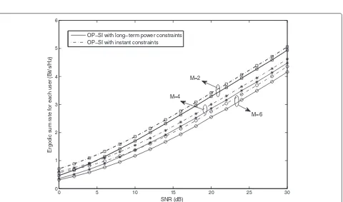
Figure 2Total transmit power at the base station and the relay for OP-SI with different power constraints.In Figure 2, the total transmit power at the base station and the relay are plotted. Particularly the numbers of antennas at the relay and the base station are set asN=3 and
M=2, respectively, and the power of noise is fixed as−10 dBm. As shown in the figure, the differences of between the schemes using the long term and instantaneous power constraints are quite small.
0 5 10 15 20 25 30
0 1 2 3 4 5 6
SNR (dB)
Ergodic sum rate for each user (Bit/s/Hz)
OP−SI with long−term power constraints OP−SI with instant constraints
M=2
M=4
M=6
process. In fact, there exists other available vectors forQ whenN > M. To further improve the performance gain, an enhanced OP-SI (eOP-SI) scheme is described in this section, where the relay follows an improved precoding generation with optimal precoding selection.
To eliminate the interference at the users, the relay pre-coding matrix can be designed as follows. Based on a submatrix ofH, an orthogonal projection matrixU†i can be generated for the aligned message ofsiandxi,
U†i =(IN−Wi(WHi Wi)−1WHi )N×N, i∈1,. . .,M. (57)
Due to the definition of the orthogonal projection matrix, the null space dimension forU†i is(M−1). There-fore, the dimension of the signal space equals to (N − M+1), and the fact thatU†ihk = hkHU†i = 0(i = k) can be easily observed [6]. ThusU†i is qualified to group the messages from and to theith user together without interference, andMprecoding matrices are needed. It will put a heavy burden on the relay. To derive a simplified
precoding matrix at the relay,U†i can be further decom-posed as
U†i =[u†i,1,. . .,u†i,(N−M+1)] [u†i,1,. . .,u†i,(N−M+1)]H, (58)
where u†i,1,. . .,ui†,(N−M+1) are the normalized basis vec-tors of the non-null space. The decomposition follows from the fact that the eigenvalues ofU†i are either 1 or 0. Recalling the fact thathHkU†ihk =0(i=k), we can derive that
hHkU†ihk=hHk[u
†
i,1,. . .,u †
i,(N−M+1)] ×[u†i,1,. . .,u†i,(N−M+1)]Hhk
= N−M+1
j=1
|hHku†i,j|2=0, i=k.
(59)
Therefore, each column vector of U†i can remove the interference. Assuming a qualified vector u†i has been selected, the precoding matrixQcan be generated as
Q=αRU†(U†)H, (60)
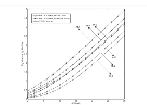
0 5 10 15 20 25 30
0 0.5 1 1.5 2 2.5 3 3.5 4 4.5 5
SNR (dB)
Ergodic capacity (bit/s/Hz)
OP−SI scheme, Monte Carlo OP−SI scheme, numerical results ZF−SI scheme
M=6
M=6 M=4
M=2
M=2
M=4
where αR is defined as the relay power constraint, and U† =[u†1,. . .,u†M]. Apparently the precoding matrix can diagonalize channel matrix, which ensures that the inter-ference at each user can be eliminated.
Due to the SNR given by (17), the transmission perfor-mance of theith user is decided by the chosen precoding vectoru†i. To improve the transmission performance, an appropriate precoding matrixQoptshould be generated, and the optimal precoding vector for each user can be selected according to the following rule,
uopti = arg u†k∈i
max SNRi,k|k=1,. . .,N−M+1 ,
(61)
where i = {u†i,1,. . .,u †
i,(N−M+1)}is the set of available precoding vectors for theith user, and SNRi,kis denote as the SNR achieved by theith user whenu†kis applied.
Furthermore, the power is allocated equally for each antenna in OP-SI. To further improve the transmission performance, the power optimization can be utilized at
the relay. Since the ergodic sum rate is studied in this article, the object of power allocation can be set as max-imizing the transmit sum rate, and the global optimal solution can be achieved by water filling [24].
When the channel estimation error exists, which is unpredictable, the exact SINR cannot be provided for the relay node. A feasible solution is to select the relay pre-coding matrix according to the estimated SNR, which can also improve the transmission performance as shown in the following section.
Numerical results
In this section, the performance of proposed OP-SI scheme is evaluated based on Monte Carlo simulations. In Figure 2, the total transmit power at the base station and the relay are plotted. And the transmit power are defined as
PB=αB2tr !
(GGH)−1(HHH)",
PR=αR2tr
(α2B+1)QHHHQH + 1
ρQQ
H
. (62)
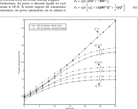
0 5 10 15 20 25 30
0 0.5 1 1.5 2 2.5 3 3.5 4 4.5 5
SNR (dB)
Ergodic capacity (bit/s/Hz)
OP−SI scheme, Monte Carlo
OP−SI scheme, numerical results σ e 2 =0
σe2 =0.01
σe2 =0.05
σe 2
=0.1
The comparable scheme is based on the instantaneous power constraint. Particularly the numbers of antennas at the relay and the base station are set asN = 3 and
M = 2, respectively, and the power of noise is fixed as −10 dBm. As shown in the figure, the transmit power with the long-term power constraint is very close to that with instant power constraint, which implies that the used bound is quite tight. Similarly, the difference of relay trans-mit power between the schemes using the long term and instantaneous power constraints is also quite small.
The ergodic sum rate of OP-SI with different power constraint schemes are also plotted by Monte Carlo simu-lation in Figure 3. As shown in the figure, the ergodic sum rate curves of OP-SI with two types of power constraints are very close in high SNR region, and the performance gap is less than 0.2 Bit/s/Hz. Therefore, although the ergodic sum rate is derived by using the long-term power constraints in this article, it also provides some insights for the performance of the scheme with the instant power constraint.
Figure 4 shows the ergodic sum rate of each user with perfect CSI, and the numbers of user and relay antennas
are set asM = 2, 4, 6 andN = M+1, respectively. To show the performance gains clearly, the ZF-SI scheme is selected as a comparable scheme. As shown in the figure, the capacity of each user decreases as the number of users increases, and the OP-SI scheme always achieves higher capacity than the ZF-SI scheme. Such a result ver-ifies the analysis results given by Corollary 4. Moreover, the numerical results based on Theorem 3 is provided as well, and the simulation results confirm that our derived closed-form expression for the ergodic sum rate perfectly matches the Monte Carlo results, specifically in the high SNR region.
In Figure 5, the parameter of the number of users is fixed as M = 2, and the number of relay antennas is
N = 3, while the differentσe2, which is the variance of channel estimation error, are set. When the OP-SI scheme is free of channel estimation error, the ergodic sum rate increases linearly as the SNR raises. Note that the ceiling of ergodic sum rate appears when the CSI is not per-fect, and the slopes of the curves for the ergodic sum rate are saturated faster with the increasing ofσe2, which means that the system capacity is seriously effected by the
0 5 10 15 20 25 30
0 1 2 3 4 5 6
SNR (dB)
Ergodic capacity (bit/s/Hz)
eOP−SI scheme,σ
e 2=0
OP−SI scheme,σ
e 2=0
eOP−SI scheme,σe2=0.01
OP−SI scheme,σe2=0.01
eOP−SI scheme,σe2=0.05
OP−SI scheme,σe2=0.05
channel estimation error. In addition, the approximation presented by Theorem 5 is also shown. The numeri-cal results demonstrate that our provided approximation is quite closed to the curves plotted by Monte Carlo simulation.
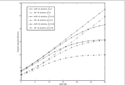
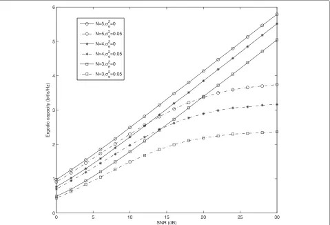
Figures 6 and 7 provide the performance evaluation for the eOP-SI scheme proposed in the previous section, and the number of users is set asM = 2. Figure 6 presents the ergodic sum rate of the eOP-SI scheme with and with-out channel estimation error. Compared with OP-SI, the eOP-SI scheme can always achieve higher ergodic capac-ity, whenever the perfect CSI is available. The capacity gap between the two schemes enlarges as the SNR increases at first, and then tends to stable in the high SNR region. In Figure 7, the ergodic sum rate with different relay anten-nas numbers is presented, where we fix the number of relay antennas asN = 3, 4, 5, respectively. As shown in the figure, the ergodic sum rate of eOP-SI scheme raises with the increment of the relay antennas. Based on the simulation results, the optimal relay precoding selection of eOP-SI scheme achieves higher ergodic sum rate than the fixed relay precoding design of OP-SI scheme, and
such performance gain grows larger as the number of relay antennas increases.
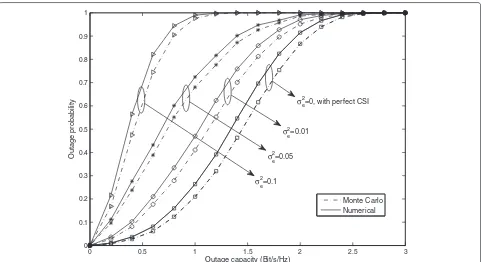
Figure 8 provides the relationship between outage prob-ability and outage capacity. Particularly the numbers of antennas at the base station and the relay are set asM=2 and N = 3, respectively, and the SNR is fixed asρ = 15 dB. As shown in the figure, the outage capacity can be improved by increasing the outage probability. And the outage performance becomes worse when the variance of channel estimation errorσe2increases. The simulation results also show that the derived analysis results are quite close to the Monte Carlo simulation.
Conclusion
In this article, an OP-SI scheme is proposed for the MIMO relaying channels, where the base station exchanges mes-sages with multiple users via the help of a relay. When the perfect global CSI is provided, the desired messages can be aligned at the relay by carefully constructing pre-coding at the base station and relay, and the co-channel interference can be removed completely. The derived closed-form expression demonstrates that our proposed
0 5 10 15 20 25 30
0 1 2 3 4 5 6
SNR (dB)
Ergodic capacity (bit/s/Hz)
N=5,σe2=0
N=5,σ
e 2=0.05
N=4,σ
e 2=0
N=4,σ
e 2=0.05
N=3,σe2=0
N=3,σe2=0.05
0 0.5 1 1.5 2 2.5 3
=0, with perfect CSI
Figure 8Outage probability vs. outage capacity for OP-SI.Figure 8 provides the relationship between outage probability and outage capacity, whereM=2 andN=3, and the SNR is fixed asρ=15 dB. As shown in the figure, the outage capacity can be improved by increasing the outage probability. And the outage performance becomes worse whenσe2increases. The simulation results also show that the derived analysis results are quite close to the Monte Carlo simulation.
OP-SI scheme can achieve higher ergodic sum rate than the existing ZF-SI scheme. To evaluate the effort of chan-nel estimation error, the ergodic sum rate with imperfect CSI is also investigated. Both the analytical and numerical results indicate that the system performance is seriously decreased with the increment of the covariance of channel estimation error. To improve the transmission perfor-mance, an eOP-SI scheme is also introduced, which can further improve the transmission performance by using precoding selection at the relay.
Appendix 1
Proof of Lemma 1
It can be easily verified thatAandBare two independent Wishart matrices, and thusA−1andBare positive semi-definite matrices, whose trace is positive. Due to the Von Neumann’s trace inequality [25], it can be derived that
E{tr(A−1B)}E
whereλiandωiare the eigenvalues for the matricesAand B, respectively,λ1· · ·λM,ωM · · ·ω1, andλmin is the minimal eigenvalue ofA. And the joint probability
density function (PDF) for the ordered eigenvalues ofA can be given as following,
where the last equation follows the fact thatλ1,. . .,λM−1 can be treated as the ordered eigenvalues of a Wishart matrix generated by a(M−1)×(N+1)Gaussian matrix, and thus the integrand of the second integral in (66) can be expressed asf(λ1,. . .,λM−1)/KM−1,N+1. From (65),K
Then the expectation of 1/λmincan be bounded as
E
it is important to point out that the integral of λN−M−1exp−12λtends to infinity whenN=M. There-fore, to obtain the upper bound of 1/λmin in (68), the constraint of antennas numbers thatN > Mshould be followed. It is easy to know that tr(B) is Chi-square dis-tributed, and tr(B)∼ 12χ2(2MN). Then we can derive that
E{tr(B)} =MN, andE{tr(A−1B)}can be bounded as
E{tr(A−1B)}2N−MMNK(N−M). (69)
And the lemma is proved.
Endnotes
aDue to the proof of Lemma 2 in the following section,u
i approaches to 0 asNincreases, anduHi uj(i=j)also tends to 0. And thusUUH is approximately treated as an iden-tity matrix.
bThe approximation follows the inequality that| ˆUUˆH|2 | ˆU|2| ˆUH|2 = M2, and an upper bound ofn˜i is derived here. In fact, it is quite close to n˜i, and the following derivation of SINROP-SIi cannot ensure this inequality. Thus it is treated as an approximation.
Competing interests
The authors declare that they have no competing interests. Acknowledgements
This study was supported in part by National Natural Science Foundations of China (Grant Nos. 61222103 and 61072058), the State Major Science and Technology Special Projects (Grant Nos. 2010ZX03003-003-01 and 2010ZX03005-002-02), the Postgraduate Innovation Fund of SICE-BUPT 2011,BUPT Excellent Ph.D. Students Foundation (Grant No. CX201211) the Fok
Ying Tong Education Foundation Application Research Projects (Grant No. 122005), the Program for New Century Excellent Talents in University, the U.K. Engineering and Physical Sciences Research Council under Grant
EP/I037423/1, and FP7 Marie Currie International Outgoing Fellowship. Author details
1Wireless Signal and Network Lab, Key Laboratory of Universal Wireless Communications, Ministry of Education, Beijing University of Posts and Telecommunications, Beijing, China.2School of Electrical, Electronic, and Computer Engineering Newcastle University, Newcastle, NE1 7RU, UK.
Received: 18 March 2012 Accepted: 11 September 2012 Published: 3 October 2012
References
1. JN Laneman, DNC Tse, GW Wornell, Cooperative diversity in wireless networks: efficient protocols and outage behavior. IEEE Trans. Inf. Theory.50(12), 3062–3080 (2004)
2. R Ahlswede, N Cai, S-YR Li, RW Yeung, Network information flow. IEEE Trans. Inf. Theory.46(4), 1204–1216 (2000)
3. S Zhang, S Liew, P Lam. Physical layer network coding., inThe 12nd Annual International Conference on Mobile Computing and Networking, (Los Angeles, 2006) pp. 358–365
4. S Katti, S Gollakota, D Katabi. Embracing wireless interference: analog network coding., inACM SIGCOMM, (Kyoto, 2007) pp. 397–408 5. M Peng, C Yang, Z Zhao, W Wang, H Chen, Cooperative network coding
in relay-based IMT-advanced systems. IEEE Commun. Mag.50(4), 76–84 (2012)
6. Z Zhao, Z Ding, M Peng, W Wang, KK Leung, A special case of multi-way relay channel: when beamforming is not applicable. IEEE Trans. Wirel. Commun.10(7), 2046–2051 (2011)
7. M Peng, H Liu, W Wang, H-H Chen, Cooperative network coding with MIMO transmission in wireless decode-and-forward relay networks. IEEE Trans. Veh. Technol.59(7), 3577–3588 (2010)
8. R Zhang, Y-C Liang, CC Chai, S Cui, Optimal beamforming for two-way multi-antenna relay channel with analogue network coding. IEEE J. Sel. Areas Commun.27(5), 699–712 (2009)
9. N Lee, J-B Lim, J Chun, Degrees of freedom of the MIMO Y channel: signal space alignment for network coding. IEEE Trans. Inf. Theory.56(7), 3332–3342 (2010)
10. Z Ding, I Krikidis, J Thompson, KK Leung, Physical layer network coding and precoding for the two-way relay channel in cellular systems. IEEE Trans. Signal Process.59(2), 696–712 (2011)
11. GJ Foschini, MJ Gan, On limits of wireless communications in a fading environment when using multiple antennas. Wirel. Persl. Commun.6(3), 311–335 (1998)
12. M Medard, The effect upon channel capacity in wireless communications of perfect and imperfect knowledge of the channel. IEEE Trans. Inf. Theory.46(3), 933–946 (2000)
13. T Yoo, A Goldsmith, Capacity and power allocation for fading MIMO channels with channel estimation error. IEEE Trans. Inf. Theory.52(5), 2203–2214 (2006)
14. J Wang, S Jin, Z Liu, Y Wang, X Yu. WLC06-3: analysis of the sum capacity of MIMO broadcast systems with channel estimation errors., inIEEE 49th Global Telecommunications Conference, (San Francesco, 2006) pp. 1–5 15. D Chen, JN Laneman, Modulation and demodulation for cooperative
diversity in wireless systems. IEEE Trans. Wirel. Commun.5(7), 1785–1794 (2006)
16. Y Zhu, P Kam, Y Xin. Non-coherent for amplify-and-foward relay systems in a Rayleigh fading environment., inIEEE 50th Global Telecommunications Conference, (Washington, 2007), pp. 1658–1662
17. W Greub,Linear Algebra.4th edn. (Springer, New York, 1975)
18. A Gut,An Intermediate Course in Probability.2nd edn. (Springer, New York, 2009)
19. E Melnick, A Tenenbein, Misspecifications of the normal distribution. Am. Stat.36(4), 372–373 (1982)
20. IS Gradshteyn, IM Ryzhik,Table of Integrals, Series, and Products.6th edn. (Academic Press, Amsterdam, 2000)
21. AM Tulino, S Verdu,Random Matrix Theory and Wireless Communications
22. JT Kent, KV Mardia, JM Bibby,Multivariate Analysis(Academic Press, Amsterdam, 1979)
23. QH Spencer, A Lee Swindlehurst, M Haardt, Zero-forcing methods for downlink spatial multiplexing in multiuser MIMO channels. IEEE Trans. Signal Process.52(2), 461–471 (2004)
24. A Paulraj, R Nabar, D Gore,Introduction to Space-Time Wireless Communications(Cambridge Univ. Press, Cambridge, 2003) 25. L Mirsky, A trace inequality of John Von Neumann. Monatshefte fur
Mathematik.79(4), 303–306 (1975)
doi:10.1186/1687-1499-2012-308
Cite this article as:Zhaoet al.:On the user performance of orthogonal projection signal alignment scheme in MIMO relay systems.EURASIP Journal on Wireless Communications and Networking20122012:308.
Submit your manuscript to a
journal and benefi t from:
7Convenient online submission
7Rigorous peer review
7Immediate publication on acceptance
7Open access: articles freely available online
7High visibility within the fi eld
7Retaining the copyright to your article