CSEIT161217 | Received: 17 October 2016 | Accepted: 25 October 2016 | September-October-2016 [(2)5: 115-119]
International Journal of Scientific Research in Computer Science, Engineering and Information Technology © 2016IJSRCSEIT | Volume 1 | Issue 2 | ISSN : 2456-3307
115
Automatic Generation Control of Multi-Area Power System-A
ANN Approach
Santosh Kumar Suman, Vinod Kumar Giri
Department of electrical engineering, Madan Mohan Malaviya University of Technology, Gorakhpur, India
ABSTRACT
This paper, fundamental controller system is presented for Automatic Generation Control of three-area interconnected power system. The objective of providing an Automatic Generation Control (AGC) has been to maintain the system frequency at nominal value and the power interchange between different areas at their programmed values. The main requirement of an interconnected AGC is to ensure that frequency of various bus voltages and currents are maintained at near specified nominal values, tie-line power flowing among the interconnected areas are maintained at specified levels, and total power requirement on the system as a whole is shared by individual generators economically in optimum fashion. The simulations have been performed using MATLAB.
Keywords : Automatic Generation Control (AGC), Load Frequency Control (LFC), Tie-line ANN Controller, Area Control error (ACE).
I.
INTRODUCTION
Noble excellence of electrical power system means both the voltage and frequency to be fixed at desired values irrespective of change in loads that occurs randomly. It is in fact impossible to maintain both active and reactive power without control which would result in variation of voltage and frequency levels. To cancel the effect of load variation and to keep frequency and voltage level constant a control system is required. Though the active and reactive powers have a combined effect on the frequency and voltage, the control problem of the frequency and voltage can be separated. [1]
Frequency is mostly dependent on the active power and voltage is mostly dependent on the reactive power. Thus the issue of controlling power systems can be separated into two independent problems. The active power and frequency control is called as load frequency control (LFC).[2] The most important task of LFC is to maintain the frequency constant against the varying active power loads, which is also referred as un- known external disturbance. Power exchange
error is an important task of LFC. Generally a power system is composed of several generating units. To improve the fault tolerance of the whole power system, these generating units are connected through tie-lines. This use of tie-line power creates a new error in the control problem, which is the tie-line power exchange error. When sudden change in active power load occurs to an area, the area will get its energy through tie-lines from other areas.[3]
If the load on the system is suddenly increased, then the speed of the turbine drops before the governor could adjust the input of the steam to this new load. As the change in the value of speed decreases the error signal becomes lesser and the position of the governor and not of the fly balls gets nearer to the point required to keep the speed constant. One way to regain the speed or frequency to its actual value is to add an integrator on its way. The integrator will monitor the average error over a certain period of time and will overcome the offset Thus as the load in the system changes continuously the generation is adjusted automatically to restore the frequency to its nominal value. This method is known as automatic generation control (AGC). [5]
II.
METHODS AND MATERIAL
1. Scientific Modeling
According to practical point of view, the load frequency control problem of interconnected power system is much more important than the isolated (single area) power systems. Whereas the theory and knowledge of a isolated power system is equally important for understanding the overall view of interconnected power system.
Generally now days all power systems are tied with their neighboring areas and the Load Frequency Control Problem become a joint undertaking. Some basic operating principle of an interconnected power system is written below:
1. The loads should strive to be carried by their own control areas under normal operating conditions, except the scheduled portion of the loads of other members, as mutually agreed upon.
2. Each area must have to agree upon adopting, regulating, control strategies and equipment which are beneficial for both normal and abnormal conditions.
2. Dynamics of the Power System
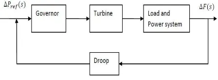
The AFLC circle is primarily connected with the vast size generators .The fundamental point of the main aim of the automatic load frequency control (ALFC) can be to keep up the sought unvarying recurrence, in order to gap loads among generators despite dealing with the trading of tie line control in agreement to the booked
frequency control loop are as given a technique shown in the Fig.1 [5]
Figure 1. Block diagram of automatic frequency control
3. Governors
Governors are employed in power systems for sensing the bias in frequency which is the result of the modification in load and eliminate it by changing the turbine inputs such as the characteristic for speed regulation (R) and the governor time constant (Tg). Mathematically
( ) ( ) (1)
Where ( ) Ggovernor output
( ) The reference signal R=Regulation constant or droop
( ) Frequency deviation due to speed
4. Turbine
Turbines are used in power systems for the conversion of the natural energy, like the energy obtained from the steam or water, into mechanical power (Pm) which can be conveniently Supplied to the generator .There are three categories of turbines usually used in power systems: non-reheat, reheat in addition to hydraulic turbines, each and every one of which may be modeled and designed by transfer functions. In the model the representation of the turbine is,
( )
( ) (2)
Where ( ) The input to the turbine
( ) The output from the turbine
5. Generators
power transformation. The speed of the rotor is proportional to the frequency of the power system. The loads of the power can be divided into resistive loads (PL), which may be fixed when there is a change in the rotor speed due to the motor loads which change with the speed of the load. If the mechanical power does not change then the motor loads shall compensate the change in the load at a rotor speed which is completely dissimilar from the planned value
Mathematically
( )
( ) (6)
Where ( ) the output from the generator
( ) The input to the generator
Time constant to the generator
6. Load
The power systems load constitutes of a diversity of electrical devices. The loads that are resistive, for example lighting and also heating loads are not dependent on frequency, but the motor loads are responsive to frequency depending on the speed-load characteristics as shown below
(7)
Where Non frequency responsive load change
Frequency responsive load change D=% Change in load/% change in frequency
7. Tie-lines system
The objective of tie-lines is to trade power with the systems or areas in the neighborhood whose costs for operation create such transactions cost-effective. Moreover, even though no power is being transmitted through the tie-lines to the neighborhood systems/areas and it so happens that suddenly there is a loss of a generating unit in one of the systems. During such type of situations all the units in the interconnection experience a alteration in frequency and because of which the desired frequency is regained.
Let there be two control areas and power is to be exchanged from area 1 to area 2.
Mathematically
| || |
( )
(8)
Where 1stand for control area 1&2 stand for area 2
Series reactance involving area 1 and 2
| | and | |=Magnitude of voltage of area 1 plus area 2
8. Control Error
The aim of LFC is not just to terminate frequency error in all areas, but as well to enable the exchange of the power due to tie-line as scheduled. In view of the fact that the error due to tie-line power will be the integral of the dissimilarity in frequency among every pair of areas, but when we direct frequency error back to zero, all steady state errors present in the system frequency will give rise to in tie-line power errors. For this reason it is necessary to consider the control input in the variation in the tie-line power. Consequently, an area control error (ACE) is stated. Each of the power generating area considers ACE signal to be used as the output of the plant. By making the ACEs zero in all areas makes all the frequency along with errors in the tie line power in the system as zero.
In order to take care of the total interchange of power among its areas within the neighborhood, ALFC utilizes real power flow determinations of all tie lines as emanating through the area and there after subtracts the predetermined interchange to compute an error value. The total power exchange, jointly with a gain, B (MW/0.1Hz), known as the bias in frequency, as a multiplier with the divergence in frequency is known as the Area Control Error is specified by
ACE=∑ ( )MW (9)
Where
Power in the tie line(if out of the area then positive)
Planned power exchange Based frequency
Positive ACE shows that the flow is out of area.
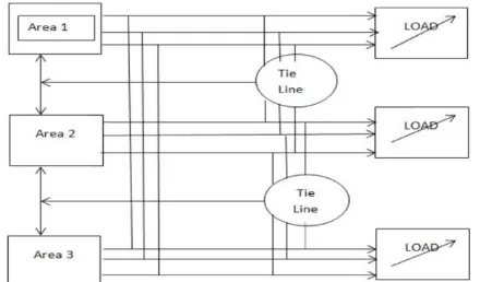
9. Three Area Power System
Figure 2. block diagram of three area power system
In this case of three area power system an assumption is taken that the individual areas are strong and the tie line which connects the two area is weak. Here a single frequency is characterized throughout a single area; means the network area is „strong‟ or „rigid‟. There may be any numbers of control areas in an interconnected power system.
III.
RESULTS AND DISCUSSION
Integral Controller Approach
The integral control composed of a frequency sensor and an integrator. The frequency sensor measures the frequency error Δf and this error signal is fed into the integrator the input to the integrator is called the Area Control Error (ACE). The ACE is the change in area frequency, which when used in an integral-control loop, forces the s steady-state frequency error to zero.
The integrator produces a real-power command signal ΔPc and is given by
- ∫ (10)
= ∫( )
Input of speed change
Integral gain constant
Simulation Result
Figure 5. Frequency deviation vs time in area 2
Figure 6. Frequency deviation vs time in area 3
IV.CONCLUSION
In this paper, analysis is done on the simulation study, for load disturbance in all three areas with integral controller gives very less frequency deviation approx. to zero. the ANN controller is very effective in suppressing the frequency oscillations caused by rapid load disturbances and it will improve the system performance (voltage regulation) by effectively reduce the overshoot. The results are shown that by using the time delay the dynamic response of the system will increase and the degradation in the system performance can be compensated effectively using ANN controller .
V.
REFERENCES
[1] Abhijit Chakrabarti, and Sunitha Halder, “Power System Analysis Operation and Control”, Prentice-Hall of India, New Delhi, PP: 537-573, 2008
[2] A.K Mahalanabis, D.P Kothari, and Ahson, S.I.: „Computer aided power system analysis and control‟, Tata McGraw–Hill, 1988.
[4] Fosha C.E., Elgerd O.I., The megawatt – frequency control theory, IEEE Trans. Power Appl. Syst. (1970) Vol.89, pp. 563 – 571
[5] P. M. Anderson, A. A. Fouad, and H. H. Happ, \Power system control and stability, "Systems, Man and Cybernetics, IEEE Transactions on, vol. 9, no. 2, p. 103, Feb. 1979.
[6] J. Lee, “On methods for improving performance of PI-type fuzzy logic controllers”, IEEE Trans. On Fuzzy Systems, Vol. 1, No. 4, pp. 298, Nov. 1993.
[7] G. A. Chown and R. C. Hartman, “Design and experience with a Fuzzy Logic Controller for Automatic Generation Control (AGC)”, IEEE Trans. Power Syst., Vol. 13, No. 3, pp. 965-970, Nov. 1998.
[8] W. C. Chan and Y. Y. Hsu, “Automatic Generation of Interconnected Power Systems using Variable Structure Controllers”, IEE Proc., pt. C, Vol. 128, No. 5, Sept.1981, pp. 269-279. [9] Zeynelgil, H. L., Demiroren, A. and Sengor, N.
S. “The application of ANN technique for automatic generation control for multi-area power system.”, Journal of Electric power and Energy systems, Vol. 24, pp. 345-354, 2002. [10] Kirchmayer Leon, K., “Economic operation of
Power systems”, Wiley India Pvt. Ltd., IIIrd Edition, 2009.
[11] A. Kumar, O. P. Malik and G. S. Hope, “Variable Structure System Control Applied to AGC of an Inter-Connected Power System”, IEEE Proc., Gener. Transm. Distrib., Vol. 132, No. 1, 1985, pp. 23-29.
[12] J.R. Jang, “ANFIS: Adaptive-network-Based Fuzzy Inference System”, IEEE Trans. On Systems, Man and Cybernetics, Vol. 23, No.3, pp. 665- 685, May. 1993.
[13] Gayadhar Panda, Sidhartha Panda and C. Ardil, “Hybrid Neuro Fuzzy Approach for Automatic Generation Control of Two–Area Interconnected Power System”, International Journal of Computational Intelligence, Vol. 5, No. 1, pp. Pradesh (Affiliated to Utter Pradesh Technical University), Lucknow India with B.Tech degree in Electrical Engineering in 2013.Resently; He is pursuing M.Tech (Control & Instrumentation) in Electrical Engineering Department of Madan Mohan Malaviya University of Technology (Formerly Madan Mohan Malaviya Engineering College), Gorakhpur (UP). Published five research papers in International Referred Journals and two research papers in IEEE Conferences. His research interests‟ area includes Intelligent Techniques, Optimization Technique, Control System, Signal Processin, Measurement and Instrumentation, ECG.