Volume 2011, Article ID 496763,13pages doi:10.1155/2011/496763
Research Article
MU-MIMO in LTE Systems
Jonathan Duplicy,
1Biljana Badic,
2Rajarajan Balraj,
2Rizwan Ghaffar,
3P´eter Horv´ath,
4Florian Kaltenberger,
3Raymond Knopp,
3Istv´an Z. Kov´acs,
5Hung T. Nguyen,
6Deepaknath Tandur,
1and Guillaume Vivier
71Agilent Technologies Laboratories, Wingepark 51, 3110 Rotselaar, Belgium
2Intel Mobile Communications (IMC), D¨usseldorfer Landstraße 401, 47259 Duisburg, Germany 3Eurecom, 2229 route des Crˆetes, B.P. 193, 06904 Sophia Antipolis Cedex, France
4Department of Broadband Infocommunications, Budapest University of Technology and Economics,
Goldmann Gy¨orgy t´er 3., 1111 Budapest, Hungary
5Nokia Siemens Networks Denmark A/S, Niels Jernes Vej 10, 9220 Aalborg, Denmark
6Department of Electronics Systems, Aalborg University, Niels Jernes Vej 12, 9220 Aalborg, Denmark 7Sequans Communications, Le Parvis de La D´efense 19, 92 073 Paris La D´efense Cedex, France
Correspondence should be addressed to Jonathan Duplicy,jonathan [email protected]
Received 1 December 2010; Revised 2 February 2011; Accepted 8 March 2011
Academic Editor: Rodrigo C. De Lamare
Copyright © 2011 Jonathan Duplicy et al. This is an open access article distributed under the Creative Commons Attribution License, which permits unrestricted use, distribution, and reproduction in any medium, provided the original work is properly cited.
A relatively recent idea of extending the benefits of MIMO systems to multiuser scenarios seems promising in the context of achieving high data rates envisioned for future cellular standards after 3G (3rd Generation). Although substantial research has been done on the theoretical front, recent focus is on making Multiuser Multiple-Input Multiple-Output (MUMIMO) practically realizable. This paper presents an overview of the different MU-MIMO schemes included/being studied in 3GPP standardization from LTE (long-term evolution) to LTE Advanced. MU-MIMO system concepts and implementation aspects have been studied here. Various low-complexity receiver architectures are investigated, and their performance assessed through link-level simulations. Appealing performance offered by low-complexity interference aware (IA) receivers is notably emphasized. Furthermore, system level simulations for LTE Release 8 are provided. Interestingly, it is shown that MU-MIMO only offers marginal performance gains with respect to single-user MIMO. This arises from the limited MU-MIMO features included in Release 8 and calls for improved schemes for the upcoming releases.
1. Introduction
Wireless data usage is increasing faster now than ever before. Smartphones and broadband-enabled portables, such as laptops or tablets, are now seeing high penetration in many
markets, and the superior user experience offered by such
devices has lead to exponential growth of mobile data traffic
as shown in [1]. The demand for mobile data services has
increased by an average of 160% in the year 2009 alone, and some mobile carriers have experienced even more aggressive growth numbers. According to a recent forecast, the global
mobile data traffic is expected to continue to double every
year through 2014, leading to a global compound annual
growth rate of 108% [2].
These large capacity demands can be met only by highly
efficient and optimized mobile network infrastructures.
Significant improvements are expected with the ongoing roll-out of OFDMA- (Orthogonal Frequency Division Multiple Access-) based networks: IEEE 802.16x (WiMAX) and 3GPP (3rd generation partnership project) LTE. These two standards, although they do not fulfill the requirements, are the first steps towards the 4th generation (4G) definition given by the International Telecommunications Union (ITU) and targeting data rates of 100 Mbps in high-mobility applications and 1 Gbps for low-mobility applications such as nomadic/local wireless access.
evolution and LTE Advanced). Among these various tech-niques, two promising ones are currently being investigated by EU FP7 project SAMURAI (Spectrum Aggregation and
Multiuser MIMO: ReAl-World Impact) [3], namely,
car-rier aggregation and MU-MIMO. The main objective of SAMURAI project is to investigate innovative techniques in the area of MU-MIMO and SA with focus on practical implementation and deployment aspects.
This paper aims at giving an insight into MU-MIMO schemes included/being studied in 3 GPP releases. MU-MIMO concepts, fundamentals, and an overview of already published research results and current outcomes from SAMURAI project are shown in this paper. Specifically, Section 2provides a detailed overview of the different MU-MIMO schemes from LTE Release 8 to Release 10 (known as LTE Advanced). In addition, a novel scheduling algorithm based on the geometrical alignment of interference at the
base station which minimizes the effective interference seen
by each user equipment (UE) is shown. InSection 3, receiver
design for MU-MIMO is addressed. The performance of both interference unaware and interference aware (IA) types of receiver algorithms has been studied in an LTE downlink
system. Performance/complexity tradeoff is summarized.
System level simulations are provided in Section 4, and
gains offered by MU-MIMO schemes with respect to
single-user MIMO (SU-MIMO) schemes in LTE Release 8 are
emphasized. Finally, conclusions are given inSection 5.
Regarding notations, we will use lowercase or uppercase letters for scalars, lowercase boldface letters for vectors, and
uppercase boldface letters for matrices. Furthermore,|·|and
· indicate the norm of scalar and vector while (·)T, (·)∗,
and (·)† stand for the transpose, conjugate, and conjugate
transpose, respectively.
2. Overview of MU-MIMO in 3GPP Standards
2.1. Theoretical Foundations of MU-MIMO. Spatial dimen-sion surfacing from the usage of multiple antennas promises
improved reliability, higher spectral efficiency, and spatial
separation of users. This spatial dimension is particularly beneficial for precoding in the downlink of MU cellular system, where spatial resources can be used to transmit data to multiple users simultaneously. The MIMO transmission techniques are integral parts of the LTE and WiMAX standards. A good overview of the MIMO techniques and configuration supported in these radio access technologies
can be found in [4–7].
In MU-MIMO mode, the transmissions to several termi-nals are overlapped in the same time-frequency resources by exploiting the spatial diversity of the propagation channel. In order to fully exploit MU-MIMO transmission modes, the spatial streams intended to the targeted terminals need to be well separated, ideally orthogonal at both transmit and receive sides. As a consequence, the theoretical performance gain of the MU-MIMO over SU-MIMO is expected to significantly increase in spatially correlated channels and with increasing number of transmit antenna at the enhanced Node B (eNB). Various linear and nonlinear precoding techniques and the corresponding receiver structures have
been proposed in the literature in order to achieve promising
MU-MIMO gains, see, for example, [8–12].
Optimal precoding in MU-MIMO Gaussian broadcast channel involves a theoretical preinterference subtraction
technique known as dirty paper coding (DPC) [10]
com-bined with an implicit user scheduling and power loading algorithm. Linear precoding techniques such as channel
inversion (CI) [11] and regularized channel inversion (RCI)
[12] cancel the interference in the former case while
attenuating it in the latter case. These precoding strategies strive to transform the cross-coupled channels into parallel noninteracting channels therefore transforming MU down-link into parallel SU systems. They are assuming Gaussianity of the interference. However, in the real world, inputs must be drawn from discrete constellations which have (non-Gaussian) structures that can be exploited in the detection process.
For practical purposes, the derived theoretical solutions have to be further adapted to the requirements and restric-tions of standardized air interfaces. The following secrestric-tions summarize some of the critical physical layer design aspects.
2.2. Overview of 3GPP LTE PHY MIMO
2.2.1. Reference Signals. The downlink transmission schemes are supported at physical layer by a set of downlink reference signals. These reference signals can be either UE specific or cell specific. The latter are referred to as common reference signals (CRSs) while the former are referred to as dedicated (or demodulation) reference signals (DRSs or DM-RSs). The CRSs are not precoded signals and are used by the UE for channel estimation, while the DM-RSs are precoded and used for demodulation purposes on the scheduled physical resource blocks (PRBs). The 3GPP standard defines the transmission of one time-frequency pattern for CRS and
DM-RS assigned to one real or virtualantenna port.
2.2.2. Transmission Modes. The defined SIMO (Singe-Input Multiple-Output) and MIMO transmission schemes are
categorized in severaltransmission modes. The definition of
each transmission mode includes the required configuration information in the common downlink signaling channel and information on how the user terminal should search for
this configuration message [13]. This mechanism is part of
the general downlink signaling framework designed to allow a flexible time-frequency resource allocation separately to each UE based on the available system resources and the reported or measured channel conditions. The transmission mode for each UE is configured semistatically via higher layer signaling, in order to avoid excessive downlink signaling.
2.2.3. Precoding. A major prerequisite for SU- and MU-MIMO transmission schemes is the use of precoding mecha-nisms at the transmit side. In 3GPP LTE/LTE Advanced, dif-ferent codebooks have been defined depending on the num-ber of transmit antenna ports, and they provide precoding support for simultaneous transmission of variable number
The precoding is applied to the data transmission to a target UE based on the channel feedback received from that UE, including a channel rank indicator (RI), channel quality indicator (CQI), and precoding matrix indicator (PMI). The RI indicates the estimated number of simultaneous layers which can be received by the UE. One or more layers can
be mapped to the samecodewordand are jointly encoded for
transmission to the same target UE. The RI is estimated at the UE as a wideband measure, that is, the same channel rank is assumed on all allocated resources. The CQI is an index in the modulation coding scheme (MCS) and transport block
size (TBS) index table (32 different entries). The PMI is
an index in the codebooks defined for a given number or transmit antenna ports (1, 2, 4 in LTE and up to 8 for LTE Advanced). The CQI information is always derived under the assumption that the selected PMI will be applied to the next scheduled transmission. A more detailed analysis of the LTE MU-MIMO precoding mechanisms and codebook use
is presented inSection 2.6.
2.2.4. Signalling and Terminal Feedback. The physical layer procedures defined for LTE Release 8 support various mechanisms of controlling the transmission parameters with
both higher-layer and lower-layer signaling [13, 14]. The
time-frequency granularity of the feedback to be sent by the UE is configured by the network via the downlink signaling channel and scheduling grants. Certain restrictions apply mainly due to requirement of minimizing the downlink and uplink signaling overheads. In practice, this means that each
of the definedtransmission modessupports a certain limited
set of physical layer transmission schemes and feedback schemes.
There are two main categories of CQI/PMI feedback mechanisms defined in the time domain: periodic and aperiodic. The RI is always a frequency nonselective type feedback and is associated with the corresponding CQI/PMI feedback. The supported time-frequency CQI/PMI feed-back granularities determine the overall feedfeed-back amount, and the supported configurations depend on the physical uplink channel utilized. The aperiodic feedback—frequency selective—is supported on the uplink shared channel and is available only when the UE has downlink/uplink transmis-sion scheduled while for the periodic feedback—frequency non/selective—both uplink control and shared channels can
be used [13].
2.3. LTE Release 8. The first release of LTE (Release 8) was aimed at defining the new OFDMA-based air-interface and introduced advanced single-user MIMO transmission
schemes, which were evaluated to be sufficient to meet
the set performance targets [4–7, 15]. Transmission from
up to four antenna ports is supported. The spatial multi-plexing or diversity MIMO transmission schemes, that is, in-cluding MU-MIMO, use only the nonprecoded CRS while the precoded DRS can support single-user single-layer beamforming schemes.
In LTE Release 8 there is only one transmission mode defined which allows, for MU-MIMO scheme to be used,
Table1: CQI and PMI feedback types for transmission mode 5 in LTE.
Feedback CQI type PMI type
Aperiodic
Higher-layer configured, set of subbands: subband and wideband CQI per codeword
Single PMI
Periodic
Wideband CQI for first codeword spatial differential CQI for RI>1
Single PMI
Periodic
UE-selected subbands: full CQI for first codeword spatial differential CQI for RI>1
Single PMI
thetransmission mode 5(TM5). When configured in TM5, the UE assumes that the eNB transmission on the downlink shared channel is performed with a single layer (stream). For the case of two transmit antenna ports, the standard specifies the use of four precoders based on two bits feedback from the UEs. In the case of four transmit antenna ports, the number
of precoders increases to sixteen, which can be found in [16].
The downlink control information (DCI) format used
for TM5 is format 1D, which includes a 1-bit power offset
information, indicating whether a 3 dB transmit power reduction should be assumed or not.
In terms of terminal feedback and CQI/PMI reporting modes, the LTE MU-MIMO TM5 can use both aperiodic
and periodic feedback types, see Table 1. When aperiodic
reporting is configured, then the wideband CQI and higher layer selected subband CQI in combination with a single PMI is supported. The full CQIs are reported for each codeword. When periodic reporting is configured then either wideband CQI or UE-selected subband CQI in combination with a single PMI is supported. The full CQI is reported
for the first codeword only, and differential CQI is used for
the second codeword when the reported RI>1. Single (or
wideband) PMI means that the reported PMI corresponds to and assumes transmission on all selected subbands reported for the CQI(s) and RI.
This is a rather minimal MU-MIMO transmission scheme and relies heavily on the accuracy of the RI/CQI/PMI feedback which was optimized for SU-MIMO transmission schemes. Inevitably, this limits the achievable MU-MIMO performance.
port and scrambling code allocations are wideband, so it is not always possible to ensure orthogonality even when only 2 users are multiplexed in MU-MIMO mode. Furthermore, the only fall-back transmission mode which is supported, without mode reconfiguration, is the transmit diversity. A fully adaptive SU/MU-MIMO transmission mode is not supported in LTE Release 9 but is expected to be introduced in Release 10 as described in the next section.
2.5. LTE Advanced. The specifications of LTE have been
extended for LTE Advanced [17]. At the time of writing, the
specifications had not been finalized, but several details are already in place. The final specifications are expected to be frozen in March 2011.
Configurations with up to 8×8 MIMO are to be
sup-ported, and new reference signals have been introduced to support both demodulation of the DM-RS and channel state information estimation (CSI-RS). Hence, special attention has been given to the signaling needed for more advanced SU/MU-MIMO schemes. A new transmission mode has been defined which now includes both SU and MU-MIMO transmission capabilities without the need for the UEs to be reconfigured via higher-layer signaling when switching between SU and MU transmission/reception on the shared
data channel [18]. This is thetransmission mode 9(TM9).
Consequently, the set of precoding codebooks has been
also extended for LTE Advanced [19]. For configuration with
2- and 4-transmit antenna, the LTE-Advanced codebook is the same as the corresponding LTE codebooks. For configurations with 8-transmit antenna, a dual-codebook approach is used. The precoding to be used in the dual-codebook approach is obtained via multiplication of two
precoding matricesW1andW2, whereW1is block diagonal
matrix matching the spatial covariance matrix of
dual-polarized antenna setup, and W2 is the antenna selection
and cophasing matrix. This configuration provides good performance in both high and low spatial correlation
channels. The W1 are obtained from the coefficients of a
Digital Fourier Transform (DFT) corresponding to different
transmission ranks, seeTable 2, with details in [19].
Backwards compatibility for Release 8 and 9 UEs has been targeted. This means that many of the LTE-Advanced features and associated signaling are not visible for the Release 8 and 9 UEs, and the transmission schemes defined for LTE are fully supported.
The UE feedback definition has been also extended in LTE Advanced to account for the dual-codebook structure. When operating in a cell with 8-transmit antenna config-uration, the LTE-Advanced UEs are required to include in the feedback information the PMI corresponding to both
W1 and W2. When only 2- or 4-transmit antenna are
configured/used at the eNB, the feedback includes only the
PMI for W2, and the W1 is the identity matrix.
Further-more, the aperiodic CQI/PMI reporting schemes defined for LTE have been extended to support the dual codebook
[20]. The PMI for W1 is always reported as a wideband
PMI corresponding to the entire system bandwidth. The aperiodic feedback modes include the configurations with
Table2: Codebook design in LTE Advanced for 8-transmit ante-nna.
Tx rank Beams W1 W2
Rank 1-2 32 16 (per rank) 16 (per rank)
Rank 3-4 16 4 (per rank) 16 (rank 3), 8 (rank 4)
Rank 5–7 1 4 1 (per rank)
Rank 8 1 1 1 (per rank)
wideband CQI-subband PMI W2, wideband + “Best-M”
CQI-wideband + “Best-M” PMI W2, and subband
CQI-wideband PMIW2.
At this stage, not all LTE-Advanced MIMO specifications have been finalized, and there are still several open aspects to be addressed. Proposals to improve the CQI/PMI feedback also for 2- and 4-transmit antenna configurations, targeting both MU-MIMO and SU-MIMO improvement, are yet to be considered. Similar to the LTE Release 8 and 9 design principles, these further improvements have to take the
performance versus signaling overhead tradeoffinto account
even when utilizing the new transmission mode introduced in LTE Advanced. The natural extensions of the RI/CQI/PMI feedback periodic and aperiodic reporting schemes already defined in LTE are to be further investigated in this context.
2.6. Optimal Precoding Strategy for LTE Release 8. The LTE Release 8 precoders are of low resolution and are further based on the principle of equal gain transmission (EGT). As these precoders have been designed for SU-MIMO
transmission, their efficient employment for MU-MIMO
mode (TM5) is not yet fully understood. This has led to the common perception that MU-MIMO is not workable in LTE
[21, page 244]. In this section, we investigate the effectiveness
of these low-resolution precoders for MU-MIMO mode in LTE and consider a geometric scheduling algorithm which outperforms SU-MIMO and transmit diversity schemes. This algorithm is based on the geometrical alignment of
interference at eNB which minimizes the effective
interfer-ence seen by each UE.
2.6.1. System Model. We restrict ourselves to the case of dual-antenna eNB and single-dual-antenna UEs. The system equation
for LTE TM5 at thek-th resource element (RE) is given as
y1,k=h†1,kp1,kx1,k+h†1,kp2,kx2,k+z1,k, (1)
wherey1,kis the received symbol at UE-1, andz1,kis the zero
mean circularly symmetric complex white Gaussian noise of
varianceN0.x1,kandx2,kare the complex symbols for
UE-1 and UE-2, respectively. h†1,k = [h∗11,k h∗21,k] symbolizes
the MISO channel from eNB to UE-1 at thek-th RE. Since
the processing at UE is assumed to be performed on an RE basis for each received OFDM symbol, the dependency on RE index can be ignored for notational convenience.
each UE would feedback the precoder which maximizes its received signal strength. Therefore, in accordance with the low-resolution LTE precoders, the UEs compute quantized versions of their respective matched filter (MF) precoders,
that is, the UE first measures its channelh†1 = [h∗11 h∗21]
from eNB and consequently computes the MF precoder, that
is, [h11 h21]T(the normalized version involves a division by
h1). As LTE precoders are characterized by unit coefficients
as their first entry, the UE normalizes first coefficient of the
MF precoder, that is,
pMF= h
Second coefficient indicates the phase between two channel
coefficients. Now based on the minimum distance between
pMFand LTE precoders, one of the four precoders is selected
by the UE, and the index of that precoder is fed back to the
eNB. Let that precoder bep1 =[1q]T,q ∈ {±1,±j}. From
the geometrical perspective, this precoder once employed by
the eNB would alignh∗21withh∗11in the complex plane so as
to maximize the received signal power, that is,|h∗11+qh∗21|2
subject to the constraint that the precoder allows rotation of
h∗
21by 0◦,±90◦, or 180◦. Therefore, this precoding ensures
that h∗11 and h∗21 lie in the same quadrant as shown in
Figure 1(b), thus maximizing the received SNR.
2.6.3. Scheduling. In LTE MU-MIMO mode (TM5), dual antenna eNB can serve two UEs on the same time-frequency resources. We assume a densely populated cell where eNB has the requested precoders of most of the UEs in the cell. Here, we consider a scheduling algorithm for MU-MIMO mode where eNB selects the second UE in each group of allocatable
RBs whose requested precoderp2is 180◦ out of phase from
the precoderp1of the first UE to be served on the same RBs,
that is, the precoder matrix is given asP=1/√41 1q−q . So
the received signal by UE-1 is given as
y1=
where selection of the precoder for each UE would ensure
maximization of its desired signal strength, that is,|h†1p1|
2
for the first UE and|h†2p2|
2
for the second UE while selection of the UE pairs with out-of-phase precoders would ensure minimization of the interference strength seen by each UE,
that is,|h†1p2|
2
for the first UE and|h†2p1|
2
for the second UE. Note that these maximization and minimization are subject to the constraint of the utilization of low-resolution LTE precoders. This scheduling strategy would ensure that the UEs selected to be served in MU-MIMO mode on the same time-frequency resources have good channel separation.
Though this precoding and scheduling strategy would ensure minimization of the interference, the residual inter-ference would still be significant due to the low resolution of LTE precoders. The employment of single-user receivers
by the UEs (thereby assuming Gaussianity of
interfer-ence) would be highly suboptimal. In Section 3.2, we will
deliberate on a low-complexity IA receiver which exploits interference structure in the detection of desired stream.
2.6.4. Extension to Four Transmit Antennas. In the case of 4 available transmit antennas, the algorithm described above
can be straightforwardly extended. The main difference is
in the scheduling, where we pair two users with the highest chordal distance of their respective precoders.
3. Receiver Design and Link-Level Studies
This section highlights performance of various receivers for MU-MIMO transmission in LTE systems. Main chal-lenges for an MU-MIMO receiver implementation include fast channel estimation and equalization, reliable multi-user interference cancelation, and complexity issues. The detection method implemented plays a significant role in the resulting performance of MU-MIMO systems, and the main problem leading to the notion of infeasibility of MU-MIMO mode in LTE is the receiver structure employed by the UE being unaware of the interference created by the signal for the other UE. Although the scheduling algorithm discussed in Section 2.6 minimizes the interference based on the geometrical alignment of the channels and the precoders, the residual interference is still significant. Gaussian assumption of this significant interference and the subsequent employ-ment of conventional single-user detectors in this scenario would be highly suboptimal thereby leading to significant degradation in the performance.
3.1. Receiver Overview. Maximum likelihood (ML) detection is optimal but exponentially complex as the number of antennas or the size of transmission alphabet increases. In descending order of complexity, a number of suboptimal methods range from the successive interference cancelation (SIC) to the simple linear detectors. Nonlinear algorithms,
such as decision feedback-based [22] or tree-based detectors
[23], perform near the optimum, but still at the expense of a
high complexity. Linear detectors, for example, zero-forcing (ZF) or minimum mean square error (MMSE) criteria, are considerably less complex than ML, but these detectors can
suffer a significant performance loss in fading channels in
particular in correlated channels [24]. This class of linear
detectors also includes the interference rejection combiner
(IRC) studied in [25] as a special case. These algorithms are
as such readily applicable to LTE systems.
3.2. Low-Complexity Interference-Aware Receiver. Another approach for robust LTE DL detection is the low-complexity
IA receiver proposed in [26]. This receiver exploits the
h∗
11
h∗
11
h∗
11 h∗11
h∗
21
h∗
21
qh∗
21
−qh∗
21
UE
(a) (b) (c)
eNB
Figure1: (a) shows the original channel from eNB to UE, while (b) shows the effective channel of desired signal and (c) shows the effective channel of interference of UE.
or MMSE filters. This low-complexity receiver being based on the MF outputs and devoid of any division operation is
suitable for implementation in the existing hardware [27].
A performance comparison of the IA receiver with a
standard (interferenceunaware) receiver for TM5 is given in
Figure 2. For comparison, we also consider fallback trans-mit diversity (TM2) and closed-loop SU-MIMO schemes (TM6). We consider ideal OFDM system (no intersymbol interference (ISI)) and analyze the system in the frequency
domain where the channel hasiidcomplex Gaussian matrix
entries with unit variance and is independently generated for each channel use. We assume no power control in MU-MIMO mode, so two UEs have equal power distribution. It is assumed that the UE knows its own channel from the eNB,
so in MU-MIMO mode, UE can find the effective channel of
interference based on the fact that the eNB schedules second
UE on the same RE which has requested 180◦out-of-phase
precoder. Note that the MCS for a particular user is the same in each set of simulations. So where one UE is served with a particular MCS in TM6 or TM2, two UEs are served with the same MCS in MU-MIMO (TM5) mode thereby doubling the
sum spectral efficiency.
However, the prerequisites of this IA receiver are the knowledge of interference channel and its constellation.
Though the scheduling strategy described in Section 2.6
enables the UE to find the effective interference channel
(product of interference precoder and own channel), the information regarding the interfering constellation is still eluded due to the DCI formats in LTE do not allow the trans-mission of this information to the UE. The question is how much sensitive this IA receiver structure is to the knowledge of interfering constellation? To this end, we propose a blind IA receiver in the Appendix which is aware of the interference channel but is unaware of the interfering constellation.
InFigure 3, we look at the sensitivity of the IA detector to the knowledge of the constellation of interference for MU-MIMO mode in LTE. The simulation settings are the same except that we additionally consider the case when UE has no knowledge of the constellation of interference and
thus employs the blind receiver which assumes the unknown interference to be from 16QAM. For comparison purposes, we also consider the cases once UE assumes the unknown interference to be from QPSK and 64QAM. The results show that there is negligible degradation in the performance of the system once the blind IA receiver is employed by the UE which assumes interference to be from 16QAM. This behavior is attributed to the fact the postulation of
16QAM not only captures the effect of four quadrants of
QPSK constellation points but also encapsulates the spread of 64QAM constellation points in each quadrant thereby leading to a reasonable compromise.
3.3. Performance and Complexity Study. The performance and complexity study is split into two parts. First, we give
a brief performance comparison of different receiver
archi-tectures in the case of dual antenna eNBs and dual antenna
UEs. Secondly, we look at the IA detector [26] in more detail
and in the case of dual-antenna eNBs and single-antenna UEs. In both cases, we assume optimal scheduling of users
according toSection 2.6.
In this study, we compare IRC studied in [25], the IA
detector from [26], and a low-complexity, single-user, linear
MMSE (LMMSE) detector. The effect of feedback delay,
channel estimation, and spatial correlation has been con-sidered in the investigation. The downlink MU-MIMO LTE
Release 8 system investigated is described inSection 2.3. For
the link-level evaluation, the parameters defined inTable 3
have been assumed. Due to the straightforward implemen-tation, Least-Squares (LS) channel estimation technique has been applied in investigation.
The results are shown in Figures 4–6. Block error rate
(BLER) is presented as a function of the average SNR in dB. For comparison, LTE TM4, SU-MIMO with the ratio of PDSCH (Physical Downlink Shared Channel) EPRE (Energy
Per Resource Element) to cell-specific RS EPRE of−3 dB is
shown as a reference scenario.
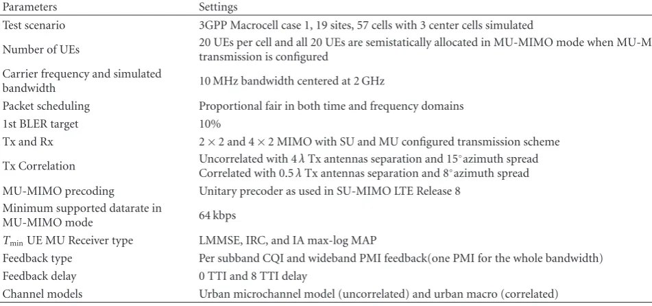
Table3: Basic LTE Parameters Used in the Simulations.
Parameters Settings
Test scenario 3GPP Macrocell case 1, 19 sites, 57 cells with 3 center cells simulated
Number of UEs 20 UEs per cell and all 20 UEs are semistatically allocated in MU-MIMO mode when MU-MIMOtransmission is configured
Carrier frequency and simulated
bandwidth 10 MHz bandwidth centered at 2 GHz
Packet scheduling Proportional fair in both time and frequency domains
1st BLER target 10%
Tx and Rx 2×2 and 4×2 MIMO with SU and MU configured transmission scheme
Tx Correlation Uncorrelated with 4λTx antennas separation and 15◦azimuth spread Correlated with 0.5λTx antennas separation and 8◦azimuth spread
MU-MIMO precoding Unitary precoder as used in SU-MIMO LTE Release 8
Minimum supported datarate in
MU-MIMO mode 64 kbps
TminUE MU Receiver type LMMSE, IRC, and IA max-log MAP
Feedback type Per subband CQI and wideband PMI feedback(one PMI for the whole bandwidth)
Feedback delay 0 TTI and 8 TTI delay
Channel models Urban microchannel model (uncorrelated) and urban macro (correlated)
uncorrelated channels. The performance of the LMMSE detector degrades with increasing modulation order. For QPSK, IRC slightly outperforms IA max-log MAP (Maxi-mum A Posteriori) detector. However, for 64QAM IA
signif-icantly outperforms IRC by almost 5 dB at 10−2BLER. This
can be explained by the fact that IA detector exploits not only the interference structure but also performs joint detection as it is aware of the modulation from the interfering user.
The joint effect of feedback delay and channel correlation
is illustrated for 16QAM and IA detectors in Figures5and
6. In uncorrelated channels (Figure 5), the feedback delay
results in up to 2 dB loss at 10−2BLER. However, in the case
of high channel correlation, the corresponding performance
is reduced by up to 5 dB at 10−2BLER for feedback delay of 8
TTIs (transmit time interval) as shown inFigure 6.
The results shown here demonstrate the possible gains of IA receivers and indicate that the IA type of receivers are good candidates for the practical implementation in MU-MIMO LTE systems. It has been shown that one can obtain the best overall performance with the IA max-log MAP detector if the modulation of the paired UEs is known. However, additional control information bits dedicated to this modulation update may not be desirable as they will increase the downlink overhead and not comparable with the current standardization. By doing a smart scheduling, it is possible to indicate what type of modulation is used for the paired UEs without having dedicated overhead bits for this purpose. The UEs are always informed which MCS will be applied to the next transmitted data packet. In the pairing and selection process, we can then select or force the secondary UEs to have the same modulation as the primary one. To see how often we can actually perform the scheduling of the UE pair having the same modulation, the statistic of the scheduled MU-MIMO UEs pair with their corresponding
MCSs is presented inSection 4.2.
4. System Level Performance
4.1. Channel Modeling. Due to its key role in system performance, the propagation channel needs to be accurately modeled. Proper correlation modeling is critical for MU-MIMO performance assessment. The most advanced models proposed so far are geometry-based stochastic channel
mod-els (GSCM), like the WINNER II model [28]. These models
explicitly model the geometry of the scenario by choosing random scatterer locations according to some prespecified
distribution and might incorporate large-scale fading effects
into the channel realizations. When considering a complex scenario, the models inherently take antenna patterns, relative transmitter-receiver locations, angles, and so forth into account. Hence, the correlation matrices become truly UE dependent and time varying which is in accordance with measurement results. In addition, the WINNER II might account for a distance-dependent correlation between
the large-scale fading parameters experienced by different
terminals situated in the same geographical area.
4.2. Spatial MU-Packet Scheduler (MU-PS) in LTE Release 8. The packet scheduler for SU-MIMO transmission is often carried out in two phases: time domain packet scheduler (TDPS) and frequency domain packet scheduler (FDPS). An overview of this TD-FD PS framework in downlink LTE
system can be found, for example, in [29,30]. When
MU-MIMO transmission scheme is configured, the UE can be scheduled in SU-MIMO (Rank 1) mode or MU-MIMO mode depending on whether the set multi-user UE pairing condition(s) is (are) met or not. For the pairing purpose, the UEs are classified into primary UEs and candidate UEs
[8]. To comply as much as possible with the SU-MIMO
2 3 4 5 6 7 8 9 10−3
10−2
10−1
100
SNR
BLER
LTE TM6
LTE TM5-IA receiver
LTE TM2
LTE TM5-SU receiver 16QAM
(a)
9 10−3
10−2
10−1
100
SNR
BLER
6 7 8 10 11
LTE TM6
LTE TM5-IA receiver
LTE TM2
LTE TM5-SU receiver 64QAM
(b)
Figure2: BLER versus SNR (dB) comparison of a single-user (SU) receiver and the IA receiver in TM5. The performance of TM6 and TM2 is also shown for comparison. 3GPP LTE rate 1/3 turbo code (punctured to rare 1/2) with 16QAM (a) and 64QAM (b) modulation is used. Both eNb and UE have two antennas, and the channel is i.i.d. Rayleigh fading.
0 2 4 6 8 10 12 14 16
10−4
10−3
10−2
10−1
100
SNR
BLER
of
x1
Interference actual
Interference assumed to be QPSK
QPSK-QPSK 64QAM-64QAM
16QAM-16QAM
Interference assumed to be 16QAM Interference assumed to be 64QAM
Figure3: BLER versus SNR (dB) of the blind IA for three different constellation orders (e.g., QPSK-QPSK indicates that bothx1and
x2 are QPSK). “Interference actual” implies the case once UE knows
the constellation of interference (x2).
MU-candidate UEs are all UEs with the first transmission (1st Tx). This means UEs with retransmission (2nd Tx) will not be selected as the candidate UEs. This restriction is made in order to facilitate the implementation of Hybrid automatic repeat request (HARQ) procedures where certain number of
RBs should be reserved for the retransmissions [29]. By not
allowing the 2nd Tx UEs to be candidate UEs, we can make sure that they will be allocated the resource and scheduled as in the SU-MIMO configuration. For each PRB, from the list of MU-candidate UEs, we try to find the best UE to pair
−10 −5 0 5 10 15 20 25 30
SNR (dB)
BLER
10−3
10−2
10−1
100
QPSK 1/3
64QAM 3/4
16QAM 1/3
Figure 4: BLER versus SNR [dB] performance of MU-MIMO receivers for various modulation orders, urban micro (uncorre-lated), 30 km/h, no feedback delay, LS-channel estimation. Line legend: black solid: TM4, SU-MIMO, red: IRC, blue: max-log MAP, green◦: LMMSE.
with the primary UE. The criterion for selection is that the candidate UE should have an assigned precoder orthogonal to that of the primary UEs. This condition is applied to make sure that the UEs would not cause too much multi-user interference (MUI) to each other. To avoid scheduling the UEs at the cell edge into MU-MIMO mode, the predicted throughput of both the primary UE and the candidate UEs at
the considered PRB should be larger than a thresholdTmin.
metrics in MU mode larger than that of the primary in SU mode. Normally, we have a list of candidate UEs that meet these requirements. From this list, the candidate UE that has the highest PF metric in MU mode will be finally paired with the primary UEs and set to MU transmission mode. If none of the candidate UEs meet the first three requirements, the primary UE will transmit in SU mode as normal.
According to LTE Release 8 specification, the UEs are assumed to be semistatically allocated into MU-MIMO
mode. In the MU-MIMO mode (Mode 5 [13]), the current
control signaling of MU-MIMO parameters is the DCI format 1D. With this 1D DCI format, the UEs assume that an eNB transmission on the PDSCH would be performed
on one layer [13]. There is one additional bit to indicate the
power sharing/offset and therefore imply the transmission
mode of the UEs, for example, SU-MIMO mode or MU-MIMO mode. Due to this specification, the UE scheduled in the SU-MIMO will not use the rank adaptation and only be transmitted in the single-stream mode.
4.3. Performance of LTE Release 8 MU-MIMO. Early
eval-uations for the LTE 2×2 MU-MIMO schemes employing
various practical precoding approaches (unitary or ZF) and receiver types have disclosed gains over SU-MIMO of up to
20% only in scenarios with high transmit correlation [8]. The
precoder granularity was shown to have impact mostly in low-medium transmit correlation scenarios. These conclu-sions were later confirmed by more extensive investigations,
in, for example, [4,6,7].
To give an idea on the performance of LTE Release 8 MU-MIMO system, here we provide the system level
results of 2×2 and 4×2 MU-MIMO configurations. The
performance of corresponding SU-MIMO systems is also illustrated as a baseline. To comply with the Release 8 specification, the CQI/PMI feedback scheme with per-subband CQI and wideband PMI as reported from the UEs
was selected [13]. To make a fair comparison, this feedback
scheme was applied for both the SU-MIMO and MU-MIMO transmission configurations. The major input parameters for
the simulations are shown inTable 3.
Figure 7illustrates the distribution of the user
through-put for 4×2 MIMO with SU and MU transmission
con-figuration. The same trend is observed for the 2×2 MIMO
setting, and therefore the distribution of the user throughput for this case is not shown. The cell average throughputs for
2×2 and 4×2 MIMO systems with SU and MU
transmis-sion configuration are illustrated inFigure 8. It is observed
that with a higher Tx correlation the performance of both SU-MIMO and MU-MIMO is better as compared with the low Tx correlation scenario. This behavior can be explained by the use of wideband PMI. In the uncorrelated Tx antennas scenario, using wideband PMI is not optimum as the fading channel varies quite a lot within the transmission bandwidth used. This leads to a degradation in the performance. On the contrary, when the Tx antennas are correlated, a single wideband PMI represents the optimal precoder for the whole transmission bandwidth. In this case, using either wideband PMI or subband PMI will not change the performance picture.
BLER
10−3
10−2
10−1
100
0 2 4 6 8 10 12 14 16 18 20 22
TM4, SU-MIMO (0 TTIs) TM4, SU-MIMO (8 TTIs)
IRC (0 TTIs)
IRC (8 TTIs) MMSE (0 TTIs) MMSE (8 TTIs) SNR (dB)
2 dB loss
Max-log MAP (0 TTIs)
Max-log MAP (8 TTIs)
Figure 5: BLER versus SNR (dB) performance of MU-MIMO receivers for 16QAM modulation, urban micro, 30 km/h, LS-channel estimation, and feedback delay.
0 2 4 6 8 10 12 14 16 18 20 22
SNR (dB)
BLER
10−3
10−2
10−1
100
TM4, SU-MIMO (0 TTIs) TM4, SU-MIMO (8 TTIs) IRC (0 TTIs)
IRC (8 TTIs)
Up to 5 dB loss with feedback delay
Max-log MAP (0 TTIs)
Max-log MAP (8 TTIs)
Figure 6: BLER versus SNR (dB) performance of MU-MIMO receivers for 16QAM modulation, urban macro, 30 km/h, LS-channel estimation, and feedback delay.
From the cumulative distribution function of the user throughput, it is observed that the 95% ile (peak) user throughput of the MU-MIMO system is lower than that of the SU-MIMO system. At the 5% ile (cell edge) user
throughput there is no difference in the performance of
MU-MIMO system and SU-MIMO system. This behavior comes from the fact that in the MU-MIMO PS we try not
0 0.5 1 1.5 2 2.5
4×2 SU-MIMO uncorrelated
4×2 MU-MIMO uncorrelated
4×2 MU-MIMO uncorrelated no MUI
4×2 SU-MIMO correlated
4×2 MU-MIMO correlated
4×2 SU-MIMO correlated no MUI
Figure7: Distribution of the user throughput and the average cell throughput for 4×2 MIMO setting.
For both 2×2 MIMO and 4×2 MIMO settings and
in both uncorrelated and correlated Tx antennas scenarios, with full multi-user interference, the MU-MIMO system performs worse than the SU-MIMO system with respect to the average cell throughput. Changing the Tx antenna correlation condition, from uncorrelated to correlated, there is an improvement in the average cell throughput of MU-MIMO system, but the enhancement is marginal. The loss in
the average cell throughput for 2×2 MU-MIMO system and
4×2 MU-MIMO system as compared with the
correspond-ing SU-MIMO system is−7% and−6%, respectively.
For Release 8 UE, it is possible to implement a blind
receiver structure as proposed in the Appendix. Figure 3
shows that our proposed blind receiver can work well for all combinations of the modulation order of the MU-MIMO
UE pairs except the 64QAM-QPSK combination. InFigure 9,
we show the statistics of the scheduled MU-MIMO UEs pair with their corresponding modulation order. It can be seen that up to 40% of the scheduled MU-MIMO pairs have the same modulation order (2-2) QPSK-QPSK, (4-4) 16QAM-16QAM, and (6-6) 64QAM-64QAM. In max 20% of the cases, the modulation order of the paired MU UEs is (6-2,2-6) 64QAM-QPSK. Therefore, we can safely avoid scheduling UE pairs that have this combination of modulation order.
Based on these observations, we further assume a perfect interference canceling algorithm as upper bound for the practical performance of the blind receiver structure as
proposed in the Appendix. Figures7and8show the system
level results obtained under these receiver assumptions. In uncorrelated Tx scenario, even with perfect multi-user inter-ference cancelation, the performance of MU-MIMO system
is inferior to that of the SU-MIMO system. This indicates that one should not use MU-MIMO in an uncorrelated
Tx scenario. In a correlated Tx scenario, 2×2 MU-MIMO
system and 4×2 MU-MIMO system obtain a gain in the
average cell throughput of 3% and 11%, respectively. The CQI/PMI feedback scheme used for the results
presented in Figures7and8was limited to the specifications
of LTE Release 8. More features are now investigated and pro-posed in LTE-Advanced standardization, which can facilitate the optimal MU-MIMO transmission and reception. The next section explores some of the potential improvements to be introduced.
4.4. LTE-Advanced Enhancements
4.4.1. Specific CQI and PMI. Using the SU-MIMO codebook for MU-MIMO transmission may not fully utilize the multi-user diversity. This is because the SU-MIMO codebook is designed to optimize the performance of a single user, while the additional degree of freedom in the spatial domain one can obtain in the MU-MIMO transmission is not fully taken into consideration. Therefore, it could be beneficial if there is a separated codebook designed specifically for MU-MIMO transmission mode. The multigranular precoder is expected to boost the performance of MU-MIMO system
performance as described in [31–33]. Of course, this could
raise concern on the increased feedback overhead since an additional MU-MIMO precoder needs to be feedback in parallel with the normal SU-MIMO precoder. Another proposed solution is to report the CQI/PMI separately
for SU-MIMO and MU-MIMO transmissions [34,35]. In
addition to the normal SU CQI/PMI feedback, UE capable of receiving MU-MIMO reception could report an additional best companion UE PMI and the expected CQI with that
setting. To reduce the feedback overhead, only the difference
(delta) between the MU-CQI and SU-CQI is fed back as extra information. These schemes allow for a dynamic switching between SU and MU modes. One of the drawbacks of these types of proposals is that more feedback overhead is introduced. Moreover, if the paired UEs are restricted to have the same precoding as the best companion precoding, then the number of potential UEs available for pairing at the eNB will be very limited. This could significantly reduce the number of UEs scheduled in MU-MIMO mode and thereby prohibit cell level of the performance gain from using MU-MIMO transmission.
4.4.2. Link Adaptation and Scheduling. Although the outer
loop link adaptation [36,37] can help to adjust the estimated
SU MU SU MU Figure8: The average cell throughputs for 2×2 MIMO and 4×2 MIMO settings.
2-2 (2-4, 4-2) (2-6, 6-2) (4-4) (4-6, 6-4) (6-6)
2×2 MU-MIMO uncorrelated
2×2 MU-MIMO correlated
4×2 MU-MIMO uncorrelated
4×2 MU-MIMO correlated
Figure9: Distribution of the combination of the modulation order observed at scheduled MU UEs.
of accuracy. Currently, the most common way of estimating the MU-MIMO CQI is to estimate it from the
single-stream SU-MIMO CQI reported by the UE with some offset.
Particularly for 2×2 MU-MIMO, the offset is around 4.7 dB
to account for the power sharing of the two UEs scheduled
on the same PRB and the MU interference. The offset value
should be differently set for different transmission schemes,
for example, orthogonal unitary precoder or ZF. This is because the unitary precoder is already normalized, so that
it has norm one. The difference between the SU-MIMO and
MU-MIMO comes mainly from the transmission power to the UE in each mode and the MU interference. Meanwhile for ZF, the mismatch between the estimates of MU-MIMO CQI also comes from the fact that the precoder used in the estimation of the SU-MIMO CQI at the UE side is totally
different from the actually used transmit ZF precoder at the
eNB side.
With the introduction of the DM-RS in LTE Advanced, as the multi-user precoded signals can be estimated at the UE, it is possible to implement a better performing LMMSE receiver with a better multi-user interference covariance matrix estimation.
MU-MIMO scheduling is very much dependent on how much information on the channel can be feedback by the
UEs to the serving eNB. There is therefore tradeoff in
the performance improvement and the feedback overhead. Currently, in LTE Release 8, the UEs are semistatically allocated to MU-MIMO mode. It means that the UE can not switch from MU-MIMO transmission configuration to
SU-MIMO (Rank>1) transmission configuration between
subframes. As mentioned inSection 4.2, together with the
specified DCI format, these rules limit the UE comparability in using rank adaptation when it is not scheduled in MU-MIMO mode. This issue is expected to be solved in LTE Advanced when an additional transmission mode (Mode 9) and new DCI format are introduced. This mode would allow for a dynamic switching between SU-MIMO and MU-MIMO and support an SU-MIMO up to rank 8
[18].
5. Conclusions
This paper provides a detailed overview of the MU-MIMO schemes encountered in 3GPP standardization, from a unique mode in LTE Release 8 to more advanced possibilities
offered by LTE Advanced. Moreover, a new scheduling
algorithm based on the geometrical alignment of interference at the base station is proposed. This algorithm minimizes the
effective interference seen by each UE.
Various receiver structures are studied. Their
perfor-mance is assessed in different scenarios at link level. The
noted that these issues have been addressed in SAMURAI, and the outcomes will be published at a later date.
System level simulations for LTE Release 8 are presented and analyzed. It is notably highlighted that for both SU-MIMO and MU-SU-MIMO scenarios better performance is obtained in scenarios with higher Tx correlation than scenarios with low Tx correlation. Interestingly, it is also shown that in terms of average cell throughput, MU-MIMO
offers superior performance with respect to SU-MIMO only
in correlated scenarios. Furthermore, this gain is shown to be marginal. This disappointing result originates from the limited MU-MIMO features included in Release 8. Hence, proposals considered in LTE-Advanced standardization to better exploit the MU-MIMO potential are thus discussed. They consist in MU-specific CQI and PMI as well as enhanced link adaptation and scheduling.
Appendix
We describe an extension to the IA receiver proposed in [26]
that does not know the interfering constellation.
The max-log MAP bit metric for bitb ofx1 is given as
expand the bit metric which can be rewritten as
Λi
real and imaginary parts, respectively. We have introduced two more notations which are given as
ψA=ρ12,Rx1,R+ρ12,Ix1,I−y2,MF,R,
ψB=ρ12,Rx1,I−ρ12,Ix1,R−y2,MF,I,
(A.3)
whereρ12=(h†1p1)
∗
h†1p2is the cross correlation between the
two coefficients. For the minimization of the bit metric, the
values ofx2,Randx2,I need to be in the opposite directions
of ψA and ψB which explains the terms −2|ψA||x2,R| and
−2|ψB||x2,I|.
UE needs to know the constellation of x2 to compute
(A.2). Here, we propose that UE assumes interference (x2)
to be from 16QAM. As LTE specifications [16] include
only three constellations, that is, QPSK, 16QAM, and 64QAM, so assuming interference to be from 16QAM is a
reasonable compromise. It would not only capture the effect
of four quadrants of QPSK constellation points but will also encapsulate the spread of 64QAM constellation points in
each quadrant. As the values ofx2,R andx2,I for the case of
16QAM are [±(σ2/
√
10) ±(3σ2/
√
10)], so the magnitudes of
x2,Randx2,Iwhich minimize the bit metric (A.2) are given as
andI(·) is the indicator function defined as
I(a < b)=
⎧ ⎨ ⎩
1 ifa < b,
0, otherwise. (A.5)
So, the bit metric for blind receiver is written as
Λi
The research work leading to this paper has been partially funded by the European Commission under FP7 SAMURAI
Project. Further details can be found in
http://www.ict-samurai.eu/.
References
[1] 3G Americas white paper, “3GPP Mobile Broadband In-novation Path to 4G: Release 9, Release 10 and Beyond: HSPA+, SAE/LTE and LTE-Advanced,” February 2010,http:// www.4gamericas.org/documents/3GPP Rel-9 Beyond%20Feb %202010.pdf.
[2] Cisco VNI Forecast, “Cisco Visual Networking Index: Global Mobile data Traffic Forecast Update 2009–2014,” Cisco Public Information, February 2010, http://www.cisco.com/en/US/ solutions/collateral/ns341/ns525/ns537/ns705/ns827/white paper c11-520862.html.
[3] “EU FP7 Project SAMURAI—Spectrum Aggregation and Multi-User MIMO: Real-World Impact,” http://www.ict-samurai.eu/page1001.en.htm.
[4] A. Ghosh, R. Ratasuk, B. Mondal, N. Mangalvedhe, and T. Thomas, “LTE-advanced: next-generation wireless broadband technology,”IEEE Wireless Communications, vol. 17, no. 3, pp. 10–22, 2010.
[6] K. Kusume et al., “System level performance of downlink MU-MIMO transmission for 3GPP LTE-advanced,” inProceedings of the IEEE Vehicular Technology Conference-Spring (VTC ’05), Ottawa, Canada, September 2010.
[7] A. Farajidana et al., “3GPP LTE downlink system perfor-mance,” in Proceedings of the IEEE Global Communications Conference (Globecomm ’09), Honolulu, Hawaii, USA, Novem-ber-December 2009.
[8] C. B. Ribeiro, K. Hugl, M. Lampinen, and M. Kuusela, “Performance of linear multi-user MIMO precoding in LTE system,” in Proceedings of the 3rd International Symposium on Wireless Pervasive Computing (ISWPC ’08), pp. 410–414, Santorini, Greece, May 2008.
[9] I. Z. Kov´acs, L. G. Ord ´o˜nez, M. Navarro, E. Calvo, and J. R. Fonollosa, “Toward a reconfigurable MIMO downlink air interface and radio resource management: the SURFACE concept,”IEEE Communications Magazine, vol. 48, no. 6, pp. 22–29, 2010.
[10] G. Caire and S. Shamai, “On the achievable throughput of a multiantenna Gaussian broadcast channel,”IEEE Transactions on Information Theory, vol. 49, no. 7, pp. 1691–1706, 2003.
[11] Q. H. Spencer, A. L. Swindlehurst, and M. Haardt, “Zero-forcing methods for downlink spatial multiplexing in multi-user MIMO channels,”IEEE Transactions on Signal Processing, vol. 52, no. 2, pp. 461–471, 2004.
[12] C. B. Peel, B. M. Hochwald, and A. L. Swindlehurst, “A vector-perturbation technique for near-capacity multiantenna multi-user communication—part I: channel inversion and regulari-zation,”IEEE Transactions on Communications, vol. 53, no. 1, pp. 195–202, 2005.
[13] 3GPP Technical Specification Group Radio Access Network; Evolved Universal Terrestrial Radio Access (E-UTRA), “Physical Layer Procedures (Release 9),” 3GPP TS36.213 V9.3.0, June 2010.
[14] 3GPP Technical Specification Group Radio Access Network; Evolved Universal Terrestrial Radio Access (E-UTRA), “Physical Channels and Modulation (Release 9),” 3GPP TS36.211 V9.1.0, March 2010.
[15] 3GPP Technical Specification Group Radio Access Network, “Requirements for Evolved UTRA (E-UTRA)and Evolved UTRAN (E-UTRAN) (Release 7),” 3GPP TR25.913 V7.3.0, March 2006.
[16] 3GPP TS 36.211, “Evolved Universal Terrestrial Radio Access (EUTRA); Physical Channels and Modulation, Release 8, V.8.6.0,” 2009.
[17] 3GPP Technical Specification Group Radio Access Network; Evolved Universal Terrestrial Radio Access (E-UTRA), “Further advancements for E-UTRA physical layer aspects (Release 9),” 3GPP TR36.814 V9.0.0, March 2010.
[18] 3GPP TSG RAN WG1 #62, “Way Forward on Transmission Mode and DCI design for Rel-10 Enhanced Multiple Antenna Transmission,” R1-105057, Madrid, Spain, August 2010. [19] 3GPP TSG RAN WG1 #62, “Way forward on 8 Tx Codebook
for Release 10 DL MIMO,” R1-105011, Madrid, Spain, August 2010.
[20] 3GPP TSG RAN WG1 #62, “Way Forward on Aperiodic PUSCH CQI modes in Release 10,” R1-105058, Madrid, Spain, August 2010.
[21] S. Sesia, I. Toufik, and M. Baker,LTE, The UMTS Long Term Evolution: From Theory to Practice, Wiley, 2009.
[22] G. J. Foschini, G. D. Golden, R. A. Valenzuela, and P. W. Wol-niansky, “Simplified processing for high spectral efficiency wireless communication employing multi-element arrays,”
IEEE Journal on Selected Areas in Communications, vol. 17, no. 11, pp. 1841–1852, 1999.
[23] Y. Jong and T. Willink, “Iterative tree search detection for MIMO wireless systems,” in Proceedings of the 56th IEEE Vehicular Technology Conference (VTC ’02), Vancouver, Canada, September 2002.
[24] H. Art´es, D. Seethaler, and F. Hlawatsch, “Efficient detection algorithms for MIMO channels: a geometrical approach to approximate ML detection,”IEEE Transactions on Signal Processing, vol. 51, no. 11, pp. 2808–2820, 2003.
[25] Wireless World Initiative New Radio WINNER Project, “D1.4 Initial Report on Advanced Multiple Antenna Systems,” D1.4, January 2009.
[26] R. Ghaffar and R. Knopp, “Interference suppression for next generation wireless systems,” inProceedings of the 69th IEEE Vehicular Technology Conference (VTC ’09), Barcelona, Spain, April 2009.
[27] R. Ghaffar and R. Knopp, “Low complexity metrics for BICM SISO and MIMO systems,” inProceedings of the IEEE Vehicular Technology Conference (VTC ’10), Taipei, Taiwan, May 2010. [28] P. Ky¨osti, J. Meinil¨a, L. Hentil¨a et al., “WINNER II channel
models,” ver. 1.1, September 2007http://www.ist-winner.org/ WINNER2-Deliverables/D1.1.2v1.1.pdf.
[29] A. Pokhariyal, K. I. Pedersen, G. Monghal et al., “HARQ aware frequency domain packet scheduler with different degrees of fairness for the UTRAN long term evolution,” inProceedings of the 65th IEEE Vehicular Technology Conference (VTC ’07), pp. 2761–2765, April 2007.
[30] G. Monghal, K. I. Pedersen, I. Z. Kov´acs, and P. E. Mogensen, “QoS oriented time and frequency domain packet schedulers for the UTRAN long term evolution,” inProceedings of the 67th IEEE Vehicular Technology Conference (VTC ’08), pp. 2532–2536, May 2008.
[31] 3GPP TSG RAN WG1 #61bis, “Multi-granularity codebooks for 4Tx DL MIMO,” R1-103480, Dresden, Germany, June-July 2010.
[32] 3GPP TSG RAN WG1 meeting #61bis, “Double codebook based differential feedback for MU-MIMO enhancement,” R1-103449, Dresden, Germany, June-July 2010.
[33] 3GPP TSG RAN WG1 #61bis, “System-Level Evaluation Results on 8Tx Codebook,” R1-103703, Dresden, Germany, June-July 2010.
[34] 3GPP TSG RAN WG1 #62 Meeting, “Further analysis of companion feedback performance and feedback signalling overhead reduction,” R1-092680, Madrid, Spain, August 2010.
[35] 3GPP TSG RAN WG1 #56 Meeting, “Best Companion reporting for improved single-cell MU-MIMO pairing,” R1-090926, Athens, Greece, February 2009.
[36] H. Holma and A. Toskala, LTE for UMTS—OFDMA and SC-FDMA Based Radio Access, Wiley, 2009.
[37] K. I. Pedersen, G. Monghal, I. Z. Kov´acs et al., “Frequency domain scheduling for OFDMA with limited and noisy chan-nel feedback,” inProceedings of the 66th IEEE Vehicular Tech-nology Conference (VTC ’07), pp. 1792–1796, October 2007. [38] G. Caire, G. Taricco, and E. Biglieri, “Bit-interleaved coded