R E S E A R C H
Open Access
On the polar code for the 60-GHz millimeter-wave
systems
Zhuangkun Wei
*, Bin Li
*and Chenglin Zhao
Abstract
Given the high operating frequency band and high emission power, 60-GHz millimeter radars or communications will suffer seriously from realistic hardware impairments. Among this, a nonlinear power amplifier (PA) will significantly degrade its transmission performance. In this investigation, a polar code scheme originally developed by Arikan is suggested to enhance the transmission performance of 60-GHz millimeter communications. Considering the realistic difficulties remained in calculating the Bhattacharyya parameters and likelihood ratios, unfortunately, the classical polar
coding scheme only limited to a 2 × 2 matrix 1 0
1 1
;which may lose its effect when flexibly applying otherl×l
matrix instead. To deal with this major challenge in flexibly applying polar code, polarization feature, a method to seek out a matrix on which can be based, to construct polar code schemes, will be demonstrated mathematically. That is, any specified not upper triangular matrix can be used to generate a generalized polar code scheme. Secondly, two efficient recursive algorithms, i.e., recursive Z algorithm and recursive likelihood ratio algorithm, are innovatively
proposed, in order to design such a generalized polar code scheme after anl×lmatrix with polarization feature is
specified. Then, the process of constructing a new polar code scheme, based on a 3 × 3 matrix, is presented to test the effectiveness of the recursive Z algorithm and the recursive likelihood ratio algorithm. Experimental simulations that show a significant promotion on bit error ratio (BER) of that new polar code scheme, and illustrate a similar
performance of BER with Arikan’s original scheme, verify a successful process of flexibly constructing a generalized
polar code scheme, on which a more sophisticated scheme based on otherl×lmatrix can be rested. It is further
demonstrated that polar coding schemes can surpass the popular low-density parity-check (LDPC) code, especially when dealing with nonlinear distortions in 60-GHz communication system, which hence provides a greater promise for practical use.
Keywords:60-GHz millimeter communication; Nonlinearity; Polar code; LDPC
1 Introduction
Compared with the traditional radars, a 60-GHz milli-meter-wave (mm-Wave) radar is promising to more ad-verse environmental conditions, e.g., fog, rain, and snow, which may recognize the target more accurately [1,2]. The earlier research of 60-GHz systems is mainly focused on some military applications, e.g., the frequency-modulated continuous wave (FM-CW) radars and crash-avoidance radars [3]. With the potential of providing high data rate of Gbps, 60-GHz mm-Wave communications have also drawn the world-wide attentions, which have also been considered as not only a promising candidate for the
emerging fifth-generation (5G) communications but also an innovative idea for radar and sonar systems [3]. A major advantage of 60-GHz communications over other techniques is the enormous vacant bandwidth available at this mm-Wave band. For instance, the USA has assigned 57- to 64- [4] GHz for 60-GHz communications. Further adopting a large effective isotropic radiated power (EIRP), the achieved transmission rate may easily surpass IEEE 802.11n or UWB [5]. In the current wireless personal area networks standard, e.g., IEEE 802.11ad and 802.15.3c, the single-carrier modulations have also been recommended as a physical layer (PHY) solution due to its flexibility and implementation simplicity.
As a double-edge sword, both the 60-GHz radars and commercial communications, however, also encounters * Correspondence:[email protected];[email protected]
School of Information and Communication Engineering (SICE), Beijing University of Posts and Telecommunications (BUPT), Beijing 100876, China
some challenges from practical hardware impairments. Due to its high operating frequencies and high emission power, 60-GHz millimeter communications may suffer seriously from nonlinear power amplifier (PA) [5,6], which will significantly degrade its transmission per-formance. It is well known that the coding approach may reduce the bit error ratio (BER) even in the pres-ence of nonlinear distortions, which can be suggested as a feasible approach to combat the performance degrad-ation aroused by nonlinear PA.
Since the 60-GHz communications are mainly oriented toward high-speed transmissions, the date rate is very huge and the frame length is therefore extremely long. This may, in practice, facilitate the designing of coding schemes, by concentrating on improving the transmission performance. For example, in the IEEE 802.11ad standard draft, low-density parity-check (LDPC) with a length of 672 bits can be specified in the encoding method [6]. Unfortunately, with the nonlinear PA, it is shown that even such a long LDPC code has been applied, the BER performance seems still to be less attractive to practical use (especially for the high-order modulations).
In this paper, we suggest a promising coding scheme to further promote the BER performance of 60-GHz communication with nonlinear PA. Firstly, an original construction scheme for polar code is applied to a 60-GHz system, which however has been constrained only
to the 2 × 2 matrix:F= 1 0
1 1
. Secondly, after
mathem-atically analyzing the polarization feature of any l×l matrix, two algorithms are proposed to calculate the Bhattacharyya parameters and likelihood ratios, respect-ively, the former of which are the most vital components for constructing a generalized polar code scheme after an l×l matrix with polarization feature is specified, while the latter of which are the necessary preparation for a mature decoding method. Therefore, generalized polar code schemes can be created after given a specified
l×l matrix with polarization feature. In order to testify the validity of two algorithms, as well as to testify the
effectiveness of polar code schemes when combatting with nonlinear distortion in a 60-GHz system, a new polar code scheme based on an example 3 × 3 matrix is proposed. Experimental simulations verify firstly the two algorithms for constructing generalized polar code schemes and decoding schemes, secondly the effectiveness of our new polar code scheme, which will significantly promote the transmission performance of 60-GHz com-munications, especially in the presence of nonlinear dis-tortions aroused by the radio frequency PA. It is also demonstrated that, compared with the popular LDPC code, the two polar code schemes can acquire more com-petitive BER performance, which hence provides a greater promise to practical use.
The rest of this investigation is listed as follows. Section 2 described the system model and successive cancellation (SC) modulation schemes on 60-GHz millimeter-wave communications. Then, in Section 3, the basic idea of polar code is introduced, based on which, polarization feature is provided and testified through mathematical means. Then come recursive Z algorithm and recursive likelihood ratio algorithm in order to deal with two difficulties in designing constructing and decoding schemes, for any generalized polar code specified by matrix with a polarization feature. In addition, a generalized polar coding scheme is given, which not only testifies the effectiveness of recursive Z algorithm and recursive likeli-hood ratio algorithm, but can be considered as a newly pro-posed polar code scheme designed for 60-GHz millimeter-wave communications. Experimental simulations and performance evaluations are provided in Section 4. The whole investigation is finally concluded in Section 5.
2 System model
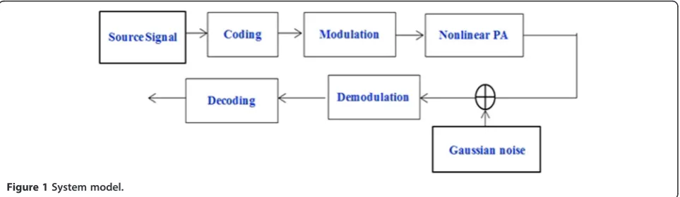
A typical schematic structure of 60-GHz millimeter-wave communication system is given by Figure 1. The source sink generates random binary bits, which are then fed into a coding module where the polar coding and LDPC will be used. Then, the coded signal will pass through a modulation module which will map them into
baseband complex signals based on the prescribed modu-lating method (typically, high-order modulation will be used, e.g., QPSK and 16-QAM). Next, the emission signals will be distorted by a nonlinear PA, and finally, go through the channel by adding complex Gaussian noise in the re-ceiver. In the receiver, the contaminated signals will be demodulated into binary bits and get decoded.
2.1 Nonlinearity of PA
After the modulation, signals passed through a nonlin-ear PA operating in high-frequency bands, the nonlinnonlin-ear distortions will occur inevitably. The bad influences of nonlinearity may lead to the distortions of both ampli-tudes and phases in output signals [7], which may be usu-ally characterized by the amplitude-amplitude (AM-AM) model and amplitude-phase (AM-PM) model signal’s amplitude, respectively. These two mathematical models are specified as below, i.e.:
G Að Þ ¼g A
1þ AgAsat 2s
1
2s ð1Þ
φð Þ ¼A aAq1
1þ Ab q2
ð2Þ
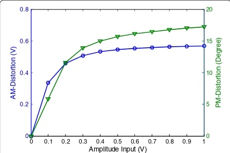
According to the IEEE 802.11ad standard, Aand G(A) represent the amplitude of input and output, respectively, the latter of which has a saturation thatAsat = 0.58, while
g, the linear gain, takes its value at 4.65. Parameters= 0.81 denotes smoothness of the inflection point of distortion. In the latter expression, φ(A) denotes the distortion of PM, and parametersa, b,q1, andq2 take value at 2560, 0.114, 2.4, 2.3, respectively [6].
Figure 2 shows the typical mapping curve of AM-AM and AM-PM regulated by the IEEE 802.11ad, from
which we may note that the distortions will become more obvious with the increasing of input amplitudes.
2.2 Modulation schemes
In this paper, binary phase shift keying (BPSK), quadra-ture phase shift keying (QPSK), 16 quadraquadra-ture amplitude modulation (16QAM), and orthogonal frequency-division multiplexing (OFDM) will be considered for modulation methods. According to Figure 2, the distortions of PSK signals after passing through a nonlinear power ampli-fier (NLPA) can be neutralized by tilting the coordinate axis back, a fixed angel that equals to the distortion of phase, since the PSK signals have the identical ampli-tudes. QAM signals can be also calibrated through a method that proportional reduces the signal’s amplitude into a linear area, which can still maintain a relatively dis-tinguished constellation map for demodulating. Unfortu-nately, OFDM signals, which are extremely sensitive to nonlinear distortions due to its high peak-to-average power ratio (PAPR), may have the worst effect of NLPA distortion since the IFFT process builds an irregular set of OFDM signals.
3 Polar code for 60-GHz communication
A polar code is a kind of GN-coset code inspired by a
phenomenon called channel polarization, which can be achieved by recursively combining with N channel
W :X→Y and then splitting the combined channels intoNchannels through information theory. With this method, the theoretical BER of some channels approach nearly to 0, while the rest of them are close to 1. And the channel capacities among those channels go through oppos-ite directions. Those channels whose theoretical BER are ap-proaching to 0, in other words, whose channel capacities are approaching to 1, are defined as good channels and will be selected to transmit data since the lower the theoretical BER means a better distribution of channel capacity.
We firstly utilize aji to denote a vector (ai,ai+1,…,aj),
where i and j are natural numbers with normally i≤j. Otherwise,ajiis regarded as void whilei > j.
Define a binary-input discrete memoryless channel (B-DMC)W :X→Y, with a fixed input set {0,1}, and an arbitrary output set, is defined as symmetric only when a permutation Π:Y→Y exists, that is, there exists a π makes sense forW(y|0) =W(Π(y)|1) for ally∈Y.
When a fixed W :X→Y is given, I(W) is defined as the mutual information between the input and output of
W :X→Y. I(W) has a spectrum of [0,1], and only when inputs have uniform distribution,I(W) can be considered as the capacity of channel with an expression below:
I Wð Þ ¼X
y∈Y X
x∈X 1
2W yð Þjx log
W yð Þjx 1
2W yð j0Þ þ12W yð j1Þ
ð3Þ 0
0.2 0.4 0.6 0.8
A
M
-Dis
to
rt
io
n
(
V
)
Amplitude Input (V)
0 0.1 0.2 0.3 0.4 0.5 0.6 0.7 0.8 0.9 10 5 10 15 20
P
M
-D
is
tort
io
n (D
e
g
re
e)
Also, Z(W) is defined to quantize the theoretical BER as the Bhattacharyya parameter ofW :X→Yand has an expression as:
And the lower the Bhattacharyya parameter of one channel, the higher the channel capacity it obtains [8].
We regard 1ε= 1 only when a group of variables (x,y)
where Pe(W) is the theoretical BER through maximum
likelihood ratio decoding method. So Z(W) is an upper bound of theoretical BER and can be reduced to improve the transmission performance.
3.1 Channel combining
For any arbitrary positive integerland an l×linvertible matrix F with entries in {0,1}, consider a process that a random l-vector Ul1 with a uniform distribution over {0,1}l firstly multiply the matrix F over GF(2) and then passes through the channelW :X→Yto generate a ran-dom vector of output. LetYl1 denote the output. There-fore, the channel transmission probabilities between Ul1 andYl1can be expressed as below:
Wlðyl1jul1Þ ¼
The process described above is called channel combin-ing and can be illustrated in Figure 3.
Figure 4 illustrates ann-step (N=ln) of channel combin-ation, where input (U1,U2,…,UN) denotes a random vector
of variables while output (Y1,Y2,…,YN) denotes another
vector of variables. RlN is a kind of permutation matrix that reassigns a series of random variables (V1,V2,…,VN)
generated by (U1,U2,…,UN) passing through matrixF.
By operating such process, a combining channel
WN:UN1→YN1 can be created, with the transmission
where vN1;k is a newly generated vector created by per-mutation matrix RlN, a reassignment method that al-ters the order of the random vector VN1 into VN1;k¼ Vk;Vlþk;…;VmlþkÞ;k¼1;2;…;l; ðmþ1Þl≤N<ðmþ2Þl
ð .
Also,uN1; yN1 andvN1 denote a sample ofUl1;Yl1andVN1, respectively.
According to the combination recursive process de-scribed before, prior to reach the finalN-number of W, the input data uN1 can be equivalently transform intoxN1 through a linear transformation, that is:
xN
1 ¼ uN1 GN ð8Þ
where GN is called generator matrix. According to the
combination process in Figure 4, GN can be calculated
recursively as below:
the Kronecker multiplication and G1 represents 1 × 1
unit matrix.
3.2 Channel splitting
We start this part by analyzing the information theory formula below:
I UN 1;YN1
¼XN
i¼1
IðUi;YN1jUi1−1Þ
¼X
N
i¼1
I Ui;YN1;Ui1−1
−I Ui;Ui1−1
¼X
N
i¼1
I Ui;YN1;Ui1−1
ð10Þ
where I Ui;Uð1i−1Þ
¼0 because of the independent sourceUN1.
Define WiN:Ui→YN1 U
i−1
ð Þ
1 ;1≤i≤N as a channel by splitting the combining channelWN:UN1→YN1 based on Equation 10 and calculate transmission probabilities:
Wi
N yN1;ui1−1jui
¼ Pr yN1;ui1
Prð Þui X
uN iþ1
Pr uNiþ1
¼X
uN iþ1
PryN1;uN1 Prð Þui
¼X
uN iþ1
PryN1juN1 Prð Þui Pr u
N 1
ð11Þ
Therefore, by combining the transition probabilities of
Wi
N andWiN=l, the recursive formula is:
Wl i−ð 1Þþj
N yN1;u
l i−ð 1Þþj−1
1 jul i−ð 1Þþj
¼ 1
2l−1 Xuli
ul ið−1Þþjþ1
Yl
k¼1 Wi
N=l yðkN1þ=klÞþN1=l;v
l i−ð 1Þ
1;k j ulil i−ð 1Þþ1F
k
ð12Þ
In Formula 12vilði−1Þlþ1¼uðili−1Þlþ1F, 1≤i≤N/l, and 1≤
j≤l.
Example 1: Arikan’s scheme given that:
F¼ 1 0
1 1
We can calculate a generator matrix GN. with a
specified N= 2n. In order to select split channels for transmissions, Arikan has provided a set of formulas [8] to calculate the Bhattacharyya parameter of each split channel, that is:
Z W2i−1
N
¼−Z Wi
N=2
2
þ2Z WiN=2
Z W2i
N
¼Z Wi
N=2
2
8 > < >
: ð13Þ
As well, when utilizing successive cancellation (SC) de-code method, it may come up with a set of formulas to calculate likelihood ratio,
These formulas are only available for the 2 × 2 matrix
F¼ 1 0
1 1
, however, but not for other specified
matrix, which limits the wide application of polar code. In order to tackle this problem, we first should to iden-tify what kind of matrix has the feature to generate polar code, and this feature referred as to polarization feature.
3.3 Polarization feature
Define Wk :f0; 1g→Yk as a channel with an inputx, outputsyk1and transmission probabilities:
Wk yk X→Y, which has a Bhattacharyya parameter:
Z W k ¼X extent, can improve the transmission performance.
Therefore, a paraphrase is given for channel polarization, F is a polarizing matrix when there exists at least an
i∈{1,2,…,l}, makes sense that:
Some attributes of a polarizing matrix F maybe of interest. When the last row ofFhas k >1 unit elements,
whose subscripts compose a set J= {j1,j2,…,jk}, then the
transmission probability ofWllcan be calculated by:
Wl Accordingly, the Bhattacharyya parameter is given as below: which satisfies Equation 17, and Fl-1 denotes a
sub-matrix ofFby removing its last row.
Consider more general circumstances in which any split channelWll−iwith transmission probability:
Wl−i When the last row ofFhas only one unit element, due to the permutation feature, we assume the unit element is the last element in this row; then, the channel trans-mission probability can be rewritten into:
Wl−i Therefore, the output Yl is independent of inputs to
the channel Wll−i, indicating that the split channels W1l; W2
l;…;Wll−1 are defined on matrixFl−1, which are
ob-tained by removing the last row and last column ofF. Based in a recursive analysis on Fl − i, we may finally conclude that a matrixFdoes not have polarization fea-ture whenFis an upper triangular matrix.
3.4 Two difficulties of a polar code
code that based on any specified matrix. That is, firstly, we need Bhattacharyya parameters of each split channels to select channels for data transmission. Secondly, a group of recursive formulas is demanded as a necessity of preparation to implement decoding scheme, the successive cancellation decode (SC). There come two al-gorithms we proposed, to cope with the two realistic challenges we mentioned.
3.5 Recursive Z algorithm
For a more general case, we firstly propose an algorithm calculating Bhattacharyya parameters by defining c0¼
ui−1
a set of indices that indicate the elements of bothc0and
c1are equal to 1. Therefore, the Bhattacharyya parameter
of each split channelWllcan be calculated below:
Z Wi
Example 2:given a matrix
F¼ 11 00 01
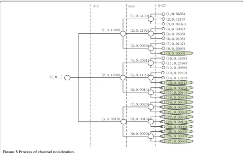
with a BEC channel, according to the recursive Z algo-rithm above, the recursive Bhattacharyya parameters can be calculated below:
Figure 5 shows a three-step process of channel polarization, each knot denotes a split channel and has a vector, in which the left parameter representse number
of split channels, while the right one represents the Bhat-tacharyya parameter. Knots on the right side are the split channels through this three-step polarization, of which the green ones are those good channels selected to transmit data since the lower the Bhattacharyya parameter, the higher the channel capacity they have gained.
Therefore, by generating a 3 × 3 based polar code scheme, we testified the recursive Z algorithm is effective on constructing generalized polar coding scheme, which means as long as we can find a matrix that has a polarization feature, we can realize a new polar coding scheme based on that matrix. It has been testified that in order to gain a higher error exponent than 0.5, the length of a polarization matrix has to be more than 16 [9,10].
3.6 Recursive likelihood ratio algorithm
We define likelihood ratio in SC decode method as below,
where ^ui1−1 denotes the received data whose values have been decided successively, while ûidenotes a
stat-istical decision of ui, whose value has not been decided
yet.
Obviously, through Expression 13, we can literally cal-culate LiNyN1;u^i1−1 , but amounts of complexity accom-panies. Instead, a more efficient FFT-like method is proposed to calculate LiN yN1;^ui1−1
based on the recur-sive feature of polar code.
The likelihood ratio can be rewritten as below:
The numerator and denominator of the right side of Expression 25 can be expressed, respectively:
Yl
Example 3: Consider the matrix given before with a BEC channel:
The recursive form of likelihood ratio based on recur-sive likelihood ratio algorithm can be calculated below:
L3i−2
where:
α¼Li
N=3 yN1=3;u^31;1i−3⊕u^31;2i−3⊕u^31;3i−3
β¼Li
N=3 y2NN=3=3þ1;u^3 i−3 1;3
γ¼Li
N=3 yN2N=3þ1;u^ 3i−3 1;2 ⊕u^31;3i−3
8 > > > < > > > :
According to Equation 29, a FFT-like SC decode method can be created; that is, calculating each LiNyN1;u^i1−1 de-mands only its three ex-step parameters, which recursively, creates a method that has only a complexity ofO(Nlog3N).
4 Experimental simulations
In the experimental simulations, we mainly focus on the line-of-sight (LOS) scenarios, in which the first LOS
path may have an extremely strong energy [11]. This is justified by wide adoptions of beam-forming techniques [12,13]. In this case, the single-path complex Gaussian channel can be used for the simplicity of analysis [14,15]. The sampling rate is relatively high at 60GHz band, which may be further reduced by some recent sig-nal processing techniques, such as sampling conversion [16] or compressive sensing. The code rate is fixed at 1/2, the erasure probability (∈) is 0.1. We give the rest of chan-nels with 0 bits. In the experiments, the classical polar code composed by Arikan (i.e., l= 2), which is denoted by polarcode 2, is also used for comparative analysis. Meanwhile, the popular LDPC scheme, based on a 336/ 672 check matrix, proposed and approved by the IEEE 802.11ad standard [6] has also been adopted.
0 1 2 3 4 5
10-5 10-4 10-3 10-2 10-1 100
QPSK-LPA
NoCode PolarCode3 PolarCode2 LDPC
0 1 2 3 4 5
10-4 10-3 10-2 10-1 100
(Eb/N0)/dB
BE
R
QPSK-NLPA
Figure 8BER performance of QPSK modulated signals.
0 1 2 3 4 5
10-5 10-4 10-3 10-2 10-1 100
BER
BPSK-LPA
0 1 2 3 4 5
10-5 10-4 10-3 10-2 10-1 100
(Eb/N0)/dB
BPSK-NLPA
NoCode PolarCode3 PolarCode2 LDPC
Firstly, a channel polarization histogram based on:
F =
1 0 0
1 0 1
1 1 1
2 4
3
5 is shown in Figure 6. We may notice that
the ratio of Bhattacharyya parameters approaching to 0 is 90%, while the ratio of those channels whose capacities are approaching to 1 is less than 10%. According to the channel polarization theory proposed by Arikan [7], we can conclude that the generalized matrix has the polarization feature and the recursive Z algorithm can be used to effectively calculate Bhattacharyya parameters.
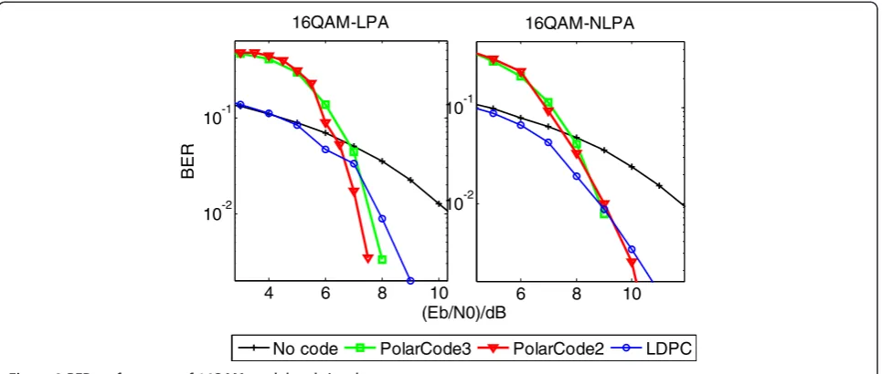
In the simulations, BPSK, QPSK, and 16QAM are then employed. In order to build simulations in an environ-ment of NLPA, the operational voltage on the PA in-puts was defined within a range of (0.3, 1), which, according to Figure 2, can generate nonlinear distor-tion of outputs. The BER performances of these modu-lated signals have been plotted by Figures 7, 8 and 9, respectively. It is obviously noted that the BER per-formance of both the polar code, and LDPC will be significantly reduced, compared with the noncoding situation. There, the coding scheme can be viewed as an effective approach to combat the realistic nonlinear-ity in 60-GHz millimeter-wave communications. Sec-ond, it is seen that, in the considered BPSK, QPSK, and 16QAM signals, the polar code may usually surpass the popular LDPC in high SNR regions. Taking the QPSK signals of SNR = 2 dB, for example, the BER may even approach 8 × 10⁻³. In comparison, the BER value of LDPC is only 4 × 10⁻². Roughly, a detection gain of 0.6 dB can be acquired by the polar code. Third, it is shown that the 16QAM is more vulnerable to 60-GHz nonlinear PAs (NLPAs), compared with other lower-order modulation schemes. Finally, we may note that, in the case of 16QAM signals with NLPA, the designed
polar code seems to be comparative with the class polar code ofl= 2, which (withl= 3), however, may be of more flexibility and efficiency in frame designing and multi-complexity.
5 Conclusion
The transmission performance of 60-GHz mm-Wave communications is significantly vulnerable to hardware impairments, especially the evitable nonlinearity of PA. To deal with such drawbacks, polar code is proposed for 60-GHz systems in this investigation. In order to generalize the originally posed classical scheme that only is applied to a 2 × 2 matrix, a promising recursive Z algorithm and recursive likelihood ratio algorithm are proposed for selecting split channels and SC decoding scheme, which can be then conveniently applied in construction of polar code of any fixed matrix with polarization features. The provided experimental simula-tions have verified the proposed algorithms as well as polar coding schemes, which may obtain more promising BER performance in the presence of either linear PA or nonlinear PA than LDPC scheme and which have a lesser decoding complexity than LDPCs. By significantly redu-cing the BER, polar code schemes may be considered as a potential candidate for the emerging 5G mm-Wave com-munications of extremely high data rates.
Competing interests
The authors declare that they have no competing interests.
Acknowledgements
This work was supported by the National Science and Technology Major Project of the Ministry of Science and Technology of China (2015ZX03004008) and the Natural Science Foundation of China (NSFC) under Grant 61271180.
4 6 8 10
10-2 10-1
(Eb/N0)/dB
BER
16QAM-LPA
No code PolarCode3 PolarCode2 LDPC
6 8 10
10-2 10-1
16QAM-NLPA
Received: 22 September 2014 Accepted: 20 January 2015
References
1. Q Liang, Radar sensor wireless channel modeling in foliage environment: UWB versus narrowband. IEEE Sensors J11(6), 1448–1457 (2011) 2. Q Liang, Automatic target recognition using waveform diversity in radar
sensor networks. Pattern Recognit Lett (Elsevier)29(2), 377–381 (2008) 3. J Liang, Q Liang, Design and analysis of distributed radar sensor networks.
IEEE Trans Parallel Distributed Process22(11), 1926–1933 (2011) 4. Federal Communications Commission. Code of federal regulations, part
15-Radio frequency devices section 15.255: operation within the band 57.0-64.0 GHz. http://law.justia.com/cfr/title47/47-1.0.1.1.12.html 47:1.0.1.1.12.3.236.35, Jan., 2001
5. SK Yong, P Xia, A Valdes-Garcia,60 GHz Technology for Gbps WLAN and WPAN [M](Wiley, Chichester, 2011). pp. 2–5
6. IEEE 802.11ad,Part 11: Wireless LAN Medium Access Control (MAC) and Physical Layer (PHY) Specifications Amendment 3: Enhancements for Very High Throughput in the 60 GHz Band [S], 2012
7. E Perahia, M Park, R Stacey, H Zhang, J Yee, V Ponnampalam, V Erceg, A Bourdoux, C Cordeiro, R Maslennikov, S Shankar, A Maltsev, A Lomayev, C Choi, A Jain, M Hossein Taghavi, H Sampath,IEEE P802.11 wireless LANs TGad evaluation methodology [R]. IEEE 802.11 TGad Technology Report 09/0296r16, 2010: 3–5, 9–15, 2010
8. E Arikan, Channel polarization: a method for constructing capacity achieving codes for symmetric binary-input memoryless channels. IEEE Trans Inform TheoryIT-55, 3051–3073 (2009)
9. S Dong-Min, L Seung-Chan, Y Kyeongcheol, Mapping selection and code construction for 2Am-ary polar-coded modulation. Commun Lett 16, 905–908 (2012)
10. Sasoglu, E Telatar, E Yeh,Polar codes for the two-user multiple access channel, Proceedings of the 2010 IEEE Information Theory Workshop, Cairo, Egypt, January 6–8, 2010
11. RG Gallager,Information Theory and Reliable Communication(Wiley, New York, 1968)
12. S Kato, H Harada, R Funada, T Baykas, C Sum, J Wang, M Rahman, Single carrier transmission for multi-gigabit 60-GHz WPAN system [J]. IEEE J Selected Areas Commun27(8), 1466–1478 (2009)
13. H Xu, K Liu,Research on wireless communication networks in the 60GHz frequency band [C](International Conference on Internet Technology and Applications, Wuhan, China, 2010), pp. 1–4
14. B Li, Z Zhou, W Zou, On the efficient beam pattern training for 60GHz wireless personal area networks. IEEE Trans Wirel Commun 12(2), 504–515 (2013)
15. B Li, Z Zhou, H Zhang, A Nallanathan, Efficient beamforming training for 60-GHz millimeter-wave communications: a novel numerical optimization framework. IEEE Trans Vehicular Technol63(2), 703–771 (2014)
16. G Bi, K Mitra Sanjit, S Li, Sampling rate conversion based on DFT and DCT. Signal Process93(2), 476–486 (2013)
Submit your manuscript to a
journal and benefi t from:
7 Convenient online submission
7 Rigorous peer review
7 Immediate publication on acceptance
7 Open access: articles freely available online
7 High visibility within the fi eld
7 Retaining the copyright to your article