ARDUINO-BASED WIRELESS MOBOT
VISHWANATHRADDI A*, KALYAN CHAKRAVARTHI M*
Department of Electronics Engineering, School of Electronics and Communication Engineering, VIT University, Chennai, Tamil Nadu, India. Email: [email protected]/[email protected]
Increased connectivity and remote monitoring and control mechanisms have revolutionized the field of measurement and automation. The proposed work is to design a system which will integrate a mobile bot with Arduino, and it is also possible with LabVIEW through a gateway to run wirelessly. An autonomous robot vehicle is to travel from source to destination through the wheels which are controlled by processor. This will be helpful launch in the application where human being travel will be difficult to meet the work. The proposed system will be able to follow a path with obstacle avoiding. Further, the vehicle can be integrated with NI instruments and with LabVIEW to make it autonomous. LabVIEW is a graphical programming language gives a platform for the engineers, which is effective and scalable to focus on robotics neglecting the minute implementation details.
Keywords: Arduino Uno board, Motor driver, Hardware in loop, Software in loop, Object recognition, Ethernet networks.
INTRODUCTION
Recent years’ wireless technology making all the things automated and working with internet, which is motivating the students to learn about robotics and work in the field of automation. Wireless mobot that is wireless autonomous robot, which is used in artificial intelligence research dominating in the market. Hence, in recent years’ research is going in wireless mobots. They are so many platforms by which we can design wireless robots using C, C++, and Java. Working of the system depends on the operation of the ultrasonic sensors employed to avoid collision with unwanted obstacles. The two DC motors connect to vehicle will get a signal from the Arduino Uno. The main moto of developing this system will be helpful in the field where human entry will be difficult to trace and to monitor the path. The prime objectives that are associated with installing of robotic system in industries are: To enhance the quality and efficiency, to reduce the labors, to demand huge demand in the market, and to work in harsh environment also. Hence, the microcontrollers will provide a better way to sort these problems. It is also possible to build using LabVIEW. LabVIEW is having the ability to generate, control, and acquire the data; hence, any non-programmer can use LabVIEW to develop their ideas without writing thousands of codes.
LabVIEW is a graphical programming platform which will include front panel and block diagram. Along with LabVIEW platform, NI modules are used for connectivity and for monitoring purpose. NI modules such as gateway and wireless sensor network (WSN) will be used to make the system more flexible for commercial application. Gateway will connect the LabVIEW to WSN which is placed on vehicle. LabVIEW and vision assistant module can be used for image processing and feature extraction which will play an important role in traffic monitoring and security purpose. Since the LabVIEW provides a compressive and scalable platform which will make the design, prototypes and deployment phases, allowing designer to focus the automation by ignoring minute implementation details.
LITERATURE SURVEY
An ArgiBot will able to perform agricultural processes such as seeding, spraying of chemicals, weeding. ArgiBot is controlled by Arduino Mega board with AT Mega 2560 microcontroller [1]. Along with Arduino Raspberry Pi a mini-computer is interfaced to monitor and control the
operation of the robot. The Arduino placed on the bot and the robot will be able to move in any direction. Sensors are placed along with body which will show the depth of the path, and there is a mechanism for plantation and the information will be delivered to next robot using Wi-Fi. The system is not so strong to work in complex field, and range of communication range between the robots will be small. Saraladevi and Sedhumadhavan [2] proposed autonomous four-wheeled robot using Arduino, which will start moving from source to destination point by finding the path, avoiding the obstacle and video streaming. All the parameters will be achieved by Wi-Fi technology avoiding the Bluetooth module. Path is identified by the aggrandized genetic algorithm which is best. Here, they failed to communication range for long distance. Amer et al. [3] developed a two-wheeled robot which is compact and portable with an Arduino which is focused on collision detection, avoidance, and avoid to fall from height using Wi-Fi and Bluetooth module.
A mobile vehicle made by Ugurlu [4] using LabVIEW and embedded hardware. He developed a remote-controlled robot and an autonomous robot using arm processor, and monitoring is done at LabVIEW. The main idea behind this was to explore about the usage of hardware and LabVIEW. He presented Coron robot and luminary microrobot which are based on Arm cortex-M3. Fang and Duan [5] presented system which will identify and extract the features of moving vehicles in LabVIEW. The moto behind their work is to automatically generate and maintain a representation of the background, which can be later used to classify the background and foreground to identify the vehicle. They used the tools available from NI-like NI assistant modules, and in LabVIEW, they kept observation of vehicles. All the concepts are meant to explore the system automatically to for one or other application based on the LabVIEW instead of using other available programming languages.
Changalasetty et al. [6] developed obstacle detection for intelligent robots based on LabVIEW and laser measurement system. Obstacle detection is important in the field of automation and sensing surrounding environment.
They implemented the system with the help of LabVIEW and LMS291 sensor to detect the obstacle. The LabVIEW and LMS291 interfaced with the help of RS232 serial communication port. Graphical user © 2017 The Authors. Published by Innovare Academic Sciences Pvt Ltd. This is an open access article under the CC BY license (http://creativecommons. org/licenses/by/4. 0/) DOI: http://dx.doi.org/10.22159/ajpcr.2017.v10s1.19562
Received: 23 January 2017, Revised and Accepted: 03 March 2017
ABSTRACT
interface makes the LabVIEW software as a powerful tool. This will help in communication network for real-time system implementations. Online PMDC motor monitoring and control through the LabVIEW [7] will be best suited for commercial application purpose. The proposed work by them is a low cost and which will integrate several online processes to monitor and control them over the server using LabVIEW platform. The online transmission of data between the customer and server is developed with the help of build in web server in LabVIEW and TCP/IP protocols. They took the help of data acquisition card for fetching real-time data from the PMDC motor. Parking the vehicles in urban areas is one of the biggest problems for the drivers and vehicle owners. The available multi-storey parking system will provide wide parking spaces for more number of vehicles in a limited space. This kind of parking techniques can be improved by automation Abu and Kornain [8] presented an automatic car breaking system by neural network system through LabVIEW platform. These will show the application of LabVIEW of different kinds of domestic applications. This was based completely on artificial neural network for the application such as parking. They replaced the usual car reverse warning system with the system which will react in an automatic manner based on the distance between vehicle and the obstacle to increase the pressure on the breaking system so that vehicle has to land in a safe way and car will halt. Minimum cost autonomous robot based on the combination of Raspberry Pi a mini-computer, Arduino. Both raspberry and Arduino used to design the vehicle to provide computing power and to control law for execution [9]. The system will provide real-time controlling mechanism. Nowadays, image processing technique for robotic field in common and it is finding a significant role there to make the robot-like human. Person follower based on NI module added flexibility to the system, using which the robot can be controlled and programmed through LabVIEW. Camera mounted on the robot and that is interfaced with NI module (SBRIO-9632). The data from the camera and sensor are received to control the robot movement.
Overall, the survey will reflect the merits and demerits of every work. Most of the robots will fail to communicate for a long-range distance, surface depth measurement since every path we cannot expect to be smooth. These demerits will be focused as future work on this platform.
THE PROPOSED MODEL DESIGN
The proposed concept is very easy, cost effective, and less power consumption. Ultrasonic sensors will be aligning the robot to avoid the collision with obstacles in the path. The model can be operated by Wi-Fi. Every module and all the interfaces are well synchronized. Sensors operate at low voltage, which will make the robot from collision with unwanted objects. When the obstacle is detected, vehicle will trace the path around the object to avoid the collision. Here, we employed Arduino Uno board which is giving in system programming. The Arduino Uno is portable which is having powerful microcontroller such as ATmega 328 which will provide ease of coding and execution of commands. Arduino Uno coupled with motor driver, relay, and ultrasonic sensors to make a complete working model.
COMPONENTS Arduino Uno
Arduino Uno is a microcontroller board based on AT Mega 328 p. The operating voltage will be 5 V, and input voltage is 7-12 V. It is having 14 digital input/output pins out of 6 will provide PWM output and having 6 analog input pins.
It is offered with 32 KB flash memory, 2 KB SRAM, 1 KB EEPROM, and clock speed of 16 MHz. It will communicate using the original STK500 protocol (Fig. 1).
Motor driver DC gear
L293D is a medium power motor driver. It is best suited to drive the DC motors and stepper motors. It is known as L293D motor drive IC.
It can drive four DC motors in one direction or drive two DC motors in both the directions. It is mostly to drive the DC motor in clockwise and anticlockwise direction simultaneously. It can handle small or big motors for robotic applications; it is provided with two enable pins for driving motors. Enable pin will be high states to drive the DC motors. Power supply will be fed to the driver pins, and the two motors will be connected across the driver to run them with input voltage (Fig. 2).
Ultrasonic sensor
Fig. 1: Arduino Uno board
Fig. 2: DC motor driver circuit
HC SR04 is the ultrasonic sensor used in this model. Ultrasonic distance measuring module which will provide 2- 400 cm non-contact distance sensing action. The accuracy of the sensor is up to 2 mm. Operating voltages are 5 V DC and operating current is 15 mA. The operating frequency is 40 Hz, and the measuring angle is 15° (Fig. 3).
WORKING
Fig. 4 shows the block diagram will illustrate about how the component is interfaced with Arduino to form complete system. In the diagram, Arduino is acting as central part by which all the peripherals are controlled and monitored. All the connections are made according to the circuit diagram. Fig. 5 is setup of the proposed concept.
Fig. 5 shows the data flow diagram clearly depicts the working flow of wireless mobot.
When the robot starts moving, the ultrasonic sensor will continuously detect the presence of the object and then calculates the distance between the robot and reflective surface. The information will be processed by the Arduino microcontroller board. The calculated
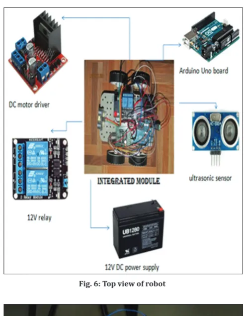
distance is compared with threshold distance mentioned to avoid collision. The rotation will be continued when the distance is greater than the threshold distance. This will be continued along the path and robot keeps on moving with avoiding collision. This robot will move in the prescribed path when the objects come it will stop, and it will go around the object and settles in the same path (Figs. 6 and 7).
RESULTS
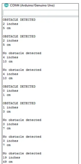
As mentioned in the working procedure, the robot will detect the obstacle whose distance falls below the threshold distance, based on this movement of wheels will go to take place. Figs. 8 and 9 will show the output obtained from the ultrasonic sensor. Through the signals, we can analyze the presence and absence of obstacle. Here, the time interval between the robot and obstacle will be converted to equivalent distance in terms of centimeter or inches.
The standard formula for distance calculation is as follows,Inches=Duration/74/2 and Cm=Duration/29/2. Robot will move and stop based on the threshold distance set to avoid the collision with obstacles.
Fig. 4: Block diagram of system
Fig. 5: Data flow diagram
Fig. 6: Top view of robot
CONCLUSION AND FUTURE WORK
The moto of the project is to study the entire design and working of the wireless mobot, interfacing of the sensors and other peripherals to the microcontroller, and also programming the Arduino. The
output is obtained in Phase I of this stage as expected, where the vehicle tracked the path and also the obstacle avoiding mechanism is met. The system can be made accurate by adding more artificial intelligence to it. Future work that is Phase II will include the design of the mobot using NI instruments and LabVIEW. The designed robot can also be controlled using Wi-Fi or Bluetooth module to make it much more effective.
Future work
The proposed entire system can be designed using NI modules, which will provide a more efficient real-time module. The below block diagram will show the connection between different components of NI modules with LabVIEW. LabVIEW will provide huge accelerated productivity, rapid prototyping, and scalability for the system (Fig. 10).
NI WSN 3212
In the proposed system, NI WSN 3212 is used which is a four channel and 24 bit thermocouple input device which is more sensitive for the analog inputs. It is low power device which will work with gateway to form WSN. We can connect the sourcing digital output to NI WSN 3212 in either drive high only mode or drive high/low mode. There are so many WSN available from the NI which is specific for application. All these work with lower bandwidth range (Fig. 11a).
NI gateway 9792
Gateways are called protocol converters which can operate at any network layer. Any servers which will be acting as gateway are called as proxy server and firewall server. Gateway will contain devices such as protocol.
Translators, impedance matching devices, rate converters, and signal translators which are necessary to provide system interoperability. NI gateway 9792 has serial port RS-232 to which we can connect the devices (Fig. 11b).
Fig. 8: Result window 1 of obstacle detection
Fig. 9: Result window 2 of obstacle detection
Fig. 10: Block diagram
Fig. 11: NI modules (a) NI WSN 3212 module, (b) NI gateway 9792 b
Applications
Wireless mobot can be used in navigation system; household purpose such as vacuum cleaning with much more added artificial intelligence to the proposed system, these kinds of vehicles can be installed in dangerous environment where the human entry is impossible.
REFERENCES
1. Mandal S, Saw SK, Maji S, Das V, Ramakuri SK, Kumar S. Low Cost Arduino Wi-Fi Bluetooth Integrated Path Following Robotic Vehicle with Wireless GUI Remote Control, St. Mary’s Technical Campus Kolkata, India, International Conference on Information Communication and Embedded System ICICES; 2016.
2. Saraladevi B, Sedhumadhavan S. Video Streaming in Autonomous Mobile Robot Using Wi-Fi, Sri Manakula Vinayagar Engineering College Sri Manakula Vinayagar Engineering College Pondicherry India, IEEE Sponsored ICIIECS’15.
3. Amer G, Mudassir SM, Malik MA. Design and Operation of Wi-Fi Agribot Integrated System, Deccan College of Engineering and Technology, Hyderabad India, 2015 International Conference on
Industrial Instrumentation and Control (ICIC) College of Engineering Pune, India May; 2015.
4. Ugurlu Y. Project-based Learning using LabVIEW and Embedded Hardware, Member, IEEE, Tatsuro Nagano, SI International; 2011. 5. Fang Z, Duan J. Obstacle Detection for Intelligent Vehicle based on
Labview and Laser Measurement System, Proceeding of the IEEE International Conference on Information and Automation, Yinchuan, China, August; 2013.
6. Changalasetty SB, Badawy AS, Ghribi W, Thota LS. Identification and Feature Extraction of Moving Vehicles in Labview, International Conference on Communication and Signal Processing, April 3-5, IEEE India; 2014.
7. Kumar KN, Singh N, Kulkarni A. LabVIEW based Online Monitoring and Control of PMDC Motor Speed, New Delhi, India, Electrical Engineering Department, Delhi Technological University, IEEE; 2014. 8. Abu MA, Kornain Z. Automated Car Braking System Using Neural
Network System Via Labview Environment. Selangor, Malaysia: University Kuala Lumpur British Malaysian Institute; 2012.