R E S E A R C H
Open Access
Efficient message exchange protocols
exploiting state-of-the-art PHY layer
João S. Lemos
1,2, Francisco A. Monteiro
1,3*, Ivo Sousa
1,2and Filipe E. Ferreira
1Abstract
The paper focuses on the two-way relay channel (TWRC) and the multi-way wireless network with three terminals, where all three want to exchange or share data and have to do that with the help of a relay. This paper shows how it is possible to significantly decrease the number of time slots required to exchange messages between terminals in networks based on time-division multiple access (TDMA), by taking into consideration new techniques at the physical (PHY) layer. The paper considers a PHY layer where physical-layer network coding (PLNC), multiple-input
multiple-output (MIMO), and in-band “full-duplex” (IBFD) with loopback interference cancellation are all integrated, so that it is possible to significantly increase the overall throughput of the network. This is entirely attained by
transferring the burden from the time domain to the spatial domain, via spatial multiplexing and by simultaneously resorting to non-orthogonal multiple access, which is the consequence of using both PLCN and IBFD. For the TWRC, it is shown that, if a massive MIMO relay is used, a simple lattice-based PLNC can be directly applied and, with typical IBFD interference cancellation amounts, a TWRC can effectively use only one time slot instead of the four needed when adopting the traditional TDMA exchange. In the case of the Y-network (i.e., with three terminals), a technique is presented that allows all the information exchange between terminals to be cut from the six time slots required in TDMA to only one time slot, provided that the information packets are not too short. The error performance of these systems is measured by means of simulation using MIMO Rayleigh fading channels.
Keywords: Y-network, Two-way relay channel, MIMO, Massive MIMO, Full-duplex, Physical-layer network coding, Packets exchange, Interference suppression
1 Introduction
In wireless networks where a relay node intervenes, the traditional way of exchanging messages (symbols or packets) between two or more terminals either involves time-domain multiplexing (TDMA) or dedicated frequency-domain disjoint channels, at the expense of high bandwidth inefficiency. Interference in wireless net-works has been until recently considered a central prob-lem and has been mostly avoided in order to facilitate transmissions between the nodes of a network. For that reason, simultaneous transmissions are treated carefully, so that the interference between users is strictly avoided,
*Correspondence: [email protected]
This paper was partially presented at the18th IEEE Region 8 Mediterranean Electrotechnical Conference (MELECON 2016), Limassol, Cyprus, 18–20 April, 2016, and at the9th IEEE Sensor Array and Multichannel Signal Processing Workshop (IEEE SAM 2016), Rio de Janeiro, Brazil, 10–13 July, 2016. 1Instituto de Telecomunicações, Lisbon, Portugal
3ISCTE—Instituto Universitário de Lisboa, Lisbon, Portugal Full list of author information is available at the end of the article
and this has been contributing to the limitation of the capacity of commercial networks. Wireless networks usu-ally employ scheduling algorithms over the time and fre-quency resources so as to achieve the aforementioned goal. However, with a proper characterization of the inter-ference, these resources may be more efficiently used, thus, enlarging the amount of information exchanged in wireless networks. For that reason, interference may be seen as nothing more than the superposition or sum of delayed and attenuated versions of the user’s transmit-ted signals, and therefore, it can be “decoded”, rather than entirely avoided.
Higher data rates and lower latencies are two central objectives when advancing wireless networks, but while the role of interference at the physical (PHY) layer of wire-less networks has recently been profoundly re-thought with the emergence of new techniques to combat and exploit it in order to maximize the efficiency of the physi-cal resources [1], most of these advances in the PHY layer
of wireless communications have not yet been translated to the way that message exchange protocols make use of the PHY layer [2, 3].
Some of these recent developments in the PHY layer are (i) physical-layer network coding (PLNC), based on the idea that information packets can be superimposed and still recovered as long as the receiver knows part of the information that was superimposed; (ii) multiple-input multiple-output (MIMO) terminals and relays, which allow to boost the time-usage efficiency by transferring the burden from the time domain to the spatial domain, exploiting the spatial multiplexing permitted by having multiple antennas at the terminals; (iii) massive MIMO, where a very large number of antennas create an impor-tant channel orthogonality; and (iv) in-band “full-duplex” (IBFD) technology, which allows terminals and relays to transmit and receive at the same time in the same fre-quency band by applying several layers of loopback inter-ference (LI) cancellation. In the case of IBFD, one very important line of research to further increase the sum-rate of a system is the optimization of the transmission powers of the relay and terminals [4] or just the one at the relay [5]. All these techniques will be central in the next generation of the PHY layer of wireless communica-tions [6], and Section 2 will overview each one of them. In fact, even the medium access control protocols can benefit much from redesigning the protocol taking into con-sideration multi-carrier modulations such as orthogonal frequency-division multiplexing (OFDM) [7].
This paper starts by looking at the two-way relay chan-nel (TWRC), where two terminals, for some reason, cannot directly communicate (e.g., due to propagation obstacles or power limitations) and are forced to exchange data via a relay. It is well known that the number of time slots required to exchange the information between the two terminals can be brought down from four time slots to just two [8]. By deploying a relay using a mas-sive array, a lattice-based PLNC scheme becomes possible and, by applying recently developed cancellation tech-niques for the self-interference, IBFD also becomes possi-ble, allowing the scheme to be able to ultimately exchange information across the TWRC using only one time slot. Note that this contrasts with the four time slots that would be needed in a conventional TDMA-based TWRC. The paper considers the joint application of the three aforementioned technologies at the PHY layer. It should be highlighted that the orthogonal properties of having massive MIMO at the relay are conjugated with PLNC, allowing to increase the amount of information exchanged per channel use and also contributing to further cancel the LI at the relay. Furthermore, with massive MIMO, a simple orthogonal lattice-based PLNC scheme becomes possible, and the dependency of the system’s performance on the number of antennas at the relay is assessed.
Secondly, the paper considers the extension to three ter-minals, which is sometimes named in the literature as the Y-channel [9, 10], and in this paper will be referred to as the Y-network. It comprises three terminals communicat-ing with each other with the help of a relay and can be regarded as a generalized network model of the TWRC for three different users, when the terminals cannot phys-ically establish direct connections among them and where each terminal has some information that wants to trans-mit to the other two. With the advent of MIMO, network coding, and later PLNC, it became possible to reduce the number of time slots required to exchange the informa-tion among all the terminals. To that end, two strategies have been proposed in [11, 12], and those reduced the six slots required in traditional TDMA to three slots and then to two slots only.
In this paper, IBFD is incorporated both at the terminals and at the relay together with PLNC and MIMO, in order to attain the maximum throughput in each of the two wireless network configurations described above. One will consider that some interference is suppressed at the phys-ical layer, while some of it persists and impairs the layers above. The strategies proposed in this paper are able to, on average, reduce the communication stages to a single time slot per message exchanged. The error performance of the systems is determined by means of simulation using flat Rayleigh fading channels.
The paper is organized as follows. Section 2 gives an overview of the main PHY techniques that will be considered in the networks later assessed. Sections 3 and 4 respectively present the proposed strategies for the exchange of information in the TWRC and in the Y-network. The performance results obtained by simula-tion are provided in Secsimula-tion 5, which is followed by the conclusions in Section 6.
2 Modern signal processing at the physical layer
allocated frequency band, when it is compared with the current half-duplex or out-of-band “full-duplex” modes. However, since both frequency and time resources are used simultaneously, the limitations of IBFD operation arise from the existing self-interference, which reflects the leakage of the transceiver’s outgoing signal to its recep-tion side, a problem that is enhanced by the high power unbalance between both signals, hence, potentially caus-ing inadmissible levels of interference that deteriorate the system’s performance [13]. Self-interference must there-fore be mitigated, and this is typically done at three differ-ent independdiffer-ent stages [14]. The first cancellation stage is performed within the wireless propagation domain, essentially by using passive techniques that can electro-magnetically isolate signals. Then, analog radio circuits are employed at a broadband level to further reduce the self-interference signal power. These circuits create a delayed and phase-rotated version of the outgoing sig-nal that is subtracted to the incoming one, aiming at tracking and simulating the effect of the channel [15]. Finally, the third (digital) stage is required in the signal processing domain in order to provide a fine mitigation of the residual interference still present after the first two steps [5].
Another cornerstone technology in 5G is the use of massive MIMO arrays (possibly employing hundreds of antennas) at the base stations and relays, which allows serving more users, i.e., increasing the overall system’s capacity. Theoretically, using aN×NMIMO system can increase byNthe system throughput (for example, by tak-ing advantage of a stak-ingle-valued decomposition (SVD) of the channel and using adequate precoding) [16]. Massive MIMO upscales the attractiveness of MIMO by reducing noise, fading, and interference [17].
Finally, PLNC has emerged as a new way of thinking interference in multi-hop networks. The idea is to treat multi-user interference as a necessary effect, rather than avoid it by allocating different channel resources to differ-ent users [18, 19]. PLNC applies the principle of network coding [20] taking in consideration the additive prop-erty of wireless channels and was simultaneous proposed in three independent works [21–23]. With a sufficient number of linear combinations of messages, it is possible to recover all the messages. Afterwards, a more prac-tical approach to the problem emerged, which explores the capacity of a relay to decode a combination of sym-bol constellations [24, 25]. Also, an information theoretic approach emerged, taking advantage of codebooks and lattice network coding [26, 27].
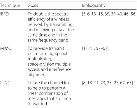
Table 1 presents a summary of the aforementioned PHY layer techniques, as well as related bibliography for further reading.
There is also the possibility of employing massive MIMO arrays in order to cope with the self-interference
Table 1PHY layer techniques
Technique Goals Bibliography
IBFD To double the spectral efficiency of a wireless network by transmitting and receiving data at the same time and in the same frequency band
PLNC To use the channel itself to help to perform a linear combination of messages that are then forwarded
[8, 18–21, 23, 25–27, 62–65]
present in IBFD terminals. The orthogonality property of these large-scale channels allows a better level of mit-igation in the self-interference component. In [28], it is proven that massive MIMO renders more resilience in terms of inter-pair interference, while also mitigat-ing the self-interference effect. The authors proposed a zero-forcing (ZF) precoding and an extended regularized channel inversion that is proven to exploit and combine the advantages of massive MIMO systems and in-band “full-duplex” transmissions. In [29], filtering suppression (which takes advantage of MIMO systems to perform fil-tering) and time-domain cancellation (which subtracts an estimation of the interference from the received signal) are compared; the authors evaluated a bidirectional stream of communication and compared null-space projection schemes with time-domain cancellation having the same degrees of freedom. The methods are compared based on the achievable rates, and they concluded that time-domain cancellation have better achievable rate regions for the channel model considered. Additionally, they observed that antenna imbalance, i.e., having more anten-nas to transmit than receive or vice-versa, can improve suppression methods. In [30], the same authors presented a paper based on MIMO transmission links with loop-back interference suppression decode-and-forward (DF) scheme, which means that the relay fully regenerates the digital signal.
(MRC/MRT) detection and precoding. The multipair of users are seen as a distributed multiple-input transmit-ting to the multiple-output relay. Thus, a linear ZF or MRC detection algorithm decodes the received signal. Since linear decoders can perform as well as non-linear ones with large arrays [31], the outgoing signal is pre-coded with a corresponding ZF or MRT and forwarded. The authors show that when the relay input and out-put antennas tend to infinity, the LI becomes orthogonal with the desired signal, perfectly canceling its undesired effect. Moreover, an optimization of the power alloca-tion is developed, where the system energy efficiency (EE) is maximized, only subject to a given spectral efficiency and peak power. Nevertheless, their results assume perfect channel state information (CSI) for the large-scale fading components of the channels, and for that reason, inter-ference will always be present, albeit, with a low power component.
Few works combining in-band “full-duplex” and PLNC exist in the literature. Zheng has proposed a system for the TWRC [32], where both the relay and the users have multiple antennas. An analog network coding (ANC) to forward information with a ZF constrain at the relay was proposed there, in order to attenuate the problem of self-interference. Moreover, the author presents power control to optimize the system’s rates. Tedik and Kurt have presented a system that utilizes DF relaying based on maximum likelihood (ML) estimation of the XOR func-tion for binary pulse shift keying (BPSK) [33]. The self-interference from “full-duplex” transmissions at the nodes and at the relay are canceled with antenna separation at the propagation level and with time-domain cancellation at a digital level. Very recently, techniques mostly used in sensor fusion were applied to the TWRC with PLNC [34]. These ideas remain valid in the most simple lattices one can think of: the orthogonal lattices, which allow an orthogonal basis. In this paper, one will leverage on the fact that massive MIMO allows to naturally com-municate over such an orthogonal structure, permitting
a quite elegant application of lattice-based PLNC. As a step forward, this paper will then combine PLNC with in-band “full-duplex” transmissions. As already mentioned, TDMA-based exchange of information in the TWRC is accomplished in four time slots. Network coding reduces this number to only three slots. PLNC further improves the exchange of information to two time slots. Finally, by incorporating IBFD, only one time slot may be used to sustain bidirectional streams of information. This could be the major step towards finding solutions to meet the requirements of future networks.
The paper considers a central relay with two or three users who want to send their message to all the other users in the network. The first case, to be described in Section 3, corresponds to the TWRC and the second to the Y-network, which will be described in Section 4. In both cases, the terminals transmit and receive simultaneously and in the same frequency band.
3 The two-users case: the TWRC
In the two-terminal case, the MIMO relay is considered to have a massive array, and one also considers that the two terminals operate a IBFD mode. Given that the sys-tem is symmetric, only the performance of one of the communication directions is assessed.
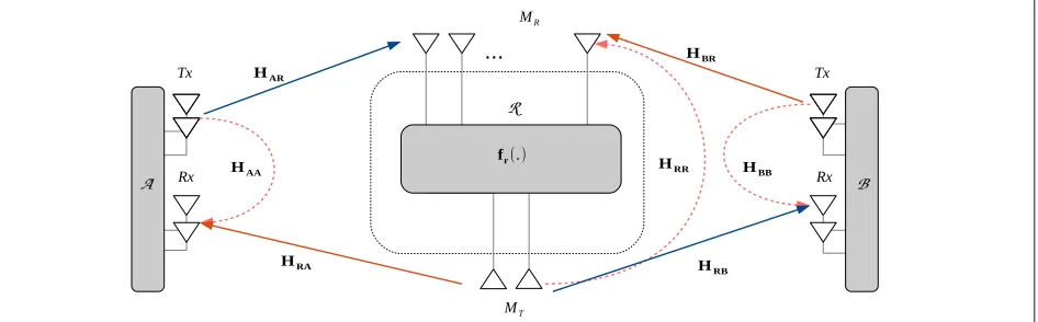
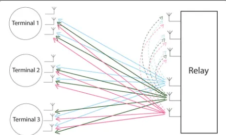
Consider that a terminal A and a terminal B, both terminals with NT receive and NT transmit antennas, exchange information via a relay station R, which is assumed to have MR >> NT antennas to receive and MT =NTantennas to transmit, as Fig. 1 depicts.
The received signals at each element at time slotnof the system are expressed by:
yR(n) =√pAHARxA(n)+√pBHBRxB(n) (1) + √pRkRHRRxR(n)+nR(n),
yA(n)=√pRHRAxR(n)+√pAkAHAAxA(n)+nA(n),(2)
yB(n)=√pRHRBxR(n)+√pBkBHBBxB(n)+nB(n),(3)
wherexA(n),xB(n)andxR(n)are the terminalA, terminal
Band relay transmit signals, respectively. MatricesHAR∈
CMR×NT,H
BR ∈ CMR×NT,HRA ∈ CNT×MT andHRB ∈
CNT×MT represent the channels fromAandBtoR, and vice-versa. MatricesHAA∈CNT×NT,HBB∈CNT×NTand
HRR∈ CMR×MT represent the self-interference channels,
while nA(n), nB(n) andnR(n) account for the complex
circularly symmetric Gaussian noise vectors. The trans-mit average power of the elements involved in the system are given by pA, pB and pR, respectively. Furthermore, the self-interference is mitigated through parameterskA, kB and kR, that translate the suppression levels, with respect to the situation without interference. The residual interference (i.e., the discrepancy between the estimated interference and the real interference) is modeled as:
HAAxA(n)−HAAxA(n):=kAHAAxA(n),
HBBxB(n)−HBBxB(n):=kBHBBxB(n),
HRRxR(n)−HRRxR(n):=kRHRRxA(n),
(4)
whereHAAxA(n), HBBxB(n)andHRRxR(n) are the
esti-mations of the self-interference components at terminals AandBand relayR, respectively. Typical values forkA,kB andkRhave been considered for different types of signal processing canceling techniques in [33, 35].
The PLNC concept is specially suitable to enhance the throughput of the TWRC scenarios [2, 19, 36], where two terminals exchange data with the help of a relay. In the traditional TWRC setup, one terminal would send its message to the relay in the first time slot, the other ter-minal would use the second time slot for its message and the relay, after applying network coding, would send in the third time slot, the sum of the previously received signals. As the relay only needs the sum of the messages, by using PLNC, the terminals can transmit their signals simulta-neously to the relay, in the same time slot, and the relay would then send this sum of the signals in the following time slot, hence, reducing the total required number of communication stages to only two time slots [19, 36].
A particular form of PLNC that is based on lattices, and which is dubbed compute-and-forward (CF) [23, 26], is implemented in this paper using the algebraic approach proposed in [27]. The main concept is that the relay for-wards a function of the superimposed received symbols and that an isomorphism exists between the transmitted codewords and the symbols mapped onto a lattice. The idea relies both on the closeness of group codes under addition and on the additive superposition of electro-magnetic waves. Due to these properties, after receiving a combination of the sent codewords and by knowing its own codeword, a terminal may be able to decode
the incoming codeword from the other pair. In prac-tice, this isomorphism is framed by using nested lat-tice codes [26], whose codewords are constructed in the following manner:
L=F∩VC= {λ=[λF] modC,λF∈F},
where F is a fine lattice that falls within the funda-mental Voronoi region,VC, of a coarse lattice,C, and
where modreturns the quantization error with respect to[37].
3.1 Nested lattice code
Within the algebraic framework of [27], each terminal generates data streams from a two-dimensional integer set with field sizeQ=3, i.e.,SA,i,SB,i∈Z23, fori=1,. . .,NT, which are then mapped ontoxA,xB,∈CNT, with function
φ:Z23→L=F∩VC(∈C),
SA,i,SB,i→xA,xB.
(5)
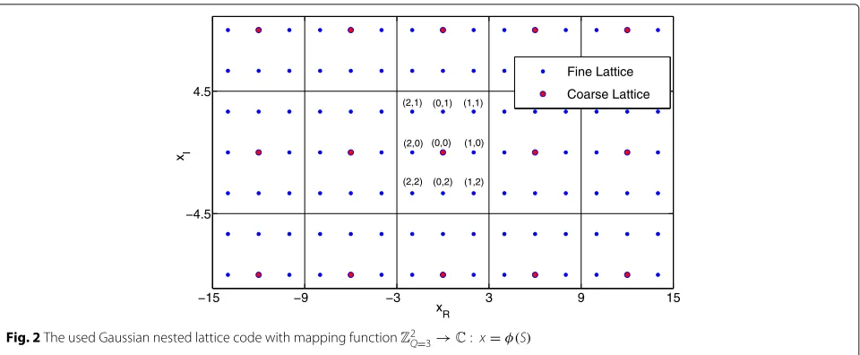
A fine Gaussian lattice is considered, defined as
F = {x ∈ C : x = 2z1+j3z2; z = (z1,z2) ∈ Z2}, and a functionφ(·)is defined such that the transmitted codewords from each antenna of each are mapped onto
{(0, 0),(0, 1),(0, 2),(1, 0),(1, 1),(1, 2),(2, 0),(2, 1),(2, 2)} ∈
Z2
3onto the points{0+0j, 0+3j, 0−3j, 2+0j, 2+3j, 2− 3j,−2 +0j,−2+3j,−2−3j} ∈ C, carving a so-called 9-QAM constellation as the one in [27], defining the nested lattices depicted in Fig. 2. It should be noted that before transmission, the lattice points are normalized to unit power.
3.2 Protocol for the TWRC
A major consequence of using massive MIMO is the so-called channel hardening effect [38] resulting from the fact that Gaussian vectors randomly selected in large dimensional space are, with high probability, nearly orthogonal. Due to this effect and by using the mappingφ defined in Section 3.1, it will be shown below that the task of the relay in the CF protocol becomes the one of finding an integer combination of the transmitted symbols at time slotn, in the form:
DAxA(n)+DBxB(n)
modC, (6)
whereDA,DB∈ZNT×NTare diagonal matrices with
inte-ger entries forming the network code that interprets the effect of a complex channel as an integer one. The relay starts by applying a ZF filter to remove the interference, defined by HAR† + HBR†
−15 −9 −3 3 9 15 −4.5
4.5
x
R x I
Fine Lattice
Coarse Lattice
(0,2) (0,0) (2,0) (2,1) (0,1)
(1,2) (1,1)
(1,0)
(2,2)
Fig. 2The used Gaussian nested lattice code with mapping functionZ2
Q=3→C: x=φ(S)
induced by the massive array, this is in fact a quasi-optimal approach [17]. Therefore, the pseudo-inverses ofHARand
HBRare calculated, and the received vector at the relay is
given by:
yP(n)=HAR†yR(n)+HBR†yR(n) (7) =HAR†HARxA(n)+HBR†HBRxB(n)
+
HBR†HARxA(n)+HAR†HBRxB(n)
+
HAR†+HBR†
kRHRRxR(n)+nR(n)
=DAxA(n)+DBxB(n)
desired component
+ n ˜R(n)
equivalent total noise ,
whereyP(n)∈CNT×1is the desired linear combination of
the terminals’ signals that arrive at the relay. Additionally, without loss of generality, one considers the case where the transmit power of both terminals and the one of the relay arepA = pB = pR = 1. It is interesting to look at the equivalent noise in (7) given the noise enhancement caused by ZF. The simplifications are a consequence of the channel hardening effect, which ensures all the follow-ing asymptotic properties for the matrices:HAR†HBR →
0, HBR†HAR → 0, asMR→ ∞. Furthermore, the self-interference is also mitigated due to the orthogonality betweenHAR+HBR
†
andHRR, while ZF detection in
massive MIMO does not lead to a large noise enhance-ment, in contrast to what happens in conventional MIMO. The proposed CF protocol for IBFD relaying with massive MIMO is detailed in Algorithm 1, describing the process-ing that is performed both at the relay and at the two terminals. It should be noted again that when the relay transmits, it only uses MT = NT antennas, such that HRAis symmetric and full-rank with high probability. The
performance of this scheme will be assessed in Section 5.
Algorithm 1PLNC Scheme for Massive MIMO Relaying Processing stage at the relay for each yR(n):
1) Zero forcing processing of the received signal: yP(n)=HAR†yR(n)+HBR†yR(n);
for i=1,. . .,NTdo
2) Quantize the symbol at each antennayP,i to the closest lattice point inF: QF(yP,i);
3) Recover a point belonging to the nested lattice code:xR,i=[QF(yP,i)] modC.
end for
4) Transmit the signalxR(n)=[xR,1,. . .,xR,NT]T; Processing stage at terminalA(analogous for termi-nalB):
1) Decode the relay transmitted signal: xˆR =
arg minλ∈(
F∩VC)NT yA−HRAλ; for i=1,· · ·,NT do
2) Map the information from each complex dimen-sion back to the finite field, for each dimendimen-sion:
u1,i = φ−1(R(xˆR,i)) =[SA,1,i +SB,1,i] modQand u2,i=φ−1(I(xˆR,i))=[SA,2,i+SB,2,i] modQ;
3) Subtract own information to obtain:SˆB,1,i=[u1,i− SA,1,i] modQandSˆB,2,i=[u2,i−SA,2,i] modQ; end for
4) ObtainSˆB,i =(SˆB,1,i;SˆB,2,i)fori=1,. . .,NT.
4 The three-users case: the Y-network
4.1 Configurations for message exchanging
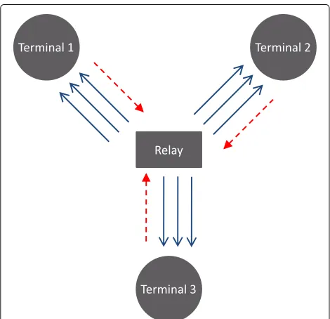
The Y-network adopted in this work is depicted in Fig. 3, depicting the messages that are exchanged in the case of a TDMA operation mode. In that case, the relay needs to receive three messages, each of which coming from a dif-ferent terminal (dashed red lines), and it later needs to broadcast each of them, so that each user gets the two messages that it still does not know from the other two users (solid blue lines), amounting to a total of six time slots for the message exchanging process to take place.
When using the multiple-access channel (MAC) phase of the schemes proposed in [11], one creates a virtual-MIMO uplink with three streams (one from each terminal to the relay), where the relay receives the incoming sym-bols from the three terminals using three antennas. In the proposed setups, both the relay and the terminals have extra antennas to support IBFD: the relay is equipped with three receiving antennas and three transmitting anten-nas, using the so-called natural isolation between transmit and receive antennas, using radio frequency (RF) cancel-lation, and finally counting on signal processing to assure the remaining signal cancellation [5, 35, 39, 40]. On the other side, each terminal has one transmitting antenna and either one or two receiving antennas (for MIMO reception in the latter case). In fact, two different con-figurations for the terminals’ side will be studied, while at the relay three receiving antennas and three transmit-ting antennas are considered in both configurations. The first configuration, denoted hereafter as configuration A, considers terminals with one receiving antenna and one transmitting antenna, so as to enable IBFD (Fig. 5). The
Fig. 3The Y-network configuration with three terminals and one relay
second configuration, denoted as configuration B, com-prises the same number of antennas at the relay, but each terminal has now two receiving antennas (Fig. 6), enabling MIMO detection in the downlink (from the relay to each terminal).
Figure 4 illustrates the transmission phase from the IBFD terminals to the relay. Figures 5 and 6 show the broadcast phase, when the relay transmits to the terminals while suppressing LI at the relay; Fig. 5 shows the setup with two receive antennas at the terminals, and Fig. 6 shows the setup with three receive antennas. In all these three figures, the LI is represented by the dotted lines, which sets this model apart from the one in [11].
Before looking into the details of the system model, as it will be detailed in Section 4.2, one starts by looking at the overall process of exchanging messages when employ-ing IBFD with configuration B, as depicted in Fig. 7. In this configuration, the receiver is able to detect the two unknown incoming messages, given that it already knows its own message and can cancel it out using the PLNC principle. The arrows in Fig. 7 are associated to the mes-sages exchanged along the successive time slots, wherexi,j represents a message sent from terminaliduring time slot j. In the first time slot, the relay does not have anything to send to the terminal, and for that reason, it remains silent. After this initial stage, the transmit antennas of the three terminals and the ones of the relay are all sending data streams, resulting on an average of one time slot per infor-mation exchange. It should be noted the delay of one time slot in the downlink regarding the information that is sent in the uplink.
4.2 PHY signaling and detection
For a given time slotn>1, the signal received at the relay is
y(n)=H(n)x(n)+n(n)+HLI(n)xˆ(n−1), (8)
Fig. 5Downlink phase with “full-duplex” (configuration A)
wherey(n) = y1(n),y2(n),y3(n)
is the received signal vector, xn = [x1(n),x2(n),x3(n)] denotes the trans-mitted signal vector,H(n)stands for the channel matrix where each entry hi,k(n) represents, as before, the link between the transmitting antenna of thekth terminal and theith receiving antenna of the relay,n(n)corresponds to the noise vector,xˆ(n−1)=xˆ1(n),xˆ2(n),xˆ3(n)
denotes the previously detected symbol at the relay and HLI(n) stands for the channel matrix of the LI at the relay. On the other hand, the signal that each terminal receives in the same time slotnis given by
y(n)=H(n)xˆ(n−1)+n(n)+HLI(n)x(n) (9) where y(n) represents the received signal vector with NT complex dimensions (i.e., NT antennas),n(n) corre-sponds to the noise vector andHLI(n)denotes the channel matrix of the LI at the terminals. Note that (9) still holds for the case withNT =1 in configuration A, although in that case all vectors become scalars.
The LI contribution in both (8) and (9) cannot be neglected and leads to a performance loss; hence, some type of isolation (physical and electrical) must be added between the corresponding pair transmitting/receiving
Fig. 6Downlink phase with “full-duplex” (configuration B)
antenna. Similarly, to the TWRC model in (4), the resid-ual LI will be represented by aK factor, withK < 1, as considered in [33], i.e., a lowerKvalue represents a larger reduction of the self-interference, yielding the following updated expressions:
y(n)=H(n)x(n)+n(n)+KHLI(n)xˆ(n−1) (10) y(n)=H(n)xˆ(n−1)+n(n)+KHLI(n)x(n). (11) Each element of the different channel matrices is taken from a zero-mean circularly symmetric complex Gaussian distribution with unit variance, and the noise compo-nents are drawn from an independent circularly symmet-ric complex Gaussian with zero average and varianceσn2. It is also assumed that the channel state information at the receiver (CSIR) is available and that, as reflected in (10) and (11), all the links between terminals and the relay are reciprocal, i.e., they are the same in the uplink and downlink phases (when this assumption is verified in real systems, it simplifies the channel estimation phase). Stan-dard M-ary squared quadrature amplitude modulation (M-QAM) constellations are used to transmit the differ-ent messages. The symbols are taken from a finite complex constellation C constructed from the Cartesian product C=CR×CR, whereCRis the real set
CR=
−√M−1,. . .,−3,−1,+1,+3,. . .,+√M−1.
(12)
Without loss of generality, the filters adopted for the performance assessment at the receivers have a normalized impulse response h(t) such that
|h(t)|2dt=1.
Finally, the symbol error rate (SER) of the downlink phase is obtained by comparing the messages decoded at each terminal or relay with the original messages sent by each of them in the uplink phase. For the case of the relay, the signal-to-noise ratio (SNR) is defined by
SNR=
Ey(n)y(n)
En(n)n(n)+K2Exˆ(n−1)H(n−1)H
LI(n)xˆ(n−1) ,
(13)
as in similar IBFD systems [33]. Likewise, a similar expres-sion can be written for the terminals’ side. Note that the downlink performance accumulates the errors occurred during the two phases, i.e.,
SERtotal=1−(1−SER)2. (14)
4.3 Protocols for the Y-network
Fig. 7Messages flow between the terminals and the relay using configuration B (terminals with two receiving antennas)
In the uplink phase, the same strategy is used for both configuration A and configuration B, using virtual MIMO: the signals are transmitted simultaneously by the three terminals, and the relay applies a robust detection tech-nique such as a lattice reduction-aided (LRA) detector, followed by ordered successive interference cancellation with minimum mean square error (OSIC-MMSE) [41]. It is well known in the MIMO literature that the perfor-mance attained with LRA captures the full diversity order available in the MIMO spatial multiplexing, i.e., the slope of the SER curves is the same as the one provided by the ML detection, although they exhibit some power penalty in respect to the ML performance curves. The option for this type of MIMO detection algorithm is due to the fact that lattice-based receivers are until now the best compromise between computational complexity and per-formance [41]. At the end of this MIMO detection phase, the relay has detected the messagesx1,x2andx3; this pro-cedure consumes one time slot in the overall messages exchanging process.
The downlink phase in configuration A consists of the following three steps during the broadcast phase:
Step 1: The relay first broadcasts the estimates of the signal received during the previous time slot (i.e., during the MAC phase).
Step 2: Using the PLNC principle, each terminal receives the above overlapped messages and cancels its own additive contribution (given that each terminal knows the signal it has previously transmitted, as well as the channel response, assuming CSIR).
Step 3: Each terminal estimates the two remaining messages of the other two terminals performing a joint ML detection for those two remaining symbols.
During the downlink phase of configuration B, the first cancellation described for configuration A (in step 2) is performed in the same manner at all the three terminals; however, since two antennas are used for reception in configuration B, the remaining detection problem can be seen as a 2 × 2 MIMO spatial mul-tiplexing problem, which can be dealt with by one of the many different detection techniques, according to
the complexity-performance tradeoff one needs and is able to afford [41]. For this purpose, LRA OSIC-MMSE was chosen to obtain the results, i.e., the same detec-tion algorithm as the one employed at the relay in the first phase. Note that the downlink phase consumes one time slot, independently of the configuration used at the terminals.
One can now consider the time evolution of this pro-posed scheme for the Y-network, further looking at Fig. 7. Consider that five messages from each terminal are to be exchanged with the other terminals: the first time slot is solely used for the first MAC phase (i.e., the uplink of the messages to the relay); the second time slot is used for the first downlink phase of data, and simultaneously for the second uplink phase (i.e., for the second messages of the terminals); this procedure is repeated until the sixth time slot, which is only used for the last downlink phase of information. Hence, six time slots are required for all the messages to be exchanged between the terminals. In gen-eral, the downlink phase corresponding to the(n−1)th message uploaded to the relay is performed during the same time slot as the uplink phase of the nextnth message; consequently, the number of slots required to exchange Nmessages isN+1 and so, whenNbecomes large, the scheme accomplishes the message exchange between all terminals in the Y-network using only one time slot on average.
5 Performance results
5.1 The two-users case: the TWRC
The performance of the proposed protocol for the TWRC is numerically evaluated in terms of the SER performance for MT = NT = 2 antennas (as in Fig. 1), then the effect of ofMRon SER is studied, and finally, one assesses the robustness of the system to the existence of estima-tion errors in all the channel matrices involved. All results are obtained via Monte Carlo simulation, using uncoded MIMO.
5.1.1 Impact of different MRantennas at the receiver
Fig. 8SER performance of the bidirectional CF massive MIMO protocol for different numbers of relay receiving antennasMRand different equivalent noise power levelsσ2
eq
a normalized complex Gaussian distribution CN(0, 1). The SER evolution is plotted against the equivalent noise power, which considers a fixed self-interference mitiga-tion gain, that is equal for the three system elements, beingk = kA = kB = kR, and a varying thermal noise
σ2=σ2
nA =σ 2
nB =σ 2
nR, such that the equivalente noise is
σ2
eq=k+σ2.
The asymptotic effect is clear in Fig. 8, where, for a low number of antennas, the orthogonal properties of large dimension arrays do not hold. For the different MR antennas considered at the relay, the SER curves stall at an error floor (caused by the LI) that decreases with MR and is caused by the interference components that are not properly canceled due to the reminiscent orthogonality-defect.
When considering a very larger number of antennas, for exampleMR=500, the effect of imperfect cancellation of
the leak between the MIMO spacial channels (i.e., when a perfect orthogonalisation of the channel is not achieved) tends to be negligible, as the orthogonal property is valid for a large range ofσeq2, up to close to 25 dB. Moreover, the noise floors appear at acceptable values of SER, and when MR= ∞, the SER tends to the asymptotic case of perfect interference cancellation. This allows to have a PHY layer that is fourfold more efficient in terms of throughput, while providing a service quality to the upper layers that is similar to the one with the traditional TDMA approach. In fact, considering a typical target SER for wireless chan-nels around 10−3, this is clearly achieved when observing Fig. 8, even forMR=300 antennas.
5.1.2 Impact of imperfect channel estimation
Another interesting aspect is to evaluate how imper-fect CSI may deteriorate the performance. To that end, consider that the relay only has access to erroneous esti-mations of the channel matrices, i.e., each entry of the channel matrices is known at the relay apart from some error component. Thus, we assume for all channel matri-ces thatH= ˜H+EH, where the error component is
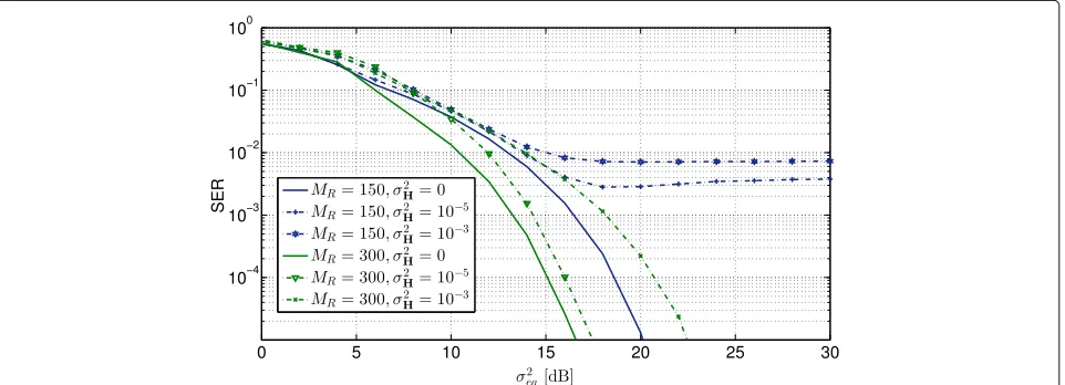
gen-erated from a complex Gaussian distributionCN(0,σH2), with the variance σH2 accounting for the power of the estimation error. Figure 9 depicts the average SER perfor-mance for different values of the equivalent noise, differ-ent numbers of antennas and differdiffer-ent estimation error power.
Imperfect estimation of the channel matrices is still a major drawback in the proposed CF protocol with massive MIMO. ForMR = 150 antennas (blue curves in Fig. 9), when the relay does not exactly know the channel matri-ces, the SER curves forσH2 = 10−5 and forσH2 = 10−3 lead to an error floor. This is caused not only by the noise enhancement caused by ZF filtering but also by the fact
Fig. 9SER curves of the CF massive MIMO protocol for different numbers of relay receiving antennasMR, different interference power levelsσeq2 and
thatDAandDBwill no longer be diagonal (i.e., a unitary
network code is never achieved) changing the geometry of the lattice to a non-orthogonal one, which cannot be handled by the CF scheme.
When a larger number of antennas is considered, as the green curves in Fig. 9 show forMR = 300, and for the same power of the channel estimation error, the error floor disappears (for the depicted SER values) due to the channel hardening effect of large dimensional Gaussian matrices. Nevertheless, these SER curves will eventually stall at an error floor for lower values of SER.
One should note that when increasing the number of antennasMRto a few hundreds antennas, the SER floor decreases to the desired typical values in wireless links (≈10−3), before error correction takes place.
5.2 The three-users case: the Y-network
The two configurations evaluated in the paper for the Y-network were always simulated with LRA with OSIC-MMSE detection at the relay and also at the terminals (in the MIMO detection stage that exists in configuration B). Alternatively, joint ML detection (i.e., “brute force”) is adopted in configuration A when estimating the two final remaining messages. Figures 10 and 11 respectively show the performance results in terms of the overall SER for 4-QAM and 16-4-QAM, using the same constellations in both the uplink and downlink phases, and using the same inter-ference factorsKused in [33]:K=10−3, 10−2, 0.5×10⁻² and 10−1 . Note that both schemes achieve the goal of spending just one time slot per each messages exchange between terminals (with 16-QAM allowing for a more spectrally efficient system). In Fig. 11, one can observe that configuration A, in which a joint ML detection of two (remaining) different messages takes place with only one antenna, exhibits a rather poor performance when using 16-QAM. This is a consequence of a very small Euclidean distance between the symbols resulting from the two received remaining messages after the terminal suppresses its own message; for example, in the case of the detection at terminal 1, the joint ML decision is applied to the sumh2x2+h3x3. Hence, configuration A can only be used for binary or quaternary modulations.
The results in Figs. 10 and 11 quantify how much iso-lation for IBFD communication is required in order to attain a certain targeted performance. As expected, from (10), one can observe in both figures that for a higher interference factorK, the performance deteriorates in all cases. In Fig. 10, one can see that for SNR=35 dB con-figuration B attains SER = 10−3, a typical objective for uncoded wireless transmission. Even in the case of the simpler configuration A, an SNR > 30 dB guarantees a SER below 10−2. Figure 10 shows that the performance is quite similar forK = 10−2orK = 10−3; in other words, for applications that do not usually operate at high SNR,
(a)
(b)
Fig. 10Performances of the two configurations in the Y-network with 4-QAM in both phases. Symbol error rates at the relay (uplink) and at each of the terminals (uplink followed by downlink).aConfiguration A.bConfiguration B
one only needs to optimize the LI isolation up to a cer-tain point, allowing a simpler and cheaper concatenation of isolation and LI cancellation methods. Interestingly, the performance in the low SNR regime does not depend much on the interference term, because thermal noise is the dominant term in that regime.
(a)
(b)
Fig. 11Performances of the two configurations in the Y-network with 16-QAM in both phases. Symbol error rates at the relay (uplink) and at each of the terminals (uplink followed by downlink).aConfiguration A.bConfiguration B
Note that the performance in the uplink phase is the same for both configurations, given that the MAC phase involves the same virtual-MIMO channel in both config-urations. Another observation in both Figs. 10 and 11 is that the performance of the downlink phase is worse than the uplink phase, due to the fact that the former bears the cumulative errors that occur in both the uplink (MAC) and the downlink (broadcast) phases—cf. (14).
6 Conclusions
The paper argues that the immense progress that the physical layer of wireless communications has faced in the last decade offers fruitful opportunities to redesign the protocols in the layers above. This paper has shown that the coexistence of MIMO and massive MIMO, IBFD, and
PLNC allows to greatly reduce the number of orthogonal channels that are needed to exchange messages in relay-centered networks, which translate to the use of many fewer time slots to accomplish message exchanges. Both in the case of the TWRC and the case of the Y-network, it is feasible to asymptotically exchange information between all users using only one time slot on average, instead of the traditional four and six time slots spent in the tradi-tional TDMA approach, respectively, for the TWRC and the Y-network.
In the case of the TWRC, the benefits of having a massive MIMO array allows to use a simple lattice-based PLNC to establish the bidirectional information flow. Massive MIMO not only plays a central role in reducing the inherent interference between the two data flows but also helps overcoming the self-interference at the relay when the number of receiving antennas at the relay increases to a few hundreds. The latter effect was observed via SER curves using typical power levels for the residual self-interference that appear when using state-of-the-art cancellation techniques. Finally, the impact of imperfect CSI (both of the primary links and the loopback interference links) has also been analyzed. The system’s performance is shown to be chiefly dependent on the number of antennas at the relay and also on the channel state information of all the channels involved. For relays with a few hundred antennas, the proposed scheme with only one time slot per message exchange is feasible.
In the case of the Y-network, by assessing the per-formance of the proposed setups for typical levels of residual interference, it was shown that, for good levels of interference cancellation, interference can in fact be well tolerated while allowing doubling the time efficiently of the message exchange mechanism, even when using conventional MIMO in both terminals and also at the relay, while running standard detection algorithms such as LRA detection. For typical values of LI, a sufficient uncoded performance is still achievable at the terminals. In fact, for the more demanding 16-QAM modulation, having two receive antennas at the terminals is manda-tory, such that the MIMO detection diversity of order two allows to separate the two remaining data streams after the initial phase when the terminal cancels its own data.
the assessment of OFDM, given that this is a modula-tion designed to cope with wide-band frequency selective channels and used in the recent versions of the 802.11 family of standards, as well as in 4G celular systems. Another very recent technology that is presently at an early stage of research is power-domain non-orthogonal multiple access (NOMA) [42–45], and the exploration of NOMA with MIMO-IBFD is a major research problem that needs to be addressed. Moreover, as PLNC can be seen as akin to the NOMA concept, a fruitful interplay between these two techniques can be expected.
Acknowledgements
This work was funded by FCT (Foundation for Science and Technology) under project UID/EEA/50008/2013. Francisco A. Monteiro is also grateful to the European COST Action IC1104 – “Random Network Coding and Designs over GF(q)” for having provided funding for learning opportunities in the field of network coding.
Competing interests
The authors declare that they have no competing interests.
Author details
1Instituto de Telecomunicações, Lisbon, Portugal.2Instituto Superior Técnico,
Universidade de Lisboa, Lisbon, Portugal.3ISCTE—Instituto Universitário de
Lisboa, Lisbon, Portugal.
Received: 17 August 2016 Accepted: 24 February 2017
References
1. G Zheng, I Krikidis, C Masouros, S Timotheou, DA Toumpakaris, Z Ding, Rethinking the role of interference in wireless networks. IEEE Commun. Mag.52(11), 152–158 (2014)
2. G Liu, FR Yu, H Ji, VCM Leung, X Li, In-band “full-duplex” relaying: a survey, research issues and challenges. IEEE Commun. Surv. Tutor.17(2), 500–524 (2015)
3. D Kim, H Lee, D Hong, A survey of in-band “full-duplex” transmission: from the perspective of PHY and MAC layers. IEEE Commun. Surv. Tutor.17(4), 2017–2046 (2015)
4. HQ Ngo, HA Suraweera, M Matthaiou, EG Larsson, Multipair “full-duplex” relaying with massive arrays and linear processing. IEEE J. Sel. Areas Commun.32(9), 1721–1737 (2014)
5. JS Lemos, FA Monteiro, I Sousa, A Rodrigues, in2015 IEEE Global Conference on Signal and Information Processing (GlobalSIP). Full-duplex relaying in MIMO-OFDM frequency-selective channels with optimal adaptive filtering (Orlando, 2015), pp. 1081–1085
6. F Boccardi, RW Heath, A Lozano, TL Marzetta, P Popovski, Five disruptive technology directions for 5G. IEEE Commun. Mag.52(5), 74–80 (2014) 7. B Roman, I Wassell, I Chatzigeorgiou, Scalable cross-layer wireless access
control using multi-carrier burst contention. IEEE J. Sel. Areas Commun.
29, 113–128 (2011)
8. RH Louie, Y Li, B Vucetic, Practical physical layer network coding for two-way relay channels: performance analysis and comparison. IEEE Trans. Wirel. Commun.9(2), 764–777 (2010)
9. N Lee, JB Lim, J Chun, Degrees of freedom of the MIMO Y channel: signal space alignment for network coding. IEEE Trans. Inf. Theory.56(7), 3332–3342 (2010)
10. A Chaaban, K Ochs, A Sezgin, in2013 IEEE International Symposium on Information Theory. The degrees of freedom of the MIMO Y-channel (Istanbul, 2013), pp. 1581–1585
11. FS Brás, FE Ferreira, FA Monteiro, A Rodrigues, in2014 IEEE Workshop on Signal Processing Systems (SiPS). Interference suppression with
physical-layer network coding and MIMO for multi-way channels (Belfast, 2014), pp. 1–6
12. FE Ferreira, FA Monteiro, I Sousa, in2016 18th Mediterranean
Electrotechnical Conference (MELECON). Full-duplex MIMO and PLNC for the Y-network (Limassol, 2016), pp. 1–5
13. M Duarte, A Sabharwal, inConference Record of the 44th Asilomar Conference on Signals, Systems and Computers (ASILOMAR). Full-Duplex Wireless Communications Using Off-the-Shelf Radios: Feasibility and First Results (Pacific Grove, 2010), pp. 1558–1562
14. S Hong, J Brand, JI Choi, M Jain, J Mehlman, S Katti, P Levis, Applications of self-interference cancelation in 5G and beyond. IEEE Commun. Mag.
52(2), 114–121 (2014)
15. D Bharadia, McE Milin, S Katti, inProceedings of the 2013 ACM SIGCOMM conference. SIGCOMM ‘13. Full Duplex Radios (Hong Kong, 2013), pp. 375–386
16. M Jain, JI Choi, T Kim, D Bharadia, S Seth, K Srinivasan, P Levis, S Katti, P Sinha, inProceedings of the 17th Annual International Conference on Mobile Computing and Networking. Practical, Real-time, Full Duplex Wireless MobiCom ‘11 (Las Vegas, 2011), pp. 301–312
17. F Rusek, D Persson, BK Lau, EG Larsson, TL Marzetta, O Edfors, F Tufvesson, Scaling up MIMO: opportunities and challenges with very large arrays. IEEE Signal Process. Mag.30, 40–60 (2013)
18. B Nazer, M Gastpar, Reliable physical layer network coding. Proc. IEEE.
99(3), 438–460 (2011)
19. P Popovski, H Yomo, in2007 IEEE International Conference on Communications. Physical Network Coding in Two-Way Wireless Relay Channels (Glasgow, 2007), pp. 707–712
20. R Ahlswede, N Cai, SY Li, R Yeung, Network Information Flow. IEEE Trans. Inf. Theory.46(4), 1204–1216 (2000)
21. S Zhang, SC Liew, PP Lam, inProceedings of the 12th Annual International Conference on Mobile Computing and Networking. Hot Topic: Physical-Layer Network Coding, MobiCom ‘06 (Los Angeles, 2006), pp. 358–365 22. P Popovski, H Yomo, inIEEE International Conference on Communications
(ICC). The Anti-Packets Can Increase the Achievable Throughput of a Wireless Multi-Hop Network, Volume 9 (Istanbul, 2006), pp. 3885–3890 23. B Nazer, M Gastpar, inIEEE International Symposium on Information Theory
(ISIT). Computing over Multiple-Access Channels with Connections to Wireless Network Coding (Seattle, 2006), pp. 1354–1358
24. R Chang, SJ Lin, WH Chung, Symbol and bit mapping optimization for physical-layer network coding with pulse amplitude modulation. IEEE Trans. Wirel. Commun.12(8), 3956–3967 (2013)
25. M Wilson, K Narayanan, H Pfister, A Sprintson, Joint physical layer coding and network coding for bidirectional relaying. IEEE Trans. Inf. Theory.
56(11), 5641–5654 (2010)
26. B Nazer, M Gastpar, Compute-and-forward: harnessing interference through structured codes. IEEE Trans. Inf. Theory.57(10), 6463–6486 (2011) 27. C Feng, D Silva, FR Kschischang, An algebraic approach to physical-layer
network coding. IEEE Trans. Inf. Theory.59(11), 7576–7596 (2013) 28. B Yin, M Wu, C Studer, J Cavallaro, J Lilleberg, inConference Record of the
47th Asilomar Conference on Signals, Systems and Computers (ASILOMAR). Full-Duplex in Large-Scale Wireless Systems (Pacific Grove, 2013), pp. 1623–1627
29. T Riihonen, Vehkapera M, R Wichman, in47th Annual Conference on Information Sciences and Systems (CISS). Large-System Analysis of Rate Regions in Bidirectional Full-Fuplex MIMO Link: Suppression versus Cancellation (Baltimore, 2013), pp. 1–6
30. T Riihonen, S Werner, R Wichman, inConference Record of the 43th Asilomar Conference on Signals, Systems and Computers (ASILOMAR). Spatial Loop Interference Suppression in Full-Duplex MIMO Relays (Pacific Grove, 2009), pp. 1508–1512
31. W Zhang, X Ma, B Gestner, DV Anderson, in45th Annual Conference on Information Sciences and Systems (CISS). Designing Low-Complexity Equalizers for Wireless Systems (Baltimore, 2011), pp. 1–6 32. G Zheng, Joint beamforming optimization and power control for
“full-duplex” MIMO two-way relay channel. IEEE Trans. Signal Process.
63(3), 555–566 (2015)
33. S Tedik, GK Kurt, in2014 IEEE 79th Vehicular Technology Conference (VTC Spring). Practical Full Duplex Physical Layer Network Coding (Seoul, 2014), pp. 1–4
34. Y Sun, Y Yang, P Si, R Yang, Y Zhang, Novel self-interference suppression schemes based on Dempster-Shafer theory with network coding in two-way “full-duplex” MIMO relay. EURASIP J. Wirel. Commun. Netw.
2016(109), 1–16 (2016)
36. Y Wu, PA Chou, SY Kung, inConf. on Information Sciences and Systems (CISS). Information exchange in wireless networks with network coding and physical-layer broadcast (Princeton, 2005)
37. R Zamir,Lattice Coding for Signals and Networks. (Cambridge University Press, Cambrige, 2014)
38. A Chockalingam, S Rajan,Large MIMO Systems. (Cambridge University Press, Cambrige, 2014)
39. A Sabharwal, P Schniter, D Guo, DW Bliss, S Rangarajan, R Wichman, In-band “full-duplex” wireless: challenges and opportunities. IEEE J. Sel. Areas Commun.32(9), 1637–1652 (2014)
40. JS Lemos, F Rosário, FA Monteiro, J Xavier, A Rodrigues, inIEEE 16th International Workshop on Signal Processing Advances in Wireless Communications (SPAWC). Massive MIMO “full-duplex” relaying with optimal power allocation for independent multipairs (Stockholm, 2015), pp. 306–310
41. FA Monteiro, I Wassell, N Souto,MIMO Detection Methods. MIMO Processing for 4G and Beyond: Fundamentals and Evolution, chap. 2. (CRC Press, Boca Raton, 2014), pp. 47–117
42. SMR Islam, N Avazov, OA Dobre, KS Kwak, Power-Domain
Non-Orthogonal Multiple Access (NOMA) in 5G Systems: Potentials and Challenges (2017). http://ieeexplore.ieee.org/document/7676258/ 43. Z Ding, Y Liu, J Choi, Q Sun, M Elkashlan, I CL, HV Poor, Application of
non-orthogonal multiple access in LTE and 5G Networks. IEEE Commun. Mag.55(2), 185–191 (2017)
44. S Liu, C Zhang, Non-orthogonal multiple access in a downlink multiuser beamforming system with limited CSI feedback. EURASIP J. Wirel. Commun. Netw.2016, 239 (2016)
45. X Su, H Yu, W Kim, C Choi, D Choi, Interference cancellation for non-orthogonal multiple access used in future wireless mobile networks. EURASIP J. Wirel. Commun. Netw.2016, 231 (2016)
46. T Riihonen, X Wang, inRelaying in “full-duplex” radio communication systems. Institution of Engineering and Technology (IET), (London 2016), pp. 129–173. Advanced Relay Technologies in Next Generation Wireless Communications, chap. 5
47. H Krishnaswamy, G Zussman, 1 Chip 2x the bandwidth. IEEE Spectrum.
53(7), 38–54 (2016)
48. Z Zhang, X Chai, K Long, A Vasilakos, L Hanzo, Full duplex techniques for 5G Networks: self-interference cancellation, protocol design, and relay selection. IEEE Commun. Mag.53(5), 128–137 (2015)
49. ME Knox, inIEEE 13th Annual Wireless and Microwave Technology Conference (WAMICON). Single Antenna Full Duplex Communications using a Common Carrier (Cocoa Beach, 2012), pp. pp. 1–6
50. M Heino, D Korpi, T Huusari, Antonio-E Rodriguez, S Venkatasubramanian, T Riihonen, L Anttila, C Icheln, K Haneda, R Wichman, M Valkama, Recent advances in antenna design and interference cancellation algorithms for in-band full duplex relays. IEEE Commun. Mag.53(5), 91–101 (2015) 51. I Krikidis, HA Suraweera, Full-duplex cooperative diversity with alamouti
space-time code. IEEE Wirel. Commun. Lett.2(5), 519–522 (2013) 52. HA Suraweera, I Krikidis, G Zheng, C Yuen, PJ Smith, Low-complexity
end-to-end performance optimization in MIMO “full-duplex” relay system. IEEE Trans. Wirel. Commun.13(2), 913–926 (2014)
53. M Duarte,Full-duplex Wireless: Design, Implementation and Characterization. PhD thesis, Rice University, 2012
54. H Alves, da DB Costa, RD Souza, M Latva-aho, inIEEE 14th Workshop on Signal Processing Advances in Wireless Communications (SPAWC). On the performance of two-way half-duplex and one-way “full-duplex” relaying (Darmstadt, 2013), pp. 56–60
55. P Lioliou, M Viberg, M Coldrey, F Athley, in44th Asilomar Conference on Signals, Systems and Computers (ASILOMAR). Self-Interference Suppression in Full-Duplex MIMO Relays (Pacific Grove, 2010), pp. 658–662
56. E Antonio-Rodriguez, R Lopez-Valcarce, T Riihonen, S Werner, R Wichman, inIEEE 14th Workshop on Signal Processing Advances in Wireless
Communications (SPAWC). Adaptive Self-Interference Cancellation in Wideband Full-Duplex Decode-and-Forward MIMO Relays (Darmstadt, 2013), pp. 370–374
57. F Rosário, FA Monteiro, A Rodrigues, Fast matrix inversion updates for massive MIMO detection and precoding. IEEE Signal Process. Lett.23, 75–79 (2016)
58. DC Araújo, T Maksymyuk, ALF de Almeida, T Maciel, JCM Mota, M Jo, Massive MIMO: survey and future research topics. IET Commun.10(15), 1938–1946 (2016)
59. U Madhow, D Brown, S Dasgupta, R Mudumbai, inInformation Theory and Applications Workshop (ITA), 2014. Distributed Massive MIMO: Algorithms, Architectures and Concept Systems (San Diego, 2014), pp. 1–7 60. HA Suraweera, HQ Ngo, T Duong, C Yuen, E Larsson, inIEEE International
Conference on Communications (ICC). Multi-Pair Amplify-and-Forward Relaying with Very Large Antenna Arrays (Budapest, 2013), pp. 4635–4640 61. TVT Le, YH Kim, Power and spectral efficiency of multi-pair massive
antenna relaying systems with zero-forcing relay beamforming. IEEE Commun. Lett.19(2), 243–246 (2015)
62. R Wyrembelski, T Oechtering, H Boche, inIEEE 19th International Symposium on Personal, Indoor and Mobile Radio Communications (PIMRC). Decode-and-Forward Strategies for Bidirectional Relaying (Cannes, 2008), pp. 1–6
63. T Koike-Akino, P Popovski, V Tarokh, Optimized constellations for two-way wireless relaying with physical network coding. IEEE J. Sel. Areas Commun.27(5), 773–787 (2009)
64. J Zhan, B Nazer, M Gastpar, U Erez, inIEEE International Symposium on Information Theory (ISIT). MIMO Compute-and-Forward (Seoul, 2009), pp. 2848–2852
65. MM Molu, K Cumanan, A Burr, Low-complexity compute-and-forward techniques for multisource multirelay betworks. IEEE Commun. Lett.
20(5), 926–929 (2016)
Submit your manuscript to a
journal and benefi t from:
7Convenient online submission 7Rigorous peer review
7Immediate publication on acceptance 7Open access: articles freely available online 7High visibility within the fi eld
7Retaining the copyright to your article