Scholarship@Western
Scholarship@Western
Electronic Thesis and Dissertation Repository
9-29-2014 12:00 AM
Characterization of a Contact-Stylus Surface Digitization Method
Characterization of a Contact-Stylus Surface Digitization Method
Using Collaborative Robots: Accuracy Evaluation in the Context of
Using Collaborative Robots: Accuracy Evaluation in the Context of
Shoulder Replacement or Resurfacing
Shoulder Replacement or Resurfacing
Sara Saud Zimmo
The University of Western Ontario
Supervisor Dr. Louis Ferreira
The University of Western Ontario
Graduate Program in Biomedical Engineering
A thesis submitted in partial fulfillment of the requirements for the degree in Master of Engineering Science
© Sara Saud Zimmo 2014
Follow this and additional works at: https://ir.lib.uwo.ca/etd
Part of the Biomechanics and Biotransport Commons, Biomedical Commons, and the Other Biomedical Engineering and Bioengineering Commons
Recommended Citation Recommended Citation
Zimmo, Sara Saud, "Characterization of a Contact-Stylus Surface Digitization Method Using Collaborative Robots: Accuracy Evaluation in the Context of Shoulder Replacement or Resurfacing" (2014). Electronic Thesis and Dissertation Repository. 2471.
https://ir.lib.uwo.ca/etd/2471
This Dissertation/Thesis is brought to you for free and open access by Scholarship@Western. It has been accepted for inclusion in Electronic Thesis and Dissertation Repository by an authorized administrator of
Resurfacing
Thesis format: Integrated Article
by
Sara S. Zimmo
Graduate Program in Biomedical Engineering
A thesis submitted in partial fulfillment of the requirements for the degree of
Master of Engineering Science
The School of Graduate and Postdoctoral Studies The University of Western Ontario
London, Ontario, Canada
ii
Abstract
Total shoulder arthroplasty (TSA) is the third most common joint replacement. While
robot-assisted hip and knee replacement technologies have enjoyed extensive development, this has
been limited in the upper limb. This work focused on quantifying the localization accuracy of
a robotic system, and evaluating its efficacy in the context of TSA.
A collaborative robot was fitted with a stylus tip to perform manual surface digitizations
using the robot’s encoder output. In the first experiment, two precision-machined master
cubes, representing the working volume around a glenoid structure, were used for system
validation. Next, cadaveric glenoids were digitized and compared to a ‘gold standard’ laser
scanner. Digitization errors were 0.37±0.27 mm, showing that collaborative robotics can be
used for osseous anatomy digitization.
This thesis presents two novel concepts: 1) use of collaborative robotics for manually
operated surface digitizing, and 2) optical fiducial technique, allowing registration between a
laser scanner and stylus digitizer.
Keywords
Registration, Digitization, Robot-Assisted, Collaborative Robot, Glenoid, Total Shoulder
iii
Acknowledgments
The completion of this thesis would not have been made possible without the support and
contribution of many individuals.
Firstly, I thank my supervisor, Dr. Louis Ferreira for his guidance, advice and endless words
of wisdom. I am fortunate for his patience and mentoring skills, which aided in my
development and success as a graduate student. Louis’s care for my work and growth
provided me with opportunities to attend several talks and conferences. I also greatly
appreciate his creative and insightful ideas – may he never stop creating awesome ideas.
Many thanks to Dr. Emily Lalone, who helped me with the registration process for my thesis.
She was motivational, helpful, and very encouraging. She always created a very exciting
environment to work in! To Nikolas Knowles, you made my time in the lab easier and
enjoyable, and with your awesome advice and suggestions made my life easier. Thank you!
I would also like to thank Clayton Cook and Chris Vandelaar from the University Machine
Services for taking their time to discuss our ideas and continued revisions for best value and
result. Also, I appreciate the time we had together, it was never a dull moment! Thank you
Chris, I learned a lot from you, especially on how to minimize cost, which was beneficial!
To the staff at the Writing Support Centre, thank you for proofreading my thesis and
improving my writing skills. I definitely recommend everyone to go there!
Thanks to Maryam Mohammad who drew a few of the pictures included in my thesis to ease
the work for me. They were pretty awesome. To Fatima Ba’abbad who saved me in the last
minute wanting to help, thank you!
A special thank you to my best friend, Hana Dakkak, whose support from the start helped me
keep going. She is truly someone I can rely on for advice, ideas, and to always put a smile on
my face. To Amir Hage, I express great gratitude for your positive attitude and great
proofreading skills. Your eagerness to always help is truly inspiring and motivational.
Lastly, my deepest appreciation to my family and especially my parents. To my siblings,
iv
thanks to my oldest sister Sahar who has been my biggest role model and strongest advocate.
To my parents, Saud Zimmo and Fatima Chahbar, thanks for going through every hardship
just to get me through. Thanks for your patience and continuous support and encouragement
v
Table of Contents
Abstract ... ii
Acknowledgments... iii
Table of Contents ... v
List of Tables ... vii
List of Figures ... viii
List of Appendices ... x
1 Introduction ... 1
1.1 Shoulder Anatomy, disease and joint replacement ... 1
1.1.1 Anatomy and Function ... 1
1.1.2 Shoulder Conditions... 7
1.1.3 Total Shoulder Replacement ... 7
1.2 Robotic joint replacement or resurfacing in other joints ... 18
1.3 Robots ... 21
1.3.1 Definition ... 21
1.3.2 Surgical Robot ... 23
1.3.3 Advantages and Disadvantages ... 25
1.3.4 Safety Considerations ... 26
1.4 Registration and Digitization ... 27
1.4.1 Digitization Device ... 28
1.4.2 Advantages and Disadvantages of Digitizing Technologies ... 33
1.4.3 Accuracy Assessments ... 34
1.5 Rationale ... 38
1.6 Objective ... 39
vi
1.8 Thesis Overview ... 39
1.9 References ... 40
2 Determination of the accuracy of a 7-axis collaborative robot as a manually operated surface digitizer: with emphasis on robot-assisted surgeries within small working volumes ... 48
2.1 Introduction ... 48
2.2 Methods... 49
2.3 Results ... 61
2.4 Discussion ... 66
2.5 References ... 70
3 Evaluation of a 7-Axis Collaborative Robot as a Bone Surface Digitizer: With Validation in an In-Vitro Glenoid Model ... 72
3.1 Introduction ... 72
3.2 Methods... 73
3.3 Results ... 77
3.4 Discussion ... 83
3.5 References ... 86
4 Conclusion and Future Directions ... 89
4.1 Conclusions ... 89
4.2 Future Directions ... 90
Appendices ... 93
vii
List of Tables
Table 1.1: Advantages and Disadvantages of Digitization Devices ... 33
Table 2.1: Location of the Digitized Area ... 59
Table 2.2: Summary of Error Metrics for Both Digitization Blocks ... 66
Table 3.1: Summarized Error Results of each Specimen for each Method ... 82
Table A.1: Side-by-side Comparison Between Each Technique ... 99
Table B.1: Description of all Specimens ... 100
Table C.1: Basic Data ... 101
Table C.2: Ambient Temperature and Conditions ... 101
Table C.3: Axis Data... 102
Table C.4: Mounting Flange ... 105
Table C.5: Type of Loads Acting on the Mounting Base ... 108
Table C.6: Cartesian Stiffness Controller: Parameterization ... 108
viii
List of Figures
Figure 1.1: The Osseous Anatomy of a Shoulder ... 2
Figure 1.2: Four Different Joints in the Shoulder ... 4
Figure 1.3: The True Shoulder Joint – Glenohumeral Joint ... 5
Figure 1.4: A Drawing of Glenoid Fossa ... 6
Figure 1.5: Anatomic Parameters ... 10
Figure 1.6: Two Types of Glenoid Component: Pegged and Keeled ... 14
Figure 1.7: Glenohumeral Implant Conformity ... 16
Figure 1.8: The Robodoc System... 19
Figure 1.9: Representation of Revolute and Prismatic Joints ... 22
Figure 1.10: Electromagnetic Tracking System: Polhemus Patriot Digitizer ... 29
Figure 1.11: Optical Tracking System: Optotrak Certus ... 31
Figure 1.12: Mechanical Arm Digitizers: Microscribe 3DX and FARO Arm ... 32
Figure 1.13: Overview of ISO 5725-1:1994 ... 35
Figure 1.14: Accuracy Assessment Block ... 37
Figure 2.1: Stylus Handle of the Robot ... 51
Figure 2.2: Rounded-tip Calibration Error... 52
Figure 2.3: An Isometric View of Block B1 ... 54
Figure 2.4 a-f: Block B2 with Six Different Layers at 10 mm Displacement ... 55
ix
Figure 2.6: The KUKA LWR 4+ Digitization on the Block Mounted onto the Tower Jig. ... 58
Figure 2.7: Volume Digitization Error of Block B1 ... 62
Figure 2.8: Volume Digitization Error of Block B2 ... 63
Figure 2.9: Perimeter Digitization Error of Block B1 ... 64
Figure 2.10: Perimeter Digitization Error of Block B2 ... 65
Figure 3.1: Glenoid Acrylic Base Set Up ... 74
Figure 3.2: An Illustration of the Spatial Calculation to Determine the Fiducial Marker ... 76
Figure 3.3: Fiducial Registration Error using Paired Point Registration ... 79
Figure 3.4: The Residual Error between Laser Scan and Robot Digitization ... 80
Figure 3.5: Proximity Maps of Residual Distance Error ... 81
Figure A.1: Different Elbow Configuration of the Robot... 95
Figure A.2: A Side View of the Robot with Different Elbow Configuration ... 96
Figure A.3: A Side View of the Robot Stylus Rotating at a Fixed Point ... 97
Figure A.4: Determination of the Variability in the Hemi-Sphere ... 98
Figure C.1: Robot Axes ... 103
Figure C.2: Working Envelope ... 104
Figure C.3: Mounting Flange ... 106
x
List of Appendices
Appendix A: Location Measurement Variability as a Function of Robot Joint Configuration
... 93
Appendix B: Specimen Information ... 100
Appendix C: Robot Specification Data Sheet ... 101
Chapter 1
1
Introduction
1.1 Shoulder Anatomy, disease and joint replacement
The upper extremities of the human body allow interaction with surrounding
environments. Specifically, the shoulder joint provides the most mobility within the
whole body, and is capable of performing a variety of movements.
1.1.1
Anatomy and Function
The anatomy of a shoulder allows more movement than any other joint in the body. A
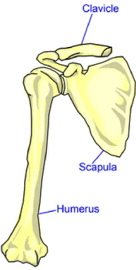
shoulder is made up of three bones: the humerus, scapula and clavicle, as shown in
Figure 1.1 (1, 2).
A humerus, or upper arm bone, is a long bone in the upper limb, with a humeral head on
the proximal end shaped like a ball. The humerus allows the movement and functionality
of the arm as it is a link from the elbow to the shoulder. A scapula is a shoulder blade
shaped in a thin, triangular bone, concaved anteriorly on the back of the upper rib. The
scapula connects the humerus with the clavicle as a floating link to allow a larger range
of motion. The clavicle is also known as the collarbone, and is a long curvy bone that
Figure 1.1: The Osseous Anatomy of a Shoulder
Illustrated is an anterior view of the right shoulder; the shoulder consists of three bones:
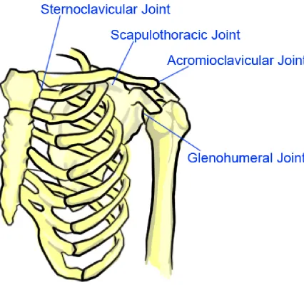
Contrary to popular belief, the four joints that make up a shoulder joint are: the
glenohumeral joint (GHJ), acromioclavicular joint (ACJ), sternoclavicular joint (SCJ)
and scapulothoracic joint (STJ) (Figure 1.2). The ACJ is where the clavicle meets the
acromion, a bony process on the posterior and superior side of the scapula. It is the only
articulation between the clavicle and scapula, providing extra flexibility in the shoulder
joint as it allows the ability to raise the arm above the head. The SCJ controls the axial
skeleton on the front of the chest and the upper extremity. The STJ is formed where the
scapula glides against the thorax, more commonly known as the rib cage. This joint is
usually not defined in many sources, as it is not a true anatomic joint with no
bone-on-bone motion, but it is an articulation and it keeps the glenoid lined up during shoulder
movements. (3-5).
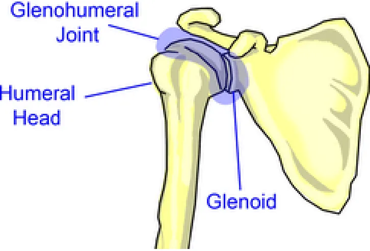
The main or true shoulder joint is the GHJ shown in Figure 1.3. The GHJ is a ball and
socket joint formed by a glenoid and the head of the humerus (1-3). The glenoid fossa or
cavity is a depression on the head of the scapula; it is also the shallow socket for the
humerus ball to rotate in making the GHJ (Figure 1.4). The surface of a glenoid and
humerus is an articular cartilage, which is a smooth substance that allows the bones to
move easily, as well as protects the bones. The GHJ has a frictionless motion due to the
synovial membrane, a small, thin tissue that creates a fluid to lubricate the cartilage to
eliminate friction. Therefore, the GHJ is mostly unconstrained and, like a golf tee, is not
very conforming; it is surrounded by a rim called the glenoid labrum and relies on
soft-tissue and muscle support.
The rotator cuff is a network of muscles and tendons surrounding the shoulder to provide
stability, support, and the ability to move the bones around (2). The rotator cuff surrounds
the head of the humerus, attaches the humerus to the scapula, and keeps the arm in the
glenoid (6). Ideally, the GHJ consists of three degrees-of-freedom (DOF):
supination/pronation (yaw), flexion/extension (roll), and abduction/adduction (pitch).
However, the GHJ is not purely a rotational DOF, as the GHJ consists of rotational and
minimal translational movements (7), especially in any injury or pathology that may have
Figure 1.2: Four Different Joints in the Shoulder
The anterior view of the left shoulder is portrayed. The sternoclavicular joint, the
scapulothoracic joint, the acromioclavicular joint and the glenohumeral joint are four
Figure 1.3: The True Shoulder Joint – Glenohumeral Joint
An anterior view of the right glenohumeral joint (GHJ) is depicted. The GHJ is most
commonly known shoulder joint, and consists of the head of the humerus and the glenoid.
Figure 1.4: A Drawing of Glenoid Fossa
The glenoid fossa, or glenoid, is located at the lateral angle of the scapula. Glenoid is
shaped as a socket for the humeral head, and has rim around the edge to contain the
1.1.2
Shoulder Conditions
Several conditions in the shoulder may lead to shoulder arthroplasty, such as
osteoarthritis, rheumatoid arthritis and rotator cuff tear arthropathy.
Osteoarthritis, known as “wear and tear” arthritis, is a degenerative joint disease in which
the cartilage on the joint deteriorates. Osteoarthritis has two types: primary, which is
idiopathic, and secondary caused by another condition such as an injury. In shoulder
osteoarthritis, the cartilage on the humeral head and glenoid are worn, reducing the
cushioning effect in the joint. As a result, the surfaces of the humeral head and the
glenoid become rough, and thus the bones become exposed. Consequently, patients may
experience pain and stiffness in the shoulder as the bones rub and grate against each
other, limiting their physical activities, work time and functionality of the shoulder (10).
Rheumatoid arthritis is a chronic inflammatory autoimmune disease, a systematic disease
that attacks specific components of the body. The synovial membrane that surrounds the
joint becomes inflamed and thickened, which can cause cartilage and bone destruction in
the joints. This results in severe pain and disability due to joint deformity.
Patients with rotator cuff tear arthropathy have had a rotator cuff tear for a long time,
eventually causing them to have shoulder joint disease. A rotator cuff tear involves one or
more torn tendons in the rotator cuff, and a humerus head that is not attached fully to the
rotator cuff. If there is no early diagnosis or treatment, this can lead to arthropathy, which
can result in arthritis and destruction of the joint cartilage (2, 6).
Treatments for these conditions involve medication, physiotherapy, and surgery. When
the medication and physiotherapy do not improve the functionality, surgery is
recommended as a last resort. The most common cause of a total shoulder replacement is
osteoarthritis in the GHJ, as it directly involves the replacement of the cartilage and
bones (2, 11).
1.1.3
Total Shoulder Replacement
The shoulder, after the knees and hip, is the third most common joint requiring surgical
lost due to degenerative joint disease. The first successful shoulder replacement recorded
was performed by Péan in 1882 to treat tuberculosis arthritis using a rubber and platinum
prosthesis (12). Since then, many discoveries about total shoulder arthroplasty (TSA)
have been implemented and are still undergoing research to improve the arthroplasty
design. From the original design, in which the GHJ was replaced with a mechanical joint,
to current total shoulder arthroplasty, in which the damaged head of the humerus is
removed and is replaced by a smooth metal ball with a stem that is press-fitted into the
humerus, studies have shown that the shoulder replacement surgery is still improving. In
this current procedure, the glenoid is resurfaced with a high-density polyethylene
component (13).
TSA is an option for those patients with osteoarthritis in the glenohumeral joint where the
pain is interfering with their everyday activities and sleeping patterns, as well as for those
who have had non-surgical treatments without improvement to their functionality (11).
Although hemiarthroplasty, in which one bone of the joint is replaced, is much easier to
perform due to glenoid complications, TSA is recommended over hemiarthroplasty; in
their study of the treatment of glenohumeral osteoarthritis, Izquierdo et al. (2010) show
that the global health assessment scores and pain relief of the shoulder were statistically
significantly better after TSA (11). The stability and normal load transfer cannot be
restored to a degraded glenoid anatomy if hemiarthroplasty is performed. Furthermore,
compromising the structure or mechanical properties of cartilage of the glenoid will result
in the loss of the normal load-distributing and stabilizing mechanisms of the joint, and the
accelerated wear of the cartilage due to the loss of even distribution of force (14).
TSA is a highly technical procedure (13). In summary, it is performed by making an
incision on the anterior of the shoulder, between two muscles, the deltoid and the
pectoralis major, to access the glenohumeral joint. Once the incision is open, the scar
tissue that restricted the motion of the shoulder is removed, and one of the tendons is cut
to further access the joint. The damaged humeral head is removed, and prepared for a
humeral component placement. A smooth metal ball with a stem is press-fitted into the
humerus. The placement of the glenoid is prepared by reaming, which will shape and
that was cut in the beginning of the procedure is repaired to the bone.
Glenoid complications are the most common challenge in TSA and require extensive
attention to the glenoid component in the surgery. Complications include inadequate
preparation of the bone surface, the prosthesis not fully seated on the prepared bone and
insufficient bone left for glenoid placement (15).
1.1.3.1
Glenoid Component
Many studies show that the glenoid component remains a primary concern in TSA, as
large percentages of failures of shoulder arthroplasties are related to problems in
managing the glenoid socket (15-18). This complication causes post-operative pain and
limited functionality of the shoulder, as well as a potential need for a revision surgery.
1.1.3.1.1
Anatomic Parameters
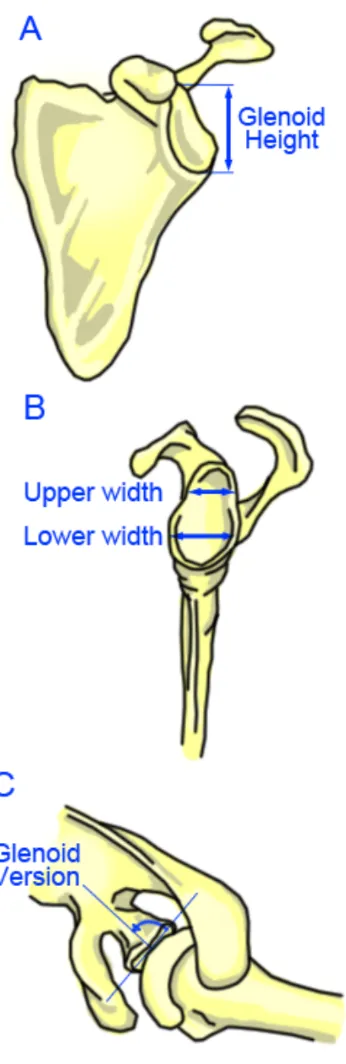
Anatomic parameters are considered to determine the glenoid implant and placement,
including glenoid height, width, inclination, shape and version as shown in Figure 1.5
(18, 19). A normal glenoid cavity has a pear shape (20) or is an elliptical (18). Glenoid
height is defined as the distance between the most superior and inferior points of the
glenoid. Glenoid width is the distance between the most anterior and posterior points on
the glenoid. Glenoid inclination is defined as the slope of the glenoid surface area along
the superior and inferior axis. Glenoid version is defined as the angular orientation of the
axis of the glenoid articular surface relative to the long (transverse) axis of the scapula;
posterior or positive angle is denoted as retroversion, while negative angle is anteversion
(18, 21).
Three evaluations of the glenoid are used to report its anatomic parameters, specifically
the height, weight and version. Checroun et al. (2002) evaluated 412 cadaveric scapulae
(22), Iannotti et al. (1992) evaluated 96 shoulders of patients and 44 cadaveric scapulae;
Iannotti et al. reported that there is no significant difference between the cadaveric
glenoid and those in live patients (20). Lastly Churchill et al. (2001) evaluated 172
matched pairs or 344 cadaveric scapulae; Churchill et al. chose 50 black men, 50 white
Figure 1.5: Anatomic Parameters
(A) Displays the glenoid height (B) Displays the upper and lower width if the glenoid is pear
In terms of glenoid shape, Checroun et al. reported that, of 412 cadaveric glenoid, 71%
were pear shaped, and 29% were elliptical, and found that female glenoids were 10%
smaller than male glenoids. Iannotti et al. only mentioned pear shapes, and reported a
ratio of lower to upper anterior-posterior measurement of 1:0.08 ± 0.01. Churchill et al.
made no mention of the shape of the glenoid.
With regards to glenoid height, Checroun et al. reported a mean glenoid height of
37.9 ± 2.7 mm. Iannotti et al. reported a mean glenoid height of 39 ± 3.7 mm. Churchill
et al. found that although the two races did not vary, there was a significant difference
between gender; Churchill et al. reported a mean male glenoid height of 37.5 ± 2.2 mm
and female glenoid height of 32.6 ± 1.8 mm (p < 0.001).
Concerning glenoid width, Checroun et al. reported a mean glenoid width of
29.3 ± 2.4 mm. Iannotti et al. reported two widths for each glenoid, as he believed the
glenoids were pear-shaped. Thus Iannotti et al. reported a mean upper glenoid width of
23 ± 2.7 mm and a mean lower glenoid width of 29 ± 3.1 mm. Churchill et al. reported a
mean glenoid width of 27.8 ± 1.6 mm in male specimens and 23.6 ± 1.5 mm in female
specimens (p < 0.001).
Only Churchill et al. made mention of glenoid inclination, and found that there was a
variability between gender and race, although not statistically different (p = 0.07 between
black men and white women). He found that the glenoid was superiorly inclined by
4.0 ± 3.4° in male specimens and superiorly inclined by 4.5 ± 3.8° in females.
Regarding glenoid version, Churchill et al. reported a mean glenoid retroversion of
1.23 ± 3.5°. Churchill et al. found no significant difference between gender; however
there is a difference between race as white patients were more retroverted than black
males (mean white, 2.66; mean black, 0.20; p < 0.00001). The parameter of glenoid
version has been emphasized in recent studies, with a normal range varying from 2°
anteversion to 9° retroversion and noted changes in version in the presence of
1.1.3.1.2
Glenoid Pathology
Glenoid arthritis is frequently associated with glenoid wear (18). Walch et al. generated a
classification system to describe glenoid wear patterns in arthritic glenoid after observing
113 GHJ with primary osteoarthritis (23). Walch et al. classified the main glenoid types
as A, B, and C.
Type A is classified as concentric wear, in which the humeral head is centered to allow
equal distribution of the joint reaction force along the glenoid surface. The minor erosion
is classified as Type A1, and the major as Type A2. Walch et al. found that the average
retroversion is 11.5 ± 8.8°. Type B is categorized by a posterior humeral head
subluxation with a posterior glenoid wear pattern; a joint reaction force is distributed
asymmetrically. Retroversion was found to be at least 18 ± 7.2°. Type C is defined by
glenoid retroversion of more than 25°, regardless of erosion.
In primary osteoarthritis, Walch et al. found that Type A was the most used in 1999;
however more recent studies found that Type B, or posterior glenoid wear due to humeral
head subluxation in the posterior joint, was the most common pattern (14, 18, 24). A
good preoperative axillary view is used to determine the glenoid wear, as it shows the
shape of the glenoid, as well as the position of the humerus, to assess for the extent and
location of the glenoid wear (14).
Iannotti et al. (2005) explained that there are two main reasons for glenoid retroversion of
patients with primary osteoarthritis with Type B to lead to posterior instability (25). First,
increasing glenoid retroversion causes the joint reaction force to translate posteriorly,
causing an off-axis moment, and posteriorly directed shear force across the glenoid face.
Second, the retroverted glenoid will effectively decrease the posterior wall height or joint
constraint.
1.1.3.1.3
Glenoid Design and Fixation
The primary goal in TSA is to ensure no complications in the glenoid component,
specifically in the glenoid placement. Therefore, many studies have attempted to
limited to, metal vs. polyethylene backing, in-growth vs. cemented placement, and
pegged vs. keeled.
A study by Fox et al. (2009) collected 1542 primary total shoulder replacements and
presented 20 years follow-up data on a number of glenoid implant designs (26). The two
materials that Fox et al. evaluated were metal-backed, in which the glenoid surface is
polyethylene and the implanted area of the component is metal, and polyethylene, in
which the component is all polyethylene. Fox et al. found that metal-backed glenoid
components have the most surgery revisions due to infection, instability, wear and
loosening relative to polyethylene. The differences between the two materials are large;
2.3% of all metal-backing were infected, compared to 0.6% of all polyethylene; the
instability rate was 3.5% for metal-backed, compared to 0.5% for polyethylene. Overall,
16.7% of the metal-backed required surgery revisions, compared to 2.7% of the
polyethylene. Fox et al. concluded that the material used for the backing was significantly
associated with revisions. Fox et al. also found that the bone in-growth, non-cemented
implants are at a greater risk for failure over time due to material wear, component
loosening and instability compared to cemented implants. Finally, Fox et al. discovered
that aseptic loosening was the most common reason for revision, and contributed to about
42% of all revisions. Fox et al. concluded that to achieve the best survival of the glenoid
component involved using polyethylene and cemented implants.
Throckmorton et al. (2010) conducted a long-term study to determine the failure rate of
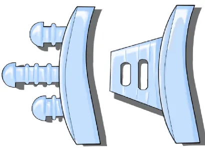
two types of mounting designs, pegged or keeled (27). The design of each component
type is shown in Figure 1.6, where the pegged design has three pegs aligned in the
superior-inferior axis, and the keeled design has a thick and flat trapezoid shape.
Throckmorton et al. compared their findings to two studies; one of these studies reported
that biomechanical analysis suggested pegged components perform better with normal
bone stock, while keeled components performed better with inadequate bone stock. The
other study reported that keeled components were most likely to shift in position and that
Figure 1.6: Two
The glenoid components have two different types to implant into the bone
in the drawing. The left shows a pegged component, and the right shows a keeled
component. Pegged component has three pegs, with small
placement of the implant. The keeled component is shaped as a trapezoid, with holes to
allow cement through to secure placement.
Two Types of Glenoid Component: Pegged and
lenoid components have two different types to implant into the bone
left shows a pegged component, and the right shows a keeled
component. Pegged component has three pegs, with small rims around each
placement of the implant. The keeled component is shaped as a trapezoid, with holes to
secure placement.
egged and Keeled
lenoid components have two different types to implant into the bone, as represented
left shows a pegged component, and the right shows a keeled
rims around each peg to secure
The mean radiographic follow-up period was approximately 4 years, and found no
significant difference between both groups regarding clinical or radiographic
performance. Therefore, to optimize the design, polyethylene cemented design is
favoured, and although there is no significant difference between pegged and keeled
design, some studies prefer a pegged design as it has better seating. However, factors that
limit component fixation include inadequate bone stock and low strength of the available
bone (18); therefore, there is a need for further research in pegged vs. keeled design
regarding the associated limiting factors. It is important to note that nonconcentric
glenoid wear is often treated by eccentrically reaming the glenoid to correct the glenoid
version and improve fixation; instead of compensating the glenoid retroversion with
humeral anteversion, as Iannotti et al. reported that humeral component version does not
affect the glenoid component wall height or joint constraint (25).
Another factor contributing to the glenoid component design is the glenohumeral implant
conformity (Figure 1.7). Glenohumeral implant conformity is the relationship between
the convexity of the humeral head and the concavity of the glenoid components.
Biomechanics of the joint, specifically loading and stability, are significantly influenced
by the conformity of the glenohumeral joint (19). Concavity compression refers to the
stability obtained by compressing the humeral head into the concave glenoid fossa (28).
Increasing the magnitude of the compression load into the glenoid concavity increases the
stabilization of the GHJ, and the distributed loads is evenly spread in the glenoid.
Therefore equal convexity and concavity is desired as the GHJ is conformed; however
due to the compression, GHJ is constraint to humeral translation in the glenoid (14, 19).
Therefore, several studies suggested reaming the glenoid to create a radial mismatch,
which results in a greater glenoid radius than the humeral head radius (29-33).The radial
mismatch decreases the risk of glenoid loosening, as Nho et al. reported that on a
retrieval study, conformed glenoid components have greater wear than non-conformed
glenoid components (33). Therefore, a trade-off is shown between polyethylene wear and
GHJ stability; and as a result, the optimal radial mismatch is 6-7 mm, as discovered by
Figure 1.7: Glenohumeral Implant Conformity
A) Correct way of conforming the glenohumeral joint, as the load applied causes the
reaction force to be distributed evenly along the implant. B) Case when the glenoid is
incorrectly placed, the loading is applied on one side, causing the reaction force to behave
like a rocking horse. This will then loosen the glenoid component as well as accelerate
wear.
1.1.3.1.4
Glenoid Component Failure
Matsen et al. (2008) reported many failures involving glenoid components, including the
failure of the component itself, the component seating, and the prosthetic loading (15).
Failures of the component itself include pitting and erosive wear on the prosthesis
surface, the fracture of the glenoid component including the keel or peg fracture, and
fracture of the polyethylene body. The wear of the glenoid due to metal backing as well
as the separation of the polyethylene and metal are also failures of the component itself.
Failures of the component seating include inadequate preparation of the bone surface, the
prosthesis not fully seated on prepared bone and inadequate bone stock for component
placement. Prostheses not fully seated on the prepared bone, which may be caused by
glenoid component malalignment, is the most common reason to have surgery revisions.
Glenoid component malpositioning contributes to aseptic loosening, as the distributed
force is not applied on the glenoid face evenly, causing one end to elevate as the other
end compresses. Matsen et al. reported a study that showed seating was much worse for
the keeled component than for the pegged component, due to the precision of the match
between the geometry of the design to the prepared bone. Insufficient bone stock is also
an issue as there is no support to secure the fixation of the glenoid component.
Failures due to prosthetic loading include the glenohumeral implant conformity, rim
loading, glenohumeral instability and rotator cuff insufficiency. Glenohumeral implant
conformity can influence failure by the excessive conforming of the joint surfaces, which
limits the translation of the humerus, increases the concavity compression, and increases
wear of the glenoid component. Rim loading is the loading on one edge, which causes the
opposite edge to elevate; continuous rim loading will cause a rocking-horse effect, and
lead to aseptic loosening. Glenoid component version refers to the abnormal version of
the component, which leads to eccentric loading on the glenoid and eventual increase to
cement mantle stress. Finally, rotator cuff insufficiency is the instability in the
glenohumeral joint, which causes rocking-horse loosening due to eccentric loading (15,
1.2 Robotic joint replacement or resurfacing in other joints
Robotics is a relatively young field of modern technology that crosses traditional
engineering boundaries (35). It was not until the mid-twentieth century that mechanics,
controls, computers and electronics were combined to create the field of robotics (36). In
1979, The Robot Institute of America defined a robot as ‘A reprogrammable,
multifunctional manipulator, designed to move material, parts, tools or specialized
devices through variable programmed motions for the performance of a variety of tasks’
(37). Sciavicco et al. mentioned that this definition reflects the current status of robotics
technology (36), and Spong et al. specifically pointed out a keyword “reprogrammable”,
which accounts for the utility and adaptability of the robot ‘brain’ (35).
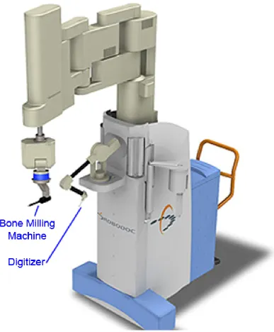
The first robot used for orthopaedic surgery was ROBODOC, shown in Figure 1.8
(Integrated Surgical Supplies Ltd., Sacramento, CA). It was also the first surgical robot
approved by the US Food and Drug Administration (FDA), and was developed at the
University of California-Davis from 1986 to 1992 (38, 39). ROBODOC was an active
robot, designed to assist the surgeon to perform a total hip arthroplasty, with
computer-aided robotic milling devices for accurate implant placement on the femoral bone. The
ROBODOC procedure was performed clinically on human patients in 1991(39, 40). In
hopes of satisfying the needs of the FDA, studies from 1991 to 1998 showed
improvement of fit, fill and alignment of implants statistically compared to conventional
total hip arthroplasty, with accuracy within 0.4 mm and 96% precision (38, 41).
However, ROBODOC complications included longer surgery times and greater learning
curves for the surgeons operating with the robot (38). Also, when the monitoring system
detected an error, the robot stopped its task and corrected the error before proceeding. In
addition, there was a slight increase in blood loss due to the locator pins as a marker
reference used for image guidance anchored on the bone (38). Currently, ROBODOC,
which has been approved over the years, uses surface-matching procedures to replace the
locator pins. It is commercially available by Integrated Surgical Systems Inc., Davis, CA,
Figure 1.8: The Robodoc System1
The left-most arm with the blue band is a bone milling machine, used to prepare the
placement of the implant on the bone. The middle arm is a mechanical arm digitizer with
a stylus probe on the platform for digitization purposes in the pre-operative planning.
1
Active Constraint ROBOT, or ACROBOT (The Acrobot Company Ltd, London, UK), is
another early robot used for orthopaedic surgery (38, 41). ACROBOT used a different
approach than ROBODOC, where ACROBOT allowed the surgeons some control in the
arthroplasty surgery, making the system synergic. ACROBOT was a six DOF articulated
robot arm designed for industrial robot (38, 42), and transformed into a surgical robot.
ACROBOT uses a software-based motion constraint system using force feedback; this
software will ensure that the bone milling process is still in a safe region for the bone
preparation of the knee prosthesis bed (43). There are two skills required to work with
ACROBOT: a skill of the robot to accurately cut flat surfaces in specified positions, and a
skill of the surgeon to judge how much force is need to be applied to cut away the
undesired bone (43). To synergize the two skills, the surgeons have complete control over
the cutting process while the robot prevents the surgeons to damage the soft tissue or
remove too much bone material, and guides the surgeons to registered cuts in the bone
(43). ACROBOT is the first active surgical robot, and it is currently commercially
available for partial knee replacement (40, 42). ACROBOT was recently acquired by
MAKO as part of a settlement in intellectual property litigation (41).
Bone Resection Instrument Guidance by Intelligent Manipulator, or BRIGIT (MedTech
S.A., Montpellier, FR), is an active robot intended for use in total knee arthroplasty (44).
A main functionality of BRIGIT is to lock the knee in position to ensure accuracy of the
knee prosthesis placement. Determining and optimizing the lock position is included in
the patient specific pre-operative planning, to allow surgeons to use their tools to
resurface the bone at a precise angle, and to ensure that the knee prosthesis is accurately
placed without any complications. BRIGIT was developed by MedTech’s Intelligent
Surgical Instrument Technology, acquired by Zimmer in 2006, and cleared for FDA in
2006. However, it was believed that BRIGIT was never used clinically even after
Zimmer announced the availability and price of BRIGIT (44).
MAKOplasty (Mako Surgical, Fort Lauderdale, FL, USA) is a procedure for Robotic arm
Interactive Orthopaedic (RIO) systems; it is a hands-on collaborative device intended for
any orthopaedic joint replacement; so far, however, it has only been performing on total
auditory and haptic feedback, to allow surgeons to mill out bones only in the negative
area from the pre-operative plan (41, 46). This system was FDA approved in May 2005,
and is currently commercialized (44). In 2011, it was reported that there were 36 RIO
systems in operation, and over 2300 procedures performed (41, 44).
With the vision of higher accuracy and precision in mind, the technology of surgical
robots is expanding (38). One of the most recent orthopaedic surgical robots is the
SpineAssist (Mazor Robotics, Caesarea, Israel), a miniature robot used to guide surgeons’
placement of the bone on the vertebra. The SpineAssist is directly mounted onto the bony
anatomy depending on the location obtained from the pre-operative plan, so that the
SpineAssist and the spine can be treated as one rigid body (47). Recently, the FDA
approved the use of the Mazor robot for brain surgery in 2012 due to its precision and
simplicity (48).
1.3 Robots
1.3.1
Definition
A robot is a mechanical structure or manipulator that consists of a set of rigid bodies
connected by a means of articulation (36, 49). In other words, a robot is made up of links
connected by joints. There are two elementary types of joints as shown in Figure 1.9: 1)
rotational (revolute) and 2) translational (prismatic). Each joint has one DOF, and can be
combined to create a complex joint, which will result in more than one DOF. For
example, a Cartesian robot has three prismatic joints to provide translation in three
perpendicular axes, resulting in a three DOF robot. An articulated robot has at least three
rotary joints, which can be used as a robot manipulator or a robotic arm. A robotic arm is
composed of three parts: an arm for mobility, a wrist for dexterity and an end effector for
Figure 1.9: Representation of Revolute and Prismatic Joints
The two types of robot joints are revolute (top) and prismatic (bottom) joints as
illustrated. The revolute joint allows rotation of a joint, whereas the prismatic joint
Furthermore, a robot involves the study of mechanics, electronics, control theory, and
computer science. For example, in computer science, the output of a robotic system is the
actual task ordered by the code, which is monitored by sensors. Control theory allows the
sensors to transmit task information and compare with the prescribed task. The difference
is sent back into the controller, which then sends out information to correct the task in the
actuators; this process is known as a feedback system (50). A mixture of mechanics and
electronics allow sensors to be integrated into the system. The two main types of sensors
found in each joint for this research are position and torque sensors.
Position and impedance controls are two types of robot design algorithm that are used for
this study. Position control is a robot motion control, which allows the user to move the
end effector to the desired location, and to define the path and trajectory planning of the
robot (35). Impedance control is an interaction control, which allows the robot to interact
with the environment, resulting in a collaborative robot with the user. Furthermore,
impedance control regulates the mechanical impedance, such as damping and stiffness
(35).
Currently, robots are widely available for industrial use as they increase productivity and
precision, and decrease labour costs (35). A robot is an autonomous machine capable of
executing a set of programs automatically to carry out actions. Robotics is concerned
with the study of those machines that can replace human beings in the execution of a
task, both physical activity and decision making (36). A robot is used to complete a job
that does not require intelligence, and to make easier the work of humans.
1.3.2
Surgical Robot
Davies defines a surgical robot as ‘a powered computer controlled manipulator with
artificial sensing that can be reprogrammed to move and position tools to carry out a
range of surgical tasks’ (40). This statement implies that the robot will have the
functionalities of surgeons, which is the purpose of having a robot-assisted procedure.
However, the robot will not replace surgeons, as the robots do not have enough
intelligence to carry out the surgery; rather, the robot will be used to assist surgeons to
approach, which will reduce the surgical scar and soft tissue disruption. Also, using a
robot to assist the surgeons help reduce the amount of repetitive tasks to keep surgeons
focused (40).
In general, robotic systems used in surgical procedures are comprised of three phases: a)
pre-operative planning, b) intraoperative intervention, and c) post-operative assessment
(40). In the case of joint arthroplasty, pre-operative planning involves digitizing an
anatomy to create a 3D anatomy model and superimposing the virtual implant model over
the new 3D anatomy model. After superimposing and optimizing the location of the
implant model, negative area, or the overlapped area between the implant model and the
3D anatomy model, can be determined for the drilling process of the robot, and the
operative plan for the robot and the surgeons is created. The second phase is the
intraoperative stage, in which the 3D model has been registered and negative area has
been inputted into the robotic system. The robot will then drill out the negative area for
implant placement. It is important to note that surgeons monitor the process of the robot
to ensure that the operation runs smoothly. Finally, in the post-operative phase, the
assessment is completed, the robot is removed and the patient is released.
There are five key requirements in orthopaedic surgery: 1) safety, 2) accuracy, 3)
sterility, 4) integration in the operating room, and 5) measureable benefits (51). By using
a surgical robot, these requirements can be achieved, and possibly improved. For
example, the first criteria can be implemented by using force measurement; the robot may
sense a force change when the anatomy has been moved. This detection will slow down
or stop the robotic task to avoid any unnecessary problems. The second requirement is
accuracy, and the robot’s accuracy can be comparable to or better than the surgeon’s
accuracy. The accuracy of implant placement by surgeons can range from 0.5 – 1.0 mm,
and in orthopaedic procedures, an accuracy of 1 mm is efficient to carry out the
procedure (51). Finally, due to the high accuracy of the robot, the measureable benefits,
such as less blood loss and hospital stays due to removing only undesirable regions for
minimal soft tissue disruption, can be increased (52).
tasks: passive robot, active robot, synergistic systems, and master-slave ‘telemanipulator’
systems (40). A passive robot is one that is fixed at a location, and is powered down or
locked so that tools can be used at this fixed place. In other words, these robots can be
used as tool holders at appropriate locations. The second classification is an active robot,
in which the robot is programmed to complete the tasks automatically using sensors or
any input commands. For example, an existing robot system for laparoscopic surgery will
assist surgeons by allowing a camera to guide surgeons to view what they desire. This
type of robot requires extensive research and preoperative planning since it has higher
safety concerns as it performs autonomously and is in control of tasks (40). For this
reason, active robots are usually developed specific to a procedure. Surgeons and surgical
robots can work together to create a synergistic system, and this allows the robot to be
collaborative (40, 53). Surgeons can have control over the robot, while the robot restricts
surgeons from unsafe regions. The last classification is the master-slave systems, in
which surgeons have complete control over the robot, and act as masters by using a
joystick or a kinematic mimic system to move the robot manipulator (slave).
1.3.3
Advantages and Disadvantages
There are three main advantages of robot-assisted orthopaedic surgery over conventional
surgery (39). Firstly, the precision of the robot-assisted surgery is approximately an order
of magnitude better than that of the surgeons. The accuracy and safety of procedures
depend on the judgement of the surgeons (51). Secondly, the robot can be more reliable
and produce better outcomes in repeatable tasks. Thirdly, when combined with dynamic
scanning and positioning technology, the robot has great spatial accuracy.
Moreover, the surgical robot can prevent drilling motions into critical regions or allow
motions along a specified direction, such as drilling an angled hole. This is useful for
orthopaedic applications, especially in cases in which drilling bones is a requirement; in
such a case, one must be careful in removing undesired parts, keep the good bones and
ensure that there is minimal soft tissue disruption (40).
However, surgical robots have complications, such as slower adoption rate in clinics, and
the surgical robot is significantly longer than conventional surgery. As a result, the
learning curve for surgeons operating with a robot is significantly greater than without
the use of a robot (52). Longer surgical time can also raise concerns about the correlation
between surgical time and infection risks (41). Also, when the robot monitoring system
detects an error, the robot stops, and has to undergo many processes to confirm whether it
is safe to continue, which will significantly increase surgical times (38). Another
disadvantage of using a surgical robot is, due to the intensive preoperative planning
required for robot navigation, patients are exposed to more radiation by CT scan, which
can raise health concerns (41).
For the robot manipulator to be used in medical applications, there should be a significant
benefit over conventional surgery. Surgeons are reluctant to spend more time in
preoperative planning regardless of the performance of the robotic system. Therefore, it is
necessary to show an improvement in outcomes and cost effectiveness, as well as safety
and ease-of-use, rather than simply focus on the performance of the robot system (54).
1.3.4
Safety Considerations
The latest ISO 10218-1 and 10218-2 standards for robotic safety allow a collaborative
robot to be operated unguarded (53). Collaborative robots contain features such as force
feedback, which allows the robot to safely stop without damaging its surroundings if the
robot detects a collision.
Najmaei et al. (2010) studied the human factors that influence the safety assessment of
robots in an interactive environment (55). Furthermore, Najmaei et al. suggested that a
risk assessment should be used in the path planning process to improve the safety of the
robot system. Primary considerations for the safety of the collaborative robot should
focus on planning and control strategies to avoid collisions with humans. Although
physical factors, such as impact force based on the distance between the robot and human
or obstacles, the relative velocity, and the inertia, are important considerations for
preventing collision and decreasing risk with humans, human factors are also important
This area of research is still in its early stage; however, human factors can provide
intelligence in the decision-making process. For example, by analyzing human body
language, robots can have a feedback system of humans’ cognitive and emotional state
interpretation. This is done to enhance the safety of human-robot interactions. Firstly,
human physiological signals are important factors because they have a significant effect
on the risk of collision. For example, if the user is tired or stressed, then the risk of
collision may significantly increase. Secondly, monitoring the direction of the humans’
eye gaze and body orientation could potentially improve the risk assessment of the robot,
as there is a relation between their focus and awareness of the robot. Najmaei et al.
developed an algorithm to determine a risk index to include in the path planning of the
robot, and found that including the physical and human factors significantly improved the
performance of the robotic system.
1.4 Registration and Digitization
Registration is finding coordinate transformation from one set of data to another, in order
to align important features of both sets of data (56). In the case of computer- or
robot-assisted procedures in orthopaedic surgery, a virtual model of a bone in the joint is
registered to the patient’s computer tomography (CT) scan obtained from the
pre-operative plan. Two main registration algorithms to determine the transformation of two
sets of data or three-dimensional (3D) objects are point-to-point registration and
surface-based registration. Firstly, point-to-point registration, also known as paired point
registration, involves identifying more than three key target points on both 3D objects
before registration (57). Point-to-point registration utilizes the least sum of squares errors
to find the best transformation to align two 3D objects. Secondly, surface-based
registration compares two 3D objects by the point clouds. The most commonly used
surface-based registration is an iterative closest point (ICP) algorithm by, in which the
algorithm finds the closest point in the point cloud of one 3D model to a given point of
the other 3D model, and this is done for all points in both 3D models (58).
Mcdonald et al. (2007) compared three different registration procedures, including
point-to-point, surface-based, and surface-based with noise reduction (59), and found that
the most consistent results, and it was significantly better than the point-to-point
procedure and surface-based with noise reduction.
Moreover, digitization is a representation of a 3D object in a set of points. A digitization
device, or a digitizer, is a tool that measures 3D coordinates into a digital form, providing
3D position (x, y and z coordinates) and orientation (yaw, pitch and roll) data into a
computer system. In this project, a digitizer utilizes a stylus probe to trace over the object,
and the system then converts the digitization of the object into a 3D representation format
readable by a computer; the computer samples the stylus probe movement to transmit
discrete data points at different coordinates (60). A digitization device can be used as a
navigational tracking system in surgery, where the ideal virtual imaging data is registered
to the patient’s CT scan to guide surgical procedures. In orthopaedic surgery, the
digitization device can be used for localization, which is a process of pinpointing the
location of the bony structures and anatomical landmarks.
1.4.1
Digitization Device
Tracking systems can be used as digitizers, as tracking systems are used to monitor six
DOF with respect to a reference point in real-time. Existing tracking systems include
electromagnetic, optical or mechanical arm equipped with a stylus probe (61).
Electromagnetic tracking systems utilize a source, which is a transmitter that generates a
magnetic field using the three orthogonal wire coils in the transmitter, and a receiver,
which detects this signal that will measure the magnetic field and processes this signal in
a computer for analysis. Current electromagnetic tracker systems use a six DOF stylus,
such as a Polhemus Patriot Digitizer (Figure 1.10). The Polhemus Patriot Digitizer uses a
free-form stylus tool, with a cable attached to electromagnetic coils enclosed in a plastic
shell that emits a magnetic field, which is the reference frame for the stylus. The
Figure 1.10: Electromagnetic Tracking System: Polhemus Patriot Digitizer2
The black box in the top left corner is a receiver used to detect the signal transmitted by
the source in the top right corner, and then process this signal in the computer. The
bottom shows a digitizer pen, which is a probe to digitize an object, and is attached to the
source.
2
The optical tracking system is the most commonly used tracking modality (62, 63). The
optical system contains a series of cameras and trackers that can be mounted to track
motions, or equipped with a stylus probe to use as digitizers. Trackers have markers that
are passive or active; passive systems utilize light-reflecting markers and active systems
use light-emitting markers. Wiles et al. (2004) has shown that the difference in the
accuracy between active and passive systems is minimal (64). Optical systems measure
the location and orientation by triangulation and time-of-flight calculation after detecting
the light emitted or reflected from the markers. An example of an optical motion analysis
system is the Optotrak Certus (Figure 1.11). The Optotrak Certus has three cameras and
various trackers with three markers and utilizes a stylus with the tracker attached as a
digitizer. The Optotrak Certus has a marketed accuracy of 0.1 mm.
Finally, a last type of digitizer is a mechanical arm digitizer (Figure 1.12). It consists of
an articulated arm design, sensors in the joints of the linkage chain, and the stylus linked
to the end effector. The sensors determine the relative orientation of the linkage, and with
the known link size and number of joints, the 3D coordinates can be calculated (60, 65).
The Microscribe digitizer is a mechanical arm digitizer with five or six DOF stylus
depending on the model. The Microscribe 3DX reported a marketed accuracy of 0.009”
(0.23 mm). Currently, some surgical robotic systems implement the Microscribe, such as
Robodoc and Acrobot. FARO arm is another mechanical arm digitizer and is a passive
six DOF digitizer, with a 200 mm probe cylinder and a thin shaft at the end. Rohling et
al. (1995) found that the accuracy of the FARO arm is less than 0.5 mm, and that the
FARO arm was comparable to the Optotrak; however, the Optotrak resulted in better
A
B
Figure 1.11: Optical Tracking System: Optotrak Certus3,4
(A) a Certus stylus with three markers in the tracker, (B) three cameras are shown in three
black circles in the horizontal bar in the Optotrak Certus system.
3
Orthopaedic and spine research [Internet]. Waterloo, Ontario: Northern Digital Inc; 2014; cited July 25, 2014. Available from: http://www.ndigital.com/msci/applications/orthopaedic-spine-research/.
4
Figure 1.12: Mechanical Arm Digitizers: Microscribe 3DX5 and FARO Arm6
Pictured are examples of mechanical arm digitizers; the joints in both mechanical arm
digitizers are all revolute. The right side is a Microscribe 3DX, with the digitizing pen in
home position for calibration purposes, and the left side is a FARO arm.
5
Using a touch probe to acquire muscle fibre data [Internet]. Toronto, Ontario: James McCrae; 2008; cited July 25, 2014. Available from: http://www.dgp.toronto.edu/~mccrae/projects/microscribe/.
6
In this thesis, a 7-axis collaborative KUKA robot will be used as a mechanical arm
digitizer. Although the manufacturers of the KUKA robot reported that it has a
repeatability of 0.05 mm, for the purpose of this thesis, it is hypothesized that this KUKA
robot can be competitive with the aforementioned digitizers in this review section. One of
the advantages of using a KUKA robot is the reprogrammability, as the robot has other
purposes than just digitization.
1.4.2
Advantages and Disadvantages of Digitizing Technologies
The advantages and disadvantages of each type of device are outlined in Table 1.1:
Table 1.1: Advantages and Disadvantages of Digitization Devices
Advantage Disadvantage
Optical
• Very high accuracy
• Very high resolution
• Tracked six DOF sensors are relatively large
• Need clear line of sight between source and sensors otherwise measurements are lost
• Camera lens and image distortions and rough handling can decrease accuracy (66)
Electromagnetic
• Flexible due to no clear line-of-sight
• Less expensive than optical tracker
• Accuracy is relatively lower, depending on the placement
• Possible interference of metallic objects (67)
• Wiring can be obtrusive in surgery
Articulated
Arm
• Very high accuracy
• No metal or radio interference
• Low cost
• Small work area
1.4.3
Accuracy Assessments
The two most common standards in validating the accuracy of surgical guidance devices
are the ISO 5725-1:1994 “Accuracy (trueness and precision) of measurement methods
and results” and the ISO 9238 “Manipulating industrial robots – Performance criteria
and related test methods”. Figure 1.13 summarizes the definition of accuracy in ISO
5725-1:1994, and ISO 9238 defines accuracy as the closeness of agreement between a
test result and the accepted reference value. For digitization or surgical navigators,
absolute position accuracy is considered the highest priority (68).
In surgical guidance devices, the literature review suggests dividing the term “accuracy”
into three different types: intrinsic or technical accuracy, registration accuracy and
application accuracy (69, 70). In orthopaedic applications, the technical accuracy applies
to a digitizer as a localizer. The technical accuracy is the average error of the component
in its operational use; in other words, how reliable is the digitizer in defining its own
position in space? The registration error relates to coordinate transformation, where the
fiducial of the markers is registered in image space. Application accuracy reflects the
overall error in the surgical procedure, including technical and registration accuracy. In
general, the acceptable range of the technical, registration and application accuracies
Figure 1.13: Overview of ISO 5725-1:1994
Three different terms are used to summarize ISO 5725:1994. More trueness means that
the targets are closer to the ideal location, which is the black circle in the centre.
Increasing precision shows the targets closer with each other. Accuracy consists of
Methods of validating the accuracy of the digitization device have been developed and
consist of a phantom and a protocol. A study by Koivukangas (2013) was found to be the
most relevant to this thesis (66). Koivukangas had specially designed an accuracy
assessment phantom as shown in Figure 1.14. This phantom has three separate levels
attached with screws to form the total reference volume of 120×120×100 mm. Each level
has 49 points, spaced at 20 mm, and machined with a tolerance of 0.015 mm. Using 17
points on each level, the protocol is to collect coordinate data in x, y and z directions of
each point from point 1 to point 17 on each level. The center point, or point 9 in Figure
1.14, is the reference point. The algorithm is similar to previous studies such as Hummel
el al and Frantz et al (71-73), which is a form of Euclidean Distance of accumulated
measured point and theoretical point. The equation is:
, , , , , ,
Eq. 1
where Xij, Yij, Zij are true values, XM, YM, ZM are measured values and 25 corresponds to
Figure 1.14: Accuracy Assessment Block
Calculations of the mean error, RMS error and 95% confidence interval are, respectively:
Average Error:
∑ Eq. 2
RMS Error:
∑ Eq. 3
95% Confidence Interval:
% ! " # Eq. 4
where $ denotes one standard deviation.
Koivukangas found that low standard deviation may show that the accuracy assessment
block works well. Therefore, for the purpose of this thesis, it was decided to use
Koivukangas’ method to assess the accuracy of the digitization device.