Tool Wear Monitoring when Turning EN 8
Steel with HSS-M2 Tool
Vikas B. Magdum
1, Vinayak R. Naik
2M.E. (Mech) student, Department of Mechanical Engineering, Textile and Engineering Institute, Ichalkaranji, Maharashtra, India1
Professor, Department of Mechanical Engineering, Textile and Engineering Institute, Ichalkaranji, Maharashtra,,India2
Abstract: This paper uses the cutting forces in a turning process of EN 8 steel to estimate the tool wear effect. Tool wear effect is obtained by monitoring the variation in the cutting forces. The aim of this study is to development an on-line monitoring system. By identifying one or more criteria to efficiently quantify and identify rapid tool wear, it can be determined when to change the tool. Tool wear effect is also studied by Finite element Method (FEM) model. The FEM model is designed to carry out stress analysis of the tool.
Keywords: Tool wear, cutting force, stressanalysis, FEM simulation I. INTRODUCTION
This paper presents a critical review of the inhibitors that affect the wastewater treatment in fish processing industry. Since the first works of F.W. Taylor (1850–1915) a great deal has been learnt about tool wear, as it is a widely studied phenomenon. However, the development of new kinds of tools and new materials has expanded the experimental field. This has resulted in a renewed interest in the study of the phenomena of wear. This renewed interest is highlighted by examples of tool wear investigations in different application fields: It is clear that, in a given field, the wear criteria chosen alone should be used to judge reliably when the tool must be removed from service for renewal of the cutting edge. The wear can be defined as the loss of material from the cutting edge due to mechanical or chemical factors associated with the cutting process. Wear minimization has been pursued by different means. An ideal cutting material has to combine high hardness and wear resistance with good toughness and chemical stability, but no material has ever shown all these properties together at their best combination. FEM model was developed to help understanding the wear results found.
based on the updated Lagrangian formulation and the commercial available software, Marc2001, a coupled thermo-mechanical plane-strain large deformation orthogonal cutting FE model is presented to simulate the diamond turning process and predict the residual stresses on the machined surface of workpiece.[13] D. Lu, J.F. Li, Y. Rong, A. Grevstad, S. Usui In this paper, the temperature and the stress distribution in micro-cutting of Ti-6Al-4V and Al-7050-T6 are analyzed by finite element method.[14] C.R. Liu, Y.B. Guo developed a thermo-elastic viscoplastic model using explicit "finite element code Abaqus was to investigate the effect of sequential cuts and tool-chip friction on residual stresses in a machined layer.[15] Raja Kountanya, Ibrahim Al-Zkeri, Taylan Altan The aim was to investigate how the two mechanisms reported in literature namely-surface shear-cracking (SCH) and catastrophic thermoplastic instability (CTI) contribute to overall chip geometry and machining forces.[16]Itaya and Tsuchiya concluded that the direct consequence of the cutting edge wear is the gradual loss of its ability to cut the machined material. The result being an increase in the cutting forces and the machine power consumption. These conditions also result in a poor surface quality. The wear of the cutting edge therefore has a big impact on the cost of the machining process. Furthermore, it is well known in the machining process that, there is a positive correlation between the cutting edge recessing and the increasing of the cutting forces. This gives the opportunity to evaluate the tool wear by measuring cutting forces.
The aim of this study is to development an on-line monitoring system. By identifying one or more criteria to efficiently quantify and identify rapid tool wear, it can be determined when to change the tool and also Study tool wear effect by Finite element Method (FEM) model. The FEM model is designed to carry out stress analysis of the tool
II. EXPERIMENTAL WORK
The cutting tests were performed using a Panther lathe. A strain gauge dynamometer was used to measure the cutting forces. Cutting conditions were feed rate 0.5 mm/rev, depth of cut 1.5mm and cutting speed 572 rpm. Tool geometry is shown in Table 1. The workpieces were EN 8 steel bars with a nominal diameter of Φ30mm and 100mm cutting length.An easy way to comply with the conference paper formatting requirements is to use this document as a template and simply type your text into it.
Ce Cs αb αs θe θs λ R
20 20 0 0 10 10 70 0.4
Table 1 Tool geometry
A lathe was utilized, fitted with a HSS tool. The other parameters were selected in order to obtain prompt treatment and to identify the most appropriate method to analyze the forces. One single sample was prepared and fixed on the Dynamometer for the force acquisitions Fig..1. The other cutting conditions are summarized in Table 2.
Fig. 1 Experimental setup
Cutting speed (rpm) Feed (mm/rev) Depth of cut (mm) 572 0.13 1.5
Table 2 Cutting conditions
Fig. 2 Wear measurement
Sr. No.
Cutting Length (mm)
Cutting force (N) Tool weight
(gm)
Tool weight
loss (gm) Thrust
force (N)
Feed force (N)
1 0 - - 97.557 0
2 20 216 108 97.546 0.011
3 40 304 167 97.531 0.026
4 60 373 206 97.518 0.039
5 80 471 255 97.505 0.052
6 100 579 314 97.492 0.065
Table 3 Measured values of cutting force and tool wear
(a) (b) (c) Fig 3 Wear (a) Initial stage (b)Crater wear (c)Flank wear
Fig. 5 Wear evolution according to cutting length
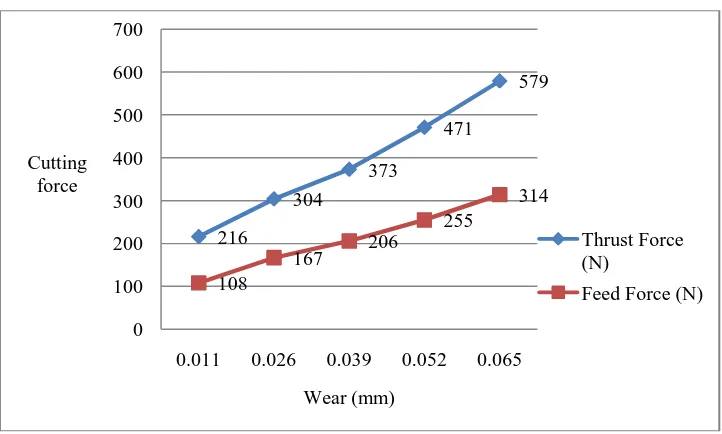
Fig 6 Evolution of Cutting forces according to tool wear
III.STRESS ANALYSIS
A Finite Element Method (FEM) model was developed to illustrate the behaviour of the cutting tool during cutting of EN 8 steel material. The FEM model is simply an aid in understanding the cutting tool. Finite element analysis is a most useful and accurate approach for the determination of field variables that is made possible by advancements in computational and processing power of computers and thus it is almost used for all the computer aided design methodologies in recent years. The Present work is also based on the application of finite element for stress analysis of single point cutting tool for turning operation. Finite Element Method provides insight into the process of manufacturing design. Tool design analysis is conducted through simulation. The stresses acting on tool geometry is evaluated. The stresses acting on tool tip at the onset of machining is studied.
Cutting tool and Workpiece material properties Cutting tool: HSS - M2
Workpiece material: EN 8
0.011 0.026
0.039 0.052
0.065
0 0.01 0.02 0.03 0.04 0.05 0.06 0.07
20 40 60 80 100
Tool weight
loss (gm)
Travel length (mm)
216
304
373
471
579
108
167 206
255
314
0 100 200 300 400 500 600 700
0.011 0.026 0.039 0.052 0.065 Cutting
force
Wear (mm)
Thrust Force (N)
Property HSS - M2 EN 8
Density (Kg/m3) 8600 7800
Youngs Modulus (Gpa) 210 207
Poissons ratio 0.3 0.27
modulus of elasticity (Gpa) 200 207
Hardness 64 HRC 195 BHN
Thermal expansion (/C) 12*10-6 11.5*10-6
Yield strength (MPa) - 510
Tensile Strength (MPa) - 650
Transverse rupture strength
(MPa) 3500 -
Compressive strength(Mpa) 4200 -
Thermal Conductivity W/m/K 21.3 -
Table 4 Cutting tool and Workpiece material properties
In the finite element analysis the basic concept is to analyze the structure, which is an assemblage of discrete pieces called elements, which are connected, together at a finite number of points called Nodes. Loading boundary conditions are then applied to these elements and nodes. A network of these elements is known as Mesh. The Fig. 7(a) shows the boundary and loading condition of model for a single point cutting tool. Finite element model and Loading and Boundary conditions are shown in Fig. 7 (a) and Fig. 7 (b) respectively.
In Fig. 7 (a),
Element type: Solid 186(Higher order tetrahedral) Mesh count: Node-152425, Element-107459. In Fig. 7 (b),
At point A: Forces At point B: Fixed support
(a) (b)
Fig. 7 (a) Finite element model (b) Loading and Boundary conditions.
(a) (b) (c) Fig. 8 (a) Total deformation (b)upture stress (c)Compressive stress
When turning operation is carried out with EN 8 steel as work piece material and HSS-M2 as cutting tool the effective stress and deformation values are noted for different cutting forces. The simulated values of deformation and effective stresses are shown in Fig. 8. The finite element method seems to be the right tool to predict cutting performance including cutting forces, stresses and cutting temperature fields which are often beyond the capability of current measurement methods. Thrust force appears to be the largest force component, while the feed force component is the smallest one. By increasing the tool flank wear, a significant rise of the thrust force component can be observed. Considering a very small contact area on the tool-chip interface, extremely high stresses and temperatures develop on the area.
IV.CONCLUSION
This work provides some interesting results about the tool wear in a machining process of the EN 8: the correlation between the tool wear and cutting forces shows that, the cutting forces are increased as the tool wear increases. The FEM simulations have shown that stress and deformation at the tool can be increases as the tool wear increases.
REFERENCES
[1] H. Aknouche, A. Outahyon, C. Nouveau, R. Marchal, A. Zerizer, J.C. Butaud; “Tool wear effect on cutting forces: In routing process of Aleppo pine wood; journal of materials processing technology,” 209, 2918–2922, 2009.
[2] Reginaldo T. Coelho, Eu-Gene Ng, M.A. Elbestawi, “Tool wear when turning hardened AISI 4340 with coated PCBN tools using finishing
cutting conditions,” International Journal of Machine Tools & Manufactur, 263–272, 47, 2007.
[3] J.A. Ghani, M. Rizal, M.Z. Nuawi, M.J. Ghazali, C.H.C. Haron, “Monitoring online cutting tool wear using low-cost technique and
user-friendly GUI,” Wear, 2619– 2624, 271, 2011.
[4] D.G. Thakur, B. Ramamoorthy, L. Vijayaraghavan “Study on the machinability characteristics of superalloy Inconel 718 during high speed
turning,” Materials and Design 1718–1725, 30, 2009.
[5] Bemhard Sick, “Online tool wear monitoring in turning using Time-delay neural,” 0-7803-4428-6/98, IEEE, 1998.
[6] Zhu Kunpeng, WongYokeSan, HongGeokSoon, “Wavelet analysis of sensor signals for tool condition monitoring: A review and some new
results,” International Journal of Machine Tools & Manufacture, 537–553, 49, 2009.
[7] R.P. Martinho, F.J.G. Silva, A.P.M. Baptista, “Wear behaviour of uncoated and diamond coated Si3N4 tools under severe turning conditions,”
Wear, 1417–1422, 263, 2007.
[8] Sanjay Rawat, Helmi Attia, “Wear mechanisms and tool life management of WC–Co drills during dry high speed drilling of woven carbon
fibre composites,” Wear, 1022–1030, 267, 2009.
[9] Ildiko mankova, “Contribution to the knowledge about cutting tool condition monitoring via force signals,” research grant projects Vega no.
1/9401/02 and no. 1/0420/03 supported by Scientific Grant Agency of the Ministry of Education of Slovac Republic and the Slovac Academy of Science.
[10] Xiaoli Li, “Real-time tool wear condition monitoring in turning,” International International Journal of Production Research ISSN 0020–
7543, VOL. 39, NO. 5, 981–992, 2001.
[11] A. Simoneau, E. Ng, M.A. Elbestawi, “Chip formation during microscale cutting of a medium carbon steel,” International Journal of Machine
Tools & Manufacture, 467–481, 46, 2006.
[12] J. Pujana, P.J. Arrazola, J.A. Villar; In-process high-speed photography applied to orthogonal turning,” journal of materials processing technology, 475–485, 202, 2008.
[13] W.J. Zong, T. Sun, D. Li, K. Cheng, Y.C. Liang, “FEM optimization of tool geometry based on the machined near surface’s residual stresses
generated in diamond turning,” Journal of Materials Processing Technology 271–278, 180, 2006.
[14] D. Lu, J.F. Li, Y. Rong, A. Grevstad, S. Usui, “Temperature and stress analysis in Micro-cutting of TI-6AL-4V and AL7050-T6 with
advantage”.
[15] C.R. Liu, Y.B. Guo, “Finite element analysis of the effect of sequential cuts and Tool-chip friction on residual stresses in a machined layer,”
International Journal of Mechanical Sciences, 1069-1086, 42, 2000.
[16] Raja Kountanya, Ibrahim Al-Zkeri, Taylan Altan, “Effect of tool edge geometry and cutting conditions on experimental and simulated chip