726+,%$
Telecommunication Systems Division
Digital Business Telephone Solutions
System Record Sheets
Software Release 4.1
and ACD
Software Release 3.1
Publication Information
Toshiba America Information Systems, Inc., Telecommunication Systems Division, reserves the right, without prior notice, to revise this information publication for any reason, including, but not limited to, utilization of new advances in the state of technical arts or to simply change the design of this document.
Further, Toshiba America Information Systems, Inc., Telecommunication Systems Division, also reserves the right, without prior notice, to make such changes in equipment design or components as engineering or manufacturing methods may warrant.
© Copyright 1999
Toshiba America Information Systems, Inc.
Telecommunication Systems Division
All rights reserved. No part of this manual, covered by the copyrights hereon, may be reproduced in any form or by any means—graphic, electronic, or mechanical, including recording, taping, photocopying, or information retrieval systems—without express written permission of the publisher of this material.
Stratagy is a registered trademark of Toshiba America Information Systems, Inc. Strata
Strata DK
General End User Information
The Strata DK Digital Business Telephone System is registered in accordance with the provisions of Part 68 of the Federal Communications Commission’s Rules and Regulations.
FCC Requirements
Means of Connection: The Federal Communications Commission (FCC) has established rules which permit the Strata DK system to be connected directly to the telephone network. Connection points are provided by the telephone company— connections for this type of customer-provided equipment will not be provided on coin lines. Connections to party lines are subject to state tariffs.
Incidence of Harm: If the system is malfunctioning, it may also be disrupting the telephone network. The system should be disconnected until the problem can be determined and repaired. If this is not done, the telephone company may temporarily disconnect service. If possible, they will notify you in advance, but, if advance notice is not practical, you will be notified as soon as possible. You will be informed of your right to file a complaint with the FCC.
Service or Repair: For service or repair, contact your local Toshiba telecommunications distributor. To obtain the nearest Toshiba telecommunications distributor in your area, call Toshiba America Information Systems, Inc., Telecommunication Systems Division in Irvine, CA (949) 583-3700.
Telephone Network Compatibility: The telephone company may make changes in its facilities, equipment, operations, and procedures. If such changes affect the compatibility or use of the Strata DK system, the telephone company will notify you in advance to give you an opportunity to maintain uninterrupted service.
Notification of Telephone Company: Before connecting a Strata DK system to the telephone network, the telephone company may request the following: 1. Your telephone number.
2. FCC registration number:
♦ Strata DK may be configured as a Key or Hybrid telephone system. The appropriate configuration for your system is dependent upon your operation of the system.
♦ If the operation of your system is only manual selection of outgoing lines, it may be registered as a Key telephone system.
♦ If your operation requires automatic selection of outgoing lines, such as dial access, Least Cost Routing, Pooled Line Buttons, etc., the system must be registered as a Hybrid telephone system. In addition to the above, certain features (tie Lines, Off-premises Stations, etc.) may also require Hybrid telephone system registration in some areas.
♦ If you are unsure of your type of operation and/or the appropriate FCC registration number, contact your local Toshiba telecommunications distributor for assistance.
DK14 and DK40i
Key system: CJ6MLA-74479-KF-E
Hybrid: CJ6MLA-74478-MF-E
DK424
Hybrid: CJ69XA-10243-MF-E
Key system: CJ69XA-10242-KF-E
PBX: CJCHN-22757-PF-E
3. Ringer equivalence number: 0.3B. The ringer equivalence number (REN) is useful to determine the quantity of devices which you may connect to your telephone line and still have all of those devices ring when your number is called. In most areas, but not all, the sum of the RENs of all devices connected to one line should not exceed five (5.0B). To be certain of the number of devices you may connect to your line, as determined by the REN, you should contact your local telephone company to ascertain the maximum REN for your calling area.
RJ48C, RJ48X, RJ11, RJ14C, RJ21X (see Network Requirements in this document). Items 2, 3 and 4 are also indicated on the equipment label.
Radio Frequency Interference
Warning: This equipment generates, uses, and can radiate radio frequency energy and if not installed and used in accordance with the manufacturer’s instruction manual, may cause interference to radio communications. It has been tested and found to comply with the limits for a Class A computing device pursuant to Subpart J of Part 15 of FCC Rules, which are designed to provide reasonable protection against such interference when operated in a commercial environment. Operation of this equipment in a residential area is likely to cause interference, in which case, the user, at his/her own expense, will be required to take whatever measures may be required to correct the interference.
This system is listed with Underwriters Laboratory.
UL Requirement: If wiring from any telephone exits the building or is subject to lightning or other electrical surges, then secondary protection is required. Secondary protection is also required on DID, OPS, and tie lines. (Additional information is provided in this manual.)
Important Notice — Music-On-Hold
In accordance with U.S. Copyright Law, a license may be required from the American Society of Composers, Authors and Publishers, or other similar organization, if radio or TV broadcasts are transmitted through the music-on-hold feature of this telecommunication system. Toshiba America Information Systems, Inc., hereby disclaims any liability arising out of the failure to obtain such a license. CP01, Issue 8, Part I Section 14.1
Notice: The Industry Canada label identifies certified equipment. This certification means that the equipment meets certain telecommunications network protective, operational and safety requirements as prescribed in the appropriate Terminal Equipment Technical Requirements document(s). The Department does not guarantee the Equipment will operate to the user’s satisfaction.
Before installing this equipment, users should ensure that it is permissible to be connected to the facilities of the local telecommunications company. The equipment must also be installed using an acceptable method of connection. The customer should be aware that compliance with the above conditions may not prevent degradation of service in some situations.
Repairs to certified equipment should be coordinated by a representative designated by the supplier. Any repairs or alterations made by the user to this equipment, or equipment malfunctions, may give the telecommunications company cause to request the user to disconnect the equipment.
Users should ensure for their own protection that the electrical ground connections of the power utility, telephone lines and internal metallic water pipe system, if present, are connected together. This precaution may be particularly important in rural areas.
CAUTION! Users should not attempt to make such connections themselves, but should contact the appropriate electric inspection authority, or electrician, as appropriate.
CP01, Issue 8, Part I Section 14.2
Notice: The Ringer Equivalence Number (REN) assigned to each terminal device provides an indication of the maximum number of terminals allowed to be connected to a telephone interface. The terminal on an interface may consist of any combination of devices subject only to the requirement that the sum of the Ringer Equivalence Numbers of all the Devices does not exceed 5.
Contents
Introduction
Organization ... vii
New Format...viii
Conventions...viii
Related Documents ... ix
Chapter 1 – Initialization & Test
Program 91-9 – System Initialization ... 1
Program 90 – Initialize Programs 00~*99 ... 1
Program 91-1 – Automatic PCB Recognition and Port Renumber... 2
Program 91-2 – Data Transfer from Temporary Memory to Working Memory ... 2
Program 92 – Initializing Misc. Backup RAM ... 3
Program 00 – Part 1: Software Check... 4
Program 00 – Part 2: Processor RAM Test ... 5
Chapter 2 – System & Station
Program 01 – Station Logical Port Display and/or Change ... 7
Program 02 – Station Physical Port Display and/or Change... 8
Program 03 for DK14 – Slot Assignments ... 8
Program 03 for DK40i – Flexible PCB Slot Assignments... 9
Program 03 for DK424 – Flexible PCB Cabinet Slot Assignments ... 10
Program *03 for DK424 – Cabinet Type Identification ... 12
Program 04 – Station Logical Port [PDN] Assignment ... 13
Program *04 – [PhDN] and Distributed Hunt [DN] Assignments For Internal and Tie Line Calls... 16
Program 05 – Flexible Access Code Numbering ... 17
Program *05 – Call Park Pickup Abbreviated Dialing ... 19
Program 09 – Built-in Auto Attendant Prompt / Station Assignments ... 19
Program *09 – [PDN], [PhDN], DH, ACD or Modem DID Ext. Assignments ... 20
Program 10-1 – System Assignments, Part 1 of 3 ... 21
Program 10-2 – System Assignments, Part 2 of 3 ... 22
Program 10-3 – System Assignments, Part 3 of 3 ... 23
Program *10 – Enhanced 911 Operation ... 24
Program 12 – System Assignments, Basic Timing... 25
Program 13 – Defining the Message Center ... 26
Program 15 – Ground/Loop/Tie/DID Line Options... 27
Program *15 – CO Line Tenant Assignments ... 28
Chapter 2 – System & Station
Program 19 – Alternate Background Music Source Slot Assignment ... 32
Program 20 – Computer and Data Interface Unit Configuration ... 32
Program 21 – Modem Pool Port Assignments... 33
Program 22 – RPCI and DIU Station Hunting for Data Calls ... 34
Program 23 – Built-in Auto Attendant (AA) Primary Announcement Assignments ... 35
Program 24 – Built-in AA Secondary Announcement Assignments... 35
Program 25-1 – Built-in AA Incoming Call Overflow Time... 36
Program 26 – Built-in AA Camp-on Busy Time ... 37
Program 27 – DKT Handset/Headset Receiver Volume Level ... 38
Program 28 – DSS Console/Attendant Telephone Assignments ... 39
Program 29-1~8 – DSS Console and Number Button Assignments... 40
Program *29 – Add-on Modules Button Assignments ... 42
Program 30 – Station Class of Service... 44
Program *30 – Telephone Group Page Assignments ... 45
Program 31 – Station Class of Service... 46
Program *31 – Group Pickup Assignments ... 47
Program 32 – Automatic Preference ... 48
Program *32 – RS-232 Voice Mail Message Center Port ... 49
Program 33 – [PDN]/ [PhDN] Station Hunting (Voice Calls Only)... 50
Program *33 – [PhDN] Owner Telephone Assignment ... 51
Program 34 – Hold Recall Timing ... 52
Program *34 – Station Class Of Service... 53
Program 35 – Station Class of Service... 54
Program 36 – Fixed Call Forward... 55
Program *36 – System NT Button Lock Password Changing Station Assignment ... 56
Program 37 – Ring Transfer (Camp-on) Recall Time ... 57
Program *37 – Park Recall Timing... 58
Program 38 – Digital and Electronic Telephone Keystrip Type... 59
Program *38 – Standard Telephone Ring-Down Destination... 63
Program 39 – Flexible Button Assignments ... 64
Program *40 – Distributed Hunt Group Member Assignments... 70
Program *41 for DK424 – T1 Assignment Series (Part 1) ... 71
Program *50 – Caller ID Circuit Assignments to CO Line PCBs ... 74
Program *51 – Station Memory Allocation ... 75
Program *52 – Caller ID/ANI Abandoned Call Number Station Owner Assignments... 76
Program 58 – DK424 Attendant Console Series (Part 1) ... 77
Program 59 – Attendant Console Flexible Button Codes ... 79
Program 60-1 – SMDR Data Output Options ... 84
Program 60-2~7 – SMDR Output/Account Code Digit Length ... 85
Program 60-8 – Call Forward External (Remote Change, Security) ID Code... 86
Program 69 – Verified Account Codes ... 87
Program 70 – Verified Account Code Toll Restriction Assignments... 88
Program 71 DNIS... 89
Program *71~*73 – [DN] to [DN], Tie to [DN], and DID to [DN] Ringing Assignments ... 91
Chapter 3 – Toll Restriction
Program 77-3 – Night Ringing Over PIOU External Page Zones ... 97
Program 77-4 – RSIU Open Architecture Interface (OAI) Data Output Assignments... 98
Program 78 – CO Line Special Ringing Assignments... 99
Program 79 – Door Phone Ringing ... 100
Program 80 – EKT and DKT Ringing Tones (CO Line Calls)... 102
Program *80 – Call Forward Station Ring Assignment... 103
Programs 81~89 – Ground/Loop Start/CO Line Station Ringing... 104
Programs *81, *84, and *87 – Ground/Loop Start/CO Line to [DN] LED Flash Assignments... 105
Program 93 – CO Line Identification... 106
Program 97 – Printing Program Data through SMDR ... 107
Chapter 3 – Toll Restriction
Program 40 – Station CO Line Access ... 110
Program 41 – Station Outgoing Call Restriction ... 111
Program 42-0 – CO Line to PBX/Centrex Connection & Access Codes ... 112
Program 42-1~8 – PBX/Centrex Access Codes... 113
Program 43 – 0 + Credit Card Dialing Option...114
Program 44-1~8 – Toll Restriction/Traveling Class Override Codes... 115
Program 44-91~93 – Emergency Bypass of Forced/Verified Account Codes ... 116
Program 45-1 – LCR/Toll Restriction Dial Plan... 117
Program 45-2 – Toll Restriction Disable ... 118
Program 45-3~6 – Special Common Carrier Numbers and Authorization Code Digit Length... 119
Program 45-8~9 – Toll Restriction Override Code ... 119
Program *45-1 (1~4) – Toll Restriction for Office Codes... 120
Program *45-2 (1~6) – LCR/Toll Restriction Bypass ... 120
Program *45-3 (1~9) – LCR/Toll Restriction Bypass For Special Numbers that Begin with */# ... 121
Program *45-4 – Special Code Dialing Sequence with LCR ... 121
Program 46-2~4 – Toll Restriction Allowed/Denied Area Codes by Class ... 122
Program 46-6~8 – Toll Restriction Allowed/Denied Local Office Codes Assigned by Class ... 123
Programs 46-10~80 – Toll Restriction Class Parameters ... 124
Programs 46-11~46-81 – Toll Restriction Class (1~8) Parameters ... 125
Program 47 – Toll Restriction Exception Office Codes Assigned by Area Codes (Tables 1~16) ... 126
Program 48 – Station Toll Restriction Classification ... 127
Chapter 4 – Least Cost Routing
Program 50-1 – LCR Parameters ... 129
Program 50-2 – LCR Home Area Code ... 129
Programs 50-3 (1~5) – LCR Special Codes... 130
Program 50-4 – LCR Long Distance Information (LDI) Plan Number ... 130
Program 50-5 – LCR Local Call Plan Number ... 131
Program 50-6 – LCR Dial 0 (Zero) Time-out ... 131
Program 51 – LCR Area Codes ... 132
Program 52 – LCR Office Code Exceptions for Specified Area Code... 133
Program 53 – LCR Schedule Assignments for LCR Plans... 134
Program 54 – LCR Route Definition Tables... 135
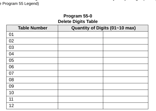
Program 55 – LCR Modified Digits Table ...135
Chapter 5 – Automatic Call Distribution
Program 55-1 and 2 – Add Digits Before and/or After the Dialed Number ... 137
Program 56 – LCR Station Group Assignments ... 138
Chapter 5 – Automatic Call Distribution
Program 03 – RSIU, RSSU, PIOU, PIOUS ACD/MIS Slot Assignments ... 139
Program 09 – Auto Attendant Prompt/ACD Group Assignments ... 140
Program *09 – ACD Group DID Line Digit Assignments ... 141
Program 10-4 – ACD/ISDN Parameters ... 142
Program 11 – ACD Timing Assignments ... 143
Program 14-0 – Loop/Ground Start Line Direct to ACD Group Assignments... 144
Program 14-1 – ACD Agent Identification Code Assignments ... 144
Program *14-1 – Auto Answer with Zip Tone Assigned to Agent ID ... 145
Program 18 – Agent Names for SMIS/MIS Assignments ... 145
Program 14-2 – ACD Supervisor Passwords ... 146
Program *14-2 – DID, Tie, DNIS, ANI Line After Shift/Overflow Substitution Destinations ... 147
Program 14-3 – Announcement/Music Port and Queue Pattern ... 148
Program 14-4 – Queue Time Out Overflow Destination ... 149
Program 14-5 – Overflow Point and Ring No Answer Routing Destination... 150
Program 14-6 – After Shift Service Destination ... 151
Program 14-71 – Queue Size for Alarm, Immediate Assignments... 152
Program 14-72 – Queue Size for Alarm 1 ... 153
Program 14-73 – Queue Size for Alarm 2 ... 154
Program 14-8 – Alarm Pattern Assignments ... 155
Program 14-9 – Work Unit Assignments ... 155
Program 15 – Ground/Loop/Tie/DID Line Options... 156
Program 17 – DID/Tie Line Options ... 156
Program 35 – Station Class of Service... 156
Program 71 – DID/Tie/DNIS/ANI Lines ... 156
Program 39 – Flexible Button Assignments for ACD Telephones... 157
Chapter 6 – ISDN
Program 16 – Assign CO Line Groups ... 161
Program *16 – ISDN Trunk Group Type Assignment ... 161
Program *42 – Clock Source ... 162
Program *42-1 – Primary Timing Reference Assignments (Release 3.1 and earlier) ... 162
Program *43-1~3 – D-Channel Control and NFAS Assignments ... 163
Program *43-2 – Non-Facility Associated Signaling (NFAS) Assignment ... 163
Program *43-3 – Network PRI Interface Assignment ... 163
Program *44 – BRI Service Profile Identifier (SPID) Parameters ... 164
Program *60 – BRI Line/Station Operation Assignment ... 165
Program *61 – Analog Trunk Services for ISDN ... 166
Program *62 – Non-ISDN Station Bearer Service ... 167
Program *63 – ISDN Dialing Parameters ... 168
Chapter 7 – E911
Program *66-3 – Channel Group/Trunk Parameters ... 173
Program *66-5 – Line Directory Number (LDN) Registration ... 174
Program *66-6 – LDN/Trunk Group to Channel Group Assignments ... 175
Program *66-7 – LDN/Trunk Group Assignments... 176
Program *67-1 – Trunk Group Call Direction ... 177
Program *67-2 – Call Types for ISDN Trunk Group Supported... 178
Program *67-3 – ISDN Trunk Group Minimum Channel Reservation ... 179
Program *67-4 – ISDN Trunk Groups Maximum Channel Reservation... 180
Program *67-5 – Multiple Time Zone Settings ... 180
Program *68-1 – Calling Number ID Presentation Parameters ... 180
Program *68-2 – Outbound CNIS Parameters... 181
Program *69-1 – CNIS Presentation Parameters ... 182
Program *69-2 – Special Number Assignment... 183
Chapter 7 – E911
Program *11-0 – E911/CAMA Trunk Assignments ... 185
Program *11-1 – CAMA Trunk Group Line Assignments... 186
Program *11-2 – CAMA Trunk Group Hunting Assignments ... 186
Program *11-5 – CAMA Digits Sent on 911 Calls... 187
Program *11-6 – E911 Interdigital Timer ... 187
Program *11-8 – 911 Special [DN] Notification Assignments ... 188
Program *12 – CESID Station Information ... 189
Introduction
These record sheets enable you to program the Strata DK14, DK40i, and DK424 digital business
telephone systems. They are intended for qualified service technicians and system programmers.
At the time of this printing, this book contains Release 4.1 information for the DK424. It also
contains some pre-release information for software beyond Release 4.1.
Important!
Information beyond Release 4.1 is preliminary and given prior to product release.
Be careful when using this information as the software will change and updates/
additions will be required upon final release.
Record sheets and detailed information about each program can be found in the Strata DK
Programming Manual. The DK Installation and Maintenance Manual also contains useful
information. Both of these books can also be found on the Strata DK Library CD-ROM.
Organization
This manual is organized as follows for your convenience:
♦
Chapter 1 – Initialization & Test includes information for initializing and test programs.
♦Chapter 2 – System & Station includes programming information for the entire system and
individual stations.
♦
Chapter 3 – Toll Restriction includes programming information for Toll Restriction.
♦
Chapter 4 – Least Cost Routing includes programming information for Least Cost Routing.
♦Chapter 5 – Automatic Call Distribution includes ACD programming for DK424 (ACD
does not apply to the RCTUA processor).
♦
Chapter 6 – ISDN includes programming instructions and record sheets for Integrated
Systems Digital Networking features for the DK424 and DK40i.
♦
Chapter 7 – E911 includes programming information for connecting the DK424 to Enhanced
911 CAMA trunks.
Conventions
Conventions
Conventions
Description
Note
Elaborates specific items or references other information. Within
some tables, general notes apply to the entire table and numbered
notes apply to specific items.
Important!
Calls attention to important instructions or information.
CAUTION!
Advises you that hardware, software applications, or data could be
damaged if the instructions are not followed closely.
WARNING!
Alerts you when the given task could cause personal injury or
death.
[DN]
Represents any Directory Number button, also known as an
extension or intercom number.
[PDN]
Represents any Primary Directory Number button (the extension
number for the telephone).
[SDN]
Represents any Secondary appearance of a PDN. A PDN which
appears on another telephone is considered an SDN.
[PhDN]
Represents any Phantom Directory Number button (an additional
DN).
$ULDO
#
%ROG
Represents telephone buttons.
Courier
Shows a computer keyboard entry or screen display.
“Type”
Indicates entry of a string of text.
“Press”
Indicates entry of a single key. For example: Type
prog
then
press
Enter
.
Plus (+)
Shows a multiple PC keyboard or phone button entry. Entries
without spaces between them show a simultaneous entry.
Example:
Esc
+
Enter
. Entries with spaces between them show
a sequential entry. Example:
#
+
5
.
Tilde (~)
Means “through.” Example: 350 ~ 640 Hz frequency range.
➤
Denotes the step in a one-step procedure.
➤
Denotes a procedure.
Used in a programming sequence to denote a variable LED button.
A number on the black button represents a specific LED button.
Indicates continuation of a series of numbers entered.
Related Documents/Media
Related Documents/Media
Note
Some documents listed here may appear in different versions on the CD-ROM, FYI or in
print. To find the most current version, check the version/date in the Publication
Information on the back of the document’s title page.
The following documents and CD-ROMS can be used to reference further information about the
Strata DK systems.
♦
Digital Telephone User Guide provides all the procedures necessary to operate
Toshiba-proprietary digital telephones, including Liquid Crystal Display (LCD) features. It also
includes instructions for using the add-on module/DSS console.
♦
Digital Telephone Quick Reference Guide provides a quick reference for frequently-used
digital telephone features.
♦
Digital Single Line Telephone User Guide provides all the procedures necessary to operate
Toshiba-proprietary digital single line telephones.
♦
Electronic Telephone User Guide explains all the procedures necessary to operate
Toshiba-proprietary electronic telephones, including all LCD features. Does not apply to the Strata
DK14 system. It also includes instructions for using the electronic DSS console.
♦
Electronic Telephone Quick Reference Guide provides a quick reference for
frequently-used electronic telephone features. Does not apply to the Strata DK14 system.
♦
Standard Telephone User Guide explains all the procedures necessary to operate rotary dial
and push-button standard telephones.
♦
Strata AirLink External Wireless Handset User Guide shows how to use the wireless
handset configured to standard ports of the Strata DK telephone system and many non-Toshiba
systems.
♦ ♦ ♦
♦
Strata AirLink External Wireless Quick Reference Guide contains instructions for
operation of commonly used Strata AirLink External Wireless Handset features.
♦
Strata AirLink Integrated Wireless Handset User Guide shows how to use the wireless
handset configured to digital ports of the Strata DK telephone system.
♦ ♦ ♦
♦
Strata AirLink Integrated Wireless Quick Reference Guide contains instructions for
operation of commonly used Strata AirLink Integrated Wireless Handset features.
♦
System Administrator Guide gives instructions for the System Administrator to manage the
system. Contains instructions for Station Relocation, System Speed Dial, and other features
only activated by the System Administrator.
♦
PC/Data Interface User Guide explains all the procedures necessary to operate stand-alone
data interface units while in the data mode for printer sharing and modem pooling. Also
provides instructions on connecting to a Personal Computer with Telephone Application
Programming Interface (TAPI).
♦
Cordless Telephone User Guide provides instructions on using the DKT2004-CT cordless
digital telephone as a single unit or in conjunction with a digital telephone.
♦
PC-DKT User Guide provides installation and operation information for the Personal
Computer Digital Key Telephone system.
Related Documents/Media
♦
Keyprint 2000 User Guide provides instructions for the Keyprint 2000 software printing
package which allows you to print and store custom button label keystrips for Strata DK
2000-series 10-button or 20-button digital telephones, 20-button add-on modules, and 60-button
digital DSS consoles.
♦
Strata DK Programming Manual provides all instructions necessary to program the system
and system record sheets, including ACD.
♦
Strata DK Installation & Maintenance Manual provides installation instructions for
configuring and installing the Strata DK14, DK40i and DK424. It also includes T1/DS-1
interface installation and configuration instructions, as well as fault finding flowcharts to
troubleshoot the systems. An ACD Section provides instructions for installing ACD into the
Strata DK424.
♦
Strata AirLink External Wireless System Installation Guide provides step-by-step
hardware and software installation instructions. It includes examples of system configurations,
information on performing a site survey, and troubleshooting techniques.
♦
Hospitality Management Information System (HMIS) General Description provides an
overall view of the system’s hardware, software, applications and features. The HMIS is a
PC-based solution, designed to meet the specific operational needs of small- to medium-sized
hotel/motels and includes both the PC and software.
♦
Hospitality Management Information System (HMIS) User Guide describes the product’s
many software features and gives step-by-step instructions for using them.
♦
Strata DK Library CD-ROM enables you to view, print, navigate and search publications
for Strata DK14, DK40 and DK424 digital business telephone systems. It also includes Strata
DK424 ACD Documentation, including the DK424 Call Center Solutions General
Description, ACD Agent Guide, ACD Supervisor’s Guide. ACD Installation and Programming
instructions are included in the Strata DK Installation and Maintenance Manual and
Programming Manual.
♦
Strata DK HMIS CD-ROM contains a copy of all HMIS documentation/bulletins and
enables you to view, print, navigate and search publications.
♦
StrataControl CD-ROM contains the StrataControl software, that enables viewing,
downloading, editing, and uploading Strata DK programmed data on a PC. This software also
provides a method of creating custom lists and user guides based on information from the
Strata DK system.The CD-ROM contains the StrataControl User Guide.
♦
DKQuote CD-ROM contains the DKQuote application and the DKQuote User Guide, that
shows how to use this interactive software to assist you with Strata DK Systems configuration
and pricing worksheets.
♦
DKAdmin/DKBackup CD-ROM includes the programs that let you easily and quickly
custom program and/or update the Strata DK14/DK40/DK424 with a user-friendly PC display.
The CD-ROM also contains the DKAdmin/DKBackup User Guide, that explains how to use
the DKAdmin/DKBackup interactive software applications. The current version does not
work with DK40i.
The following documentation and media applies to the Strata DK424 system only.
♦
Strata DK424 Call Center Solutions General Description provides a system overview,
Related Documents/Media
♦
Insight DK CD-ROM which includes training, all Insight DK documentation, Insight DK
software and the upgrade to Insight DK Plus, and Demo software.
♦ ♦ ♦
♦
Insight DK Installation Guide explains how to set up the network, install the server software,
install clients and explains how the data files are organized.
♦ ♦ ♦
♦
Insight DK Supervisor Guide provides instructions for using the Strata DK Insight and
Insight DK Plus MIS for the Supervisor of a call center. Instructions for creating and using
Real Time Displays, Reports, Alarms, and Wallboards are also included.
♦ ♦ ♦
♦
Insight DK inView Quick Reference Guide provides instructions for viewing and
customizing the on-screen wallboard and large character views of the real time call center
data.
♦
PC Attendant Console User Guide explains the procedures necessary to operate the PC
Attendant Console.
♦
PC Attendant Console Quick Reference Guide provides a quick reference for
frequently-used PC Attendant Console features.
♦
Call Center Viewer User Guide describes how to install and operate the Call Center Viewer
application on a PC. It explains how to view and customize ACD group and agent status
information.
♦
Software MIS (SMIS) Supervisor Manual provides descriptions, examples, and instructions
on using the Software MIS application.
Initia
liz
atio
n & T
e
s
t
Initialization & Test
1
Program 91-9 – System Initialization
Processor Type:
DK14, DK40i, All RCTUs
Program Type:
Initialization
Initialized Default:
See individual programs
Program 90 – Initialize Programs 00~*99
Processor Type:
DK14, DK40i, All RCTUs
Program Type:
Initialization
Initialized Default:
See individual programs
6SNU +ROG 6SNU +ROG Program Telephone Exits Program Mode
6SNU +ROG 6SNU +ROG 6SNU +ROG 6SNU +ROG
Repeat a second time after LEDs 01, 03, 05, 07, and 09 extinguish.
Enter programming mode. (Do not press [DN] button.)
Press Buttons 01, 03, 05, 07, and 09. LEDs 01, 03, 05, 07, and 09 must be ON. LCD Displays:
SYSTEM INITIALIZATION
Enter programming mode
Press LED Buttons 01 and 02 LEDs 01 and 02 must be ON Programs to be initialized. Add a range of program numbers by entering XX*XX or XX**XX.
Exit programming mode End Program 90
Program 91-1 – Automatic PCB Recognition and Port Renumber
Program 91-1 – Automatic PCB Recognition and Port
Renumber
Processor Type:
DK14, DK40i, All RCTUs
Program Type:
Initialization
Initialized Default:
None
Program 91-2 – Data Transfer from Temporary Memory
to Working Memory
Processor Type:
DK14, DK40i, All RCTUs
Program Type:
Initialization
Initialized Default:
See individual programs
6SNU +ROG 6SNU +ROG Program Telephone Exits Program Mode
6SNU +ROG 6SNU +ROG Program Telephone Exits Program Mode and Transfers Data Enter programming mode.
(Do not press [DN] button.)
Press LED Buttons 01 and 02. LEDs 01 and 02 must be ON. LCD Displays:
91 SELECT = 1
Renumber and Reset
Enter programming mode. (Do not press [DN] button.)
Press LED Buttons 03 and 04. LEDs 03 and 04 must be ON. LCD Displays:
91 SELECT = 2
Programming
Initia
liz
atio
n & T
e
s
t
Program 92 – Initializing Misc. Backup RAM
Program 92 – Initializing Misc. Backup RAM
Processor Type:
DK14, DK40i, All RCTUs
Program Type:
Initialization - Includes: Initializing Speed Dial Number, VM ID Codes, Character
Message Memory, Timed Reminders, Digital Telephone Volume, Called ID, ANI, and
Call Forward Backup RAM
Initialized Default:
See individual programs
6SNU +ROG 6SNU +ROG 6SNU +ROG 6SNU +ROG
Clears Station Speed Dial, Voice Mail ID Codes, and LCD memos assigned to Station Speed Dial numbers.
Clears System Speed Dial and LCD memos assigned to System Speed Dial numbers.
Clears Character Message Memory (Station and System) and User Name/Number Display.
Clears Timed Reminders.
Resets digital telephone volume levels to initialized settings, specifically, speaker volume levels for Internal Calls [DN], Tone/BGM, Busy Override (muted ring), and Ring volume to approximately mid-range on all DKTs. Program 92-5 does not affect digital telephone handset receiver volume levels. Use Program 27 to set off-hook digital telephone handset receiver volume levels.
+ROG Power OFF 5 seconds; then Power ON
Clears Call Forward and Message Waiting Memory (all stations). Program 92-9 does not affect Call Forward External or Fixed Call Forward settings. Clear more data
Enter programming mode.
SELECT = Press appropriate buttons as shown below.
Exit programming mode.
Program 00 – Part 1: Software Check
Program 00 – Part 1: Software Check
Processor Type:
DK14, DK40i, All RCTUs
Program Type:
Test - Includes: Remote Maintenance Security Code Assignments
Initialized Default:
None
6SNU +ROG 6SNU +ROG 6SNU +ROG 6SNU +ROG
Select = Code
Item
Password or S/W
Check Codes
LCD Display
0
ROM Version (not programmable)
Version =
1
1st Level Password
Password =
2
2nd Level Password
Password =
8
Software RAM Checksum (not programmable)
Sum =
9
Power Cycle Counter (not programmable)
Counter =
DKT LCD Display
RCTU Type
Key Type
Description
WMA4
DK14
KEY 1
AA: Indicates built-in Auto Attendant software
(RKYS1, KKYS, or QKYS installed).
TMA4
DK40i
KEY 2
ACD: Indicates Automatic Call Distribution
software and AA (RKYS2 installed).
RAA3X
RCTUA3
KEY 3
ACD/MIS: Indicates Automatic Call Distribution,
Management Information System Software, plus
AA and ACD (RKYS3 installed).
RBA3X
RCTUBA3/RCTUBB3
RCA3X
RCTUC3/D3
REA3X
RCTU E3/F3
Select = Code Password Codes (4 digits)
VER=
Indicates RCTU Type DK424 software
ROM Version
X = 1, 2, or 3
1830
R
A 3 X
-
- K E Y X
VER=
Indicates DK40i
ROM Version
Indicates KKYS installed
T
M
A
4 X
-
- K E Y 1
VER=
Indicates DK14
ROM Version
Indicates QKYS installed
Initia
liz
atio
n & T
e
s
t
Program 00 – Part 2: Processor RAM Test
Program 00 – Part 2: Processor RAM Test
Processor Type:
DK14, DK40i, All RCTUs
Program Type:
Test - Includes: Remote Maintenance Security Code Assignments
Initialized Default:
None
General RAM Test
Display General RAM Test Results
Backup RAM Test
6SNU +ROG 6SNU +ROG Tests RAM (15 seconds downtime)
6SNU +ROG 6SNU Programming Telephone LCD Displays:
DK424 DK14/DK40i
TEST 1 X=OK Y=OK
TEST 1 =OK
or... or...
TEST 1 X=NG Y=NG
X=00000 X=00000
TEST 1 =NG
Where:
X = RCTUA, RCTUBA, RCTUC Y = RCTUD3, RCTUF OK = RAM is good NG = RAM is defective
An
X=NG
orY=NG
RAM test result indicates a defective RCTU PCB; change the appropriate (X or Y) RCTU PCB and retest RAM on the newly installed RCTU.Replace the DK14 KSU or DK40i Base KSU if
Test 1=NG
.6SNU +ROG 6SNU +ROG RCTU Tests RAM (15 seconds downtime) Programming Telephone LCD Displays:
GENERAL RAM TEST
Programming Telephone LCD Displays:
Program 00 – Part 2: Processor RAM Test
Display Backup RAM Test Results
6SNU +ROG 6SNU Programming Telephone LCD Displays:
DK424 DK14/DK40i
TEST 2 X=OK Y=OK
TEST 1 =OK
or... or...
TEST 2 X=NG Y=NG
X=00000 X=00000
TEST 2 =NG
Where:
X = RCTUA, RCTUBA, RCTUC Y = RCTUD3, RCTUF OK = RAM is good NG = RAM is defective
An
X=NG
orY=NG
RAM test result indicates a defective RCTU PCB; change the appropriate (X or Y) RCTU PCB and retest RAM on the newly installed RCTU.Sys
tem
& Stati
on
System & Station
2
Program 01 – Station Logical Port Display and/or
Change
Processor Type:
DK14, DK40i, All RCTUs
Program Type:
Station
Initialized Default:
Logical port number = physical port number
Program 90, 91-1, or 91-9 initializes Program 01
6SNU +ROG 6SNU +ROG 6SNU +ROG 6SNU +ROG
Processor [PDN] Port Range Processor [PDN] Port Range
DK14 000~009 RCTUBA/BB 000~079
DK40i 000~027 RCTUC/D 000~239
RCTUA 000~031 RCTUE/F 000~335
To Save existing Logical Port 6SNU
SELECT = Physical Port Number The logical port number associated with the physical port displays after the physical port number is entered.
Program 02 – Station Physical Port Display and/or Change
Program 02 – Station Physical Port Display and/or
Change
Processor Type:
DK14, DK40i, All RCTUs
Program Type:
Station
Initialized Default:
Logical port number = physical port number
Program 90, 91-1, or 91-9 initializes Program 02
Program 03 for DK14 – Slot Assignments
When DK14 is powered ON, Program 03 automatically assigns the correct codes for installed
PCBs. No record sheet is needed. Refer to the following table for PCB slot and slot code
information:
DK14 Base KSU
Notes
●
In the DK14 software: QCDU2 digital ports are considered to be installed in slot 11. QCDU2
CO lines are considered to be installed in slot 12.
●
opt=QRCU3
6SNU +ROG 6SNU +ROG 6SNU +ROG 6SNU +ROG
Processor [PDN] Port Range Processor [PDN] Port Range
DK14 000~009 RCTUBA/BB 000~079
DK40i 000~027 RCTUC/D 000~239
RCTUA 000~031 RCTUE/F 000~335
WMAU DKU COU
and QCDU2 QSTU2 None
Slot Number
00
11
12
13
14
PCB Code 91 or 92 62 11 00 or 31 00
PCB Type QRCU3
Options OCA/DIU
Station Numbers 000~007 008~009
CO Line Numbers 001~004
To Save existing Physical Port 6SNU
SELECT = Logical Port Number The physical port number associated with the logical telephone port displays after the logical port number is entered.
Program 03 for DK40i – Flexible PCB Slot Assignments
Sys
tem
& Stati
on
Program 03 for DK40i – Flexible PCB Slot Assignments
Processor Type:
DK40i
Program Type:
System
Initialized Default:
PCB codes of PCBs installed prior to running Program 91-1 or Program 91-9
Code 00 for empty slots (15~18), Base KSU has codes for PCBs
6SNU +ROG 6SNU +ROG Turn System Power OFF (5 sec) then ON
PCB Code Reference Table
PCB Fixed Slot Code Ports/Type
Common Control 91 None Common Control w/K4RCU3 92 4 DTMF/ABR Common Control w/K5RCU
or K5RCU2
98 5 DTMF/ABR PIOU/PIOUS/RSSU/PEPU 41 None PEKU 21 8 EKT PEKU with EOCU 22 8 EKT PEKU with DSS 23 8 EKT PEKU with EOCU, DSS 24 8 EKT PESU 25 2 SLT/4 EKT PESU with EOCU 26
KSTU2/RSTU2/Stratagy DK 31 4 SLT/8 SLT/ 8VM TCOU/PCOU/RCOU/RGLU2 11 4/CO RCOU + RCOS 17 8 Loop CO Base Unit DKT CKTs, PDKU,
and RWIU
61 8 DKT Base Unit DKT CKTs
& PDKU w/ DIU or SP-OCA
62 8 DKT
Base Unit DKT CKTs and PDKU with DSS (w/ or w/o DIU or SP-OCA)
64 8 DKT
KCDU 65 2/CO, 4 DKT KCDU SP-OCA or DIU 66 2/CO, 4 DKT RDSU (RSTS) 27 4 DKT/4 SLT RDSU (RSTS) with DIU or
SP-OCA
28 4 DKT/4 SLT RDDU/TDDU 16 4 DID Lines
REMU 13 4 Tie Lines RCIU2/RCIS/TCIU2 81 4 or 8 Caller ID
TBSU or RBSU 77 2 BRI S/T RBSU/RBSS 78 4 BRI S/T TSIU No Code Required None 00 None more codes
...or Run Program 91-2 SELECT = Slot Number (00, 11~18)
CARD = PCB Code (See Reference Table)
DK40i Base KSU
DK40i Expansion KSU
TMAU2 DKU
TBSU, TCOU or TDDU
KSTU2 TCIU2
Slot Number
00
11
12
13
14
PCB Code 91, 92 or
98
62 or 64 00, 11, 16, or 77
00 or 31 00 or 81
PCB Type Options Station/BRI Port Numbers CO/DID/BRI Line Numbers
Cabinet Label
04
05
06
07
Slot Number
15
16
17
18
Program 03 for DK424 – Flexible PCB Cabinet Slot Assignments
Program 03 for DK424 – Flexible PCB Cabinet Slot
Assignments
Processor Type:
All RCTUs
Program Type:
System
Initialized Default:
PCB codes of PCBs installed prior to running Programs 91-1 or 91-9;
Code 00 for empty slots
6SNU +ROG 6SNU +ROG 6SNU +ROG 6SNU +ROG
DK424 Base Cabinet 1
Slot Number 00
(R11)
01
(RCTU) S11 S12 S13 S14 S15 S16
PCB Code
PCB Type
Options
Station/Tie/DID/ISDN Port Numbers
CO/Tie/DID/ISDN Line Numbers
DK424 Expansion Cabinet 2
Slot Number S21 S22 S23 S24 S25 S26 S27 S28
PCB Code
PCB Type
Options
Station/Tie/DID/ISDN Port Numbers
CO/Tie/DID/ISDN Line Numbers
DK424 Expansion Cabinet 3
Slot Number S31 S32 S33 S34 S35 S36 S37 S38
PCB Code
PCB Type
Options
Station/Tie/DID/ISDN Port Numbers
CO/Tie/DID/ISDN Line Numbers
DK424 Expansion Cabinet 4
Slot Number S41 S42 S43 S44 S45 S46 S47 S48
PCB Code
PCB Type
more codes
SELECT = Slot Number (00, 01, 11~78) CARD = PCB Code (See Reference Table)
Turn System Power OFF (5 sec) then ON. or...
Program 03 for DK424 – Flexible PCB Cabinet Slot Assignments
Sys
tem
& Stati
on
DK424 PCB Codes
DK424 Expansion Cabinet 5
Slot Number S51 S52 S53 S54 S55 S56 S57 S58
PCB Code
PCB Type
Options
Station/Tie/DID/ISDN Port Numbers
CO/Tie/DID/ISDN Line Numbers
DK424 Expansion Cabinet 6
Slot Number S61 S62 S63 S64 S65 S66 S67 S68
PCB Code
PCB Type
Options
Station/Tie/DID/ISDN Port Numbers
CO/Tie/DID/ISDN Line Numbers
DK424 Expansion Cabinet 7
Slot Number S71 S72 S73 S74 S75 S76 S77 S78
PCB Code
PCB Type
Options
Station/Tie/DID/ISDN Port Numbers
CO/Tie/DID/ISDN Line Numbers
PCB Code Ports/Type PCB Code Ports/Type
RCOU, RGLU2 11 4 Gnd./Loop Lines RDTU 71 8 T1 Channels
RCOU/RCOS 17 8 Loop CO Lines RDTU 72 16 T1 Channels
RDDU 16 4 DID Lines/4 Stations RDTU 73 24 T1-channels
REMU 13 4 Tie Lines/4 Stations RCTU 91 None
PEKU 21 8 Stations RCTU (with 4-CKT RRCS) 92 None
PEKU (EOCU) 22 8 Stations RCTU (with 8-CKT RRCS) 93 None
PEKU w/DSS 23 8 Stations RCTU (with 12-CKT RRCS) 94 None
PEKU (DSS, EOCU) 24 8 Stations NONE 00 00
PESU 25 6 Stations RATU 51 4 Stations
PESU (OCA) 26 6 Stations RSIU 49 I/O Interface
RDSU/RSTS 27 8 Stations RCIU2/RCIS 81 8 CKT, Caller ID
RDSU/RSTS (OCA, DIU) 28 8 Stations Stratagy DK 31 8 VM Ports
RSTU2 31 8 Stations RBUU without RBUS 75 2 U Interfaces
(4 stations/4 CO lines)
PIOU, PIOUS/ RSSU, PEPU 41 Remote Maintenance (TTY) RBUU with RBUS 76 4 U Interfaces
(8 stations/8 CO lines)
PIOU/PIOUS/RSSU 42 MIS for ACD (TTY) RBSU without RBSS 77 2 S/T Interfaces
(4 stations/4 CO lines)
PIOU/PIOUS/RSSU 43 SMDI VM Interface (TTY) RBSU with RBSS 78 4 S/T Interfaces
(8 stations/8 CO lines)
PDKU2, RWIU 61 8 Stations RPTU Interface Card 79 PRI Interface
(24 CO lines)
PDKU2 (OCA, DIU) 62 8 Stations
Program *03 for DK424 – Cabinet Type Identification
Program *03 for DK424 – Cabinet Type Identification
Processor Type:
RCTUE/F only
Program Type:
System
Initialized Default:
All cabinets = 1
6SNU
+ROG 6SNU +ROG 6SNU +ROG 6SNU +ROG
SELECT =
(Cabinet No. 1~7)
Cabinet Type
(1 or 2)
1 (Base)
2 (1st Expansion)
3 (2nd Expansion)
4 (3rd Expansion)
5 (4th Expansion)
6 (5th Expansion)
7 (6th Expansion)
1 only
SELECT = Cabinet No. (1~7) CABINET = 1 or 2 (type) Type 1 (DK424)
Type 2 (DK280)
Turn System Power OFF (5 sec) then ON. or...
Run Program 91-2
Expansion Cabinet Universal PCB Slot Availability
Case 1
RCTUE/F in DK424 Base Cabinet with MBJU removed
Case 2
RCTUE/F in DK280 Base Cabinet
Expansion Cabinet (max 6) Universal PCB Slots
DK424 1~8 available
DK280 1~6 available
Expansion Cabinet (max 5) Universal PCB Slots
DK424 1~6 available
Program 04 – Station Logical Port [PDN] Assignment
Sys
tem
& Stati
on
Program 04 – Station Logical Port [PDN] Assignment
Processor Type:
DK14, DK40i, All RCTUs
Program Type:
Station
Initialized Default:
See [PDNs] in the record sheets
DK14 Record Sheet
1. Supports a Digital Telephone or a DDCB Door Phone Control Box.
2. Supports Alternate Background Music (BGM).
6SNU +ROG 6SNU +ROG 6SNU +ROG 6SNU +ROG
Physical Ports
Modular Jack Location Record
Logical Ports
[PDNs] (Initialized)
Port Type for Different Base Configurations
KSU 1st QCDU2 2nd QCDU2 QSTU2
000 000 (10)
4 - Digital Telephone
Ports
001 001 (11)
0021 0021 (12)
0031 0031 (13)
004 004 (14) 2 -Digital
Telephone Ports
005 005 (15)
006 006 (16) 2 - Digital
Telephone Ports
007 007 (17)
008 008 (18) 2 - Standard
Telephone Ports
0092 0092 (19)
SELECT = Station Logical Port Number(s) (see table below)
Program 04 – Station Logical Port [PDN] Assignment
DK40i Record Sheet
Important!
Refer to Chapter 2 – DK40i Configuration before installing PCBs in slots 15~18.
Expansion Slot Configuration Record:
Slot 15 ______ Slot 16 ______ Slot 17 ______ Slot 18 ______
6SNU +ROG 6SNU +ROG 6SNU +ROG 6SNU +ROG
Physical Ports
Modular Jack
Location Record Logical Ports
[PDNs] (Initialized)
Port Type for Different Base Configurations
TCOU or TDDU
TCOU, TBSU or TDDU+KSTU2
TBSU TBSU+KSTU2
000 000 (10)
Base Slot 11
8 - Digital Telephone
Ports
Base Slot 11
8 - Digital Telephone
Ports
Base Slot 11
8 - Digital Telephone
Ports
Base Slot 11
8 - Digital Telephone
Ports
001 001 (11)
002 002 (12)
003 003 (13)
004 004 (14)
005 005 (15)
006 006 (16)
007 007 (17)
008 008 (18)
Expansion Slots 15~18
Base Slot 13
4 KSTU2 Ports
Base Slot 12*
TBSU CKT 1 2 Ports
Base Slot 12* TBSU CKT 2
2 Ports
Base Slot 12*
TBSU CKT 1 2 Ports
Base Slot 12* TBSU CKT 2
2 Ports
009 009 (19)
010 010 (20)
011 011 (21)
012 012 (22)
Expansion Slots 15~18
Expansion Slots 15~18
Base Slot 13
4 KSTU2 Ports
013 013 (23)
014 014 (24)
015 015 (25)
016 016 (26)
Expansion Slots 15~18
017 017 (27)
018 018 (28)
019 019 (29)
020 020 (30)
021 021 (31)
022 022 (32)
023 023 (33)
024 024 (34)
025 025 (35)
026 026 (36)
027 027 (37)
Note
Expansion slots 15~18: See DK40i Configuration tables in Chapter 2 of the Strata DK Installation and
Maintenance Manual.
*If TBSU circuits that are set as station-side in Program *60, use two station ports per circuit. TBSU circuits
SELECT = Station Logical Port Number(s) (see table below)
[PDN] (1~4 digits) Logical
Program 04 – Station Logical Port [PDN] Assignment
Sys
tem
& Stati
on
DK424 Record Sheet
6SNU +ROG 6SNU +ROG 6SNU +ROG 6SNU +ROG
Processor [PDN] Port Range Initialized [PDNs] DISA Port Reserved for Special Functions
RCTUA 000~031 200~231 039 032~039
RCTUBA/BB 000~079 200~279 089 080~089
RCTUC/D 000~239 200~239 249 240~249
RCTUE/F 000~335 100~435 344 336~349
Physical Ports
Modular Jack Location Record
Logical Ports [PDN]
Cabinet and Slot Number
Physical Ports
Modular Jack Location Record
Logical Ports [PDN]
Cabinet and Slot Number
Cabinet:
______
Slot: ______
Cabinet:
______
Slot: ______
Cabinet:
______
Slot: ______
Cabinet:
______
Slot: ______
Cabinet:
______
Slot: ______
Cabinet:
______
Slot: ______
Cabinet:
______
Slot: ______
Cabinet:
______
Slot: ______
Program *04 – [PhDN] and Distributed Hunt [DN] Assignments For Internal and Tie Line Calls
Program *04 – [PhDN] and Distributed Hunt [DN]
Assignments For Internal and Tie Line Calls
Processor Type:
DK14, DK40i, all RCTUs
Program Type:
Station
Initialized Default:
See the legend below
6SNU
+ROG 6SNU +ROG 6SNU +ROG 6SNU +ROG
Processor [PhDN] Port Range Initialized [PhDN] DH [DN] Port Range Initialized DH [DN]
DK14 500~509 50~59 900~915 850~865
DK40i 500~527 50~77 900~915 850~865
RCTUA 500~531 500~531 900~915 850~865
RCTUBA/BB 500~579 500~579 900~915 850~865
RCTUC/D 500~739 500~739 900~915 850~865
RCTUE/F 500~835 450~785 900~915 850~865
[PhDN] or DH [DN] Port XXX
Initialized [PhDN] or DH
[DN] (YYYY)
[PhDN] or DH [DN] Port XXX
Initialized [PhDN] or DH
[DN] (YYYY)
[PhDN] or DH [DN] Port XXX
Initialized [PhDN] or DH
[DN] (YYYY)
SELECT = [PhDN] or DH [DN] Port Number (see table below)
To erase existing [PDNs], enter XXX
XXX (low port high port). Adding a new range of [PDNs] cannot be done in this manner.[PhDN] or DH [DN] assigned to port number (1~4 digits, see table below)
Program 05 – Flexible Access Code Numbering
Sys
tem
& Stati
on
Program 05 – Flexible Access Code Numbering
Processor Type:
DK14, DK40i, All RCTUs
Program Type:
System
Initialized Default:
See record sheet
6SNU +ROG 6SNU +ROG 6SNU +ROG 6SNU +ROG
Default Access Code
Features Affected (N/A = Not Affected/ Cannot Change)
New Access
Codes
0
Unused1
Voice First/Tone First (Dial 1-N/A) Door Phones: (#151~#159; #161~#163) IMDU or RMDS Access: DK424 and DK40i (#19) Default [PDNs] and Park Orbits (see Program 04)
Station LCD Messages (10~19-N/A) Station Speed Dial (100~139-N/A) RCTUE/F Station Speed Dial Set (10~49-N/A) RCTUA, BA/BB, C/D
2
Default [PDNs] and Park Orbits (see Program 04) Busy Override (Dial 2-N/A)
Do Not Disturb Override (Dial 2-N/A)
ACD Ports (
*
04,*
09, 71) Off-hook Call Announce (2-N/A) RCTUE/F System Speed Dial (200~999)3
Default [PDNs] and Park Orbits (see Program 04) Executive Override (Dial 3-N/A)
All Call Voice Page (#30)
All Call Voice Page with External Spkrs (#39) RCTUE/F Ext Page Zones #351~#358
RCTUA~C/D External Page Zones 1~4 (#35~#38) Group Page (Internal) (#311~#318)
Park + Page (Cnf+#331)
Park Pick Up [DN]+#331 (see Program
*
05) Park + Hold (Cnf+#332)4
Default [PDNs] and Park Orbits (see Program 04) Default [PhDNs] (see Program
*
04)Automatic Callback (Dial 4-N/A) CO Line Queuing (Dial 4-N/A) Station Number Display (#401) Port Number Display (#402) Hold (#41)
Hold Pickup (#42)
Automatic Busy Redial (Conf + #44) Automatic Busy Redial Cancel (Int + #44)
Message Waiting Answer (#408) from INT, [PDN], or [PhDN]
Display [PDN], [SDN], or [PhDN] on LCD (#407) Emergency Call to Attendant Console (#400) Standard telephone Redial (44) or dial # for feature access code
Flash (Cnf + #45)
Account Code Input (Cnf + #46)
T.R. Override/T. Class Code Input (Cnf + #47) BGM Over Stations ON (#481)
BGM Over Stations OFF (#480)
BGM Over External Speakers ON (#491)(Station Port 000 only)
BGM Over External Speakers OFF (#490)(Station Port 000 only)
Cancel Message Waiting at Station (#409) from [PDN] or [PhDN]
Retrieve Message Waiting (#408) Access Code/Speed Dial Prefix (44 or #)
To store a CO line or feature access code in Speed Dial memory from rotary phones or phones without the Speed Dial and Redial buttons, enter 44 + 7XXX instead of # + 7XXX.
Start Trace #489 (Station Port 000 only) Stop Trace #488 (Station Port 000 only) Cancel Auto Call Back (#43)
SELECT = Access Code (1~9) See the table below for standard access codes.
SPECIAL DIAL = New Access Codes
Program 05 – Flexible Access Code Numbering
5
Call Pickup Station (#5+Station No.), Ringing CO or DID line (#59)
Directed Pickup of CO Line on Hold (#5+#7 XXX, XXX = 001~200),
Pick-up External Page (#5 +#30 or for Zone Page #5+#35~#38)
#5#79 Pick up Tandem Connection (Release 3.2 and above)
Selected Group Pickup (#5+#320~#339) Own Group(s) Pickup (#5+#34) Pickup Ringing Line (#59)
[DN] Pickup #5#2+XXX (XXX=[PDN] or [PhDN], DK Release 3.1 and above)
Verified Account Codes (DK14, DK40i, RCTUA~C/D: Speed Dial + 50; RCTUE/F Speed Dial + 050)
6
Call Forward (#601, #602, #603, #604) Timed Reminder (#605~#609)
M/W for Voice Mail ON (#63+Station No.) M/W for Voice Mail OFF (#64+Station No.) Voice Mail ID Code Set (Call Fwd, #656) Voice Mail ID Code Set (Ans. MW, #657) LCD Message Set (#68)
DKT Mute Ring Adjust (#6101) DKT Ring Level Adjust (#6102)
Port Swap/Station Relocation OFF (#6281) Station Relocation ON (#6282)
Logical Port Swap ON (#6283)
Call Forward Ext Set or Remote Change Code (#670) Date Set (#651)
Time Set (#652) Weekday Set (#653)
T.R. Override Code Change (#654, #655) System Speed Dial
(N/A 600~699 RCTUB, RCTUBA/BB, & RCTUC/D)
System Speed Dial Set (N/A 60~99 - DK14, DK40i and RCTUA)
LCD User Name (#621-Set, #620-Reset, TR dial plan Set #650 +6267 +7/8/9 Change
DISA Security Code Change (#658) Verified Account Code Change (#659) Set LCD Messages (#68)
System LCD Messages (N/A 60-99)
Traveling Class Code 1~8 Change (#691~#698) Logical Port Swap (#627 + Destination Intercom No.) Physical Port Calling (#629 + Physical Port No.) Message Waiting Set/Cancel (N/A) (7) (77) Night Lock Password Change (#622)
7
CO Line Outgoing Calls (#7001~#7200)
To store a CO line or feature access code in Speed Dial memory from rotary telephones or telephones without the Speed Dial and Redial buttons, enter 44 + 7XXX instead of # + 7XXX.
8
CO Group Outgoing Calls (801~816) Default Distributed Hunt [DNs] (850~ 865)See Program *04
9
Least Cost Routing or CO Group (9), Distributed Hunt Group Prog *04 Port Ref. (900~915)Default Access Code
Features Affected (N/A = Not Affected/ Cannot Change)
New Access
Program *05 – Call Park Pickup Abbreviated Dialing
Sys
tem
& Stati
on
Program *05 – Call Park Pickup Abbreviated Dialing
Processor Type:
DK14, DK40i, All RCTUs
Program Type:
System
Initialized Default:
Blank
Program 09 – Built-in Auto Attendant Prompt / Station
Assignments
Processor Type:
DK14, DK40i, All RCTUs
Program Type:
System and ACD
Initialized Default:
Blank
6SNU
+ROG 6SNU +ROG 6SNU +ROG 6SNU +ROG
6SNU +ROG 6SNU +ROG 6SNU +ROG 6SNU +ROG
Dialed Digit (Menu Prompts) Station Number [PDN] Department, Division, Etc.
0
1
2
3
4
5
6
7
8
9
DATA = 1 or 2 digit abbreviated dialing for Call Park Pickup. SELECT = 1
SELECT = Call Park type:
1 = Change #331 Call Park Pickup Code 2 = Change #332 Call Park Pickup Code It is only necessary to change one code, but each code can be changed to the same or
SELECT = Prompt
Press prompt number offered to caller. First or second digit.
AUTO ATT DIAL = (1~4 digits)
Enter the station numbers, [PDNs], [PhDNs], DH [DNs], or #4 plus the ACD Group No. which will receive Auto Attendant calls. Could be
if establishing the first digit.