CFD Analysis on Convergent Nozzle
1G Gopi, 2Dr.B.Raghava Rao, 3M.Poojitha
1,3
Assistant professor, 2Professor 1,3
Department of ME,NNRG, Hyderabad, 2Department of ME, VRSEC, Vijayawada
Abstract: Nozzle is a mechanical device used to increase the velocity by the use of pressure energy and enthalpy of the fluid. The
nozzles are used in subsonic and supersonic velocity applications and it is important to know the behavior of the flow in nozzles for the effective design. In this analysis convergent nozzle is considered and mainly focused on the effect of back pressure on the performance of the nozzle. When inlet and back pressures are equal flow is not possible and with the decrease of back pressure mass flow rate and Mach number increases. At the end results compared with theoretical values.
Key Words: Nozzle, subsonic velocity, supersonic velocity, flow rate, Mach number etc.
1. INTRODUCTION
Nozzle
Nozzle is a mechanical device of varying cross sectional area and used to
1. Increase the velocity with the expense of pressure in incompressible fluids.
2. Increase the velocity with the expense of pressure, enthalpy in compressible fluids.
1 Types Of Nozzles
Depending on the shape, nozzles can be divided into two types.
1. Convergent nozzle
2. Convergent – Divergent nozzle
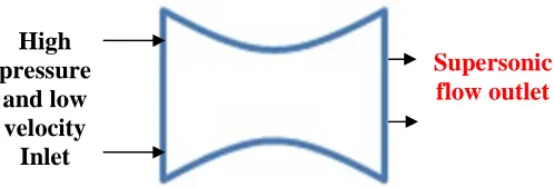
1.1.1 Convergent Nozzle
In this
type of nozzle, cross sectional area is
continuously decreasing. Generally this type of
nozzle used where subsonic speeds are required.
Maximum Mach number obtained by the use of
convergent nozzle is 1.0.
Fig 1.1: Convergent Nozzle Fig 1.2: Convergent – Divergent Nozzle
1.1.2 Convergent – Divergent Nozzle
This nozzle is extension of convergent
nozzle. Divergent portion is added at the end of
convergent section to get the supersonic speeds.
1.2 CFD
CFD is a tool which is used to convert the partial
differential equations into algebraic equations.
With the advancement of computers solving
complex flow problems made easy. Results
obtained by the analysis are more accurate and
also reduces time for solving. Analyzing problems
by using experiments leads to high cost and time
taken is more with the use of analytical
approaches. To overcome these difficulties usage
of software increased in the recent years. It also
determine the nozzle performance effected by
various parameters.
High
pressure
and low
velocity
Inlet
Subsonic
flow outlet
High
pressure
and low
velocity
Inlet
135
2. ANALYSIS OF NOZZLE FLOW
2.1 Theoretical Analysis
2.1.1 Governing equations of fluid flow: 1. Conservation of mass
2. Conservation of momentum 3. Conservation of energy
Conservation of mass
Governing equation of conservation of mass is
Ə
For steady state, 2-dimensional analysis equation can be reduced as follows
Ə( )
Ə +Ə( )Ə = 0
Conservation of momentum
Governing equations of Conservation of momentum are as follows
X- Direction For steady state, 2-dimensional analysis equation can be reduced as follows
Ə(ρu ) For steady state, 2-dimensional analysis equation can be reduced as follows
Ə(ρuv)
Z- Direction
Ə(ρw) For steady state, 2- Dimensional analysis Z- Direction term is eliminated
Conservation of energy
Governing equations of conservation of energy is Ə[ρ% &'(()]
For steady state, 2-dimensional analysis equation can be reduced as follows
Ə[ρ+% &'(()] 2.1.2 Continuity equation
Continuity equation based on the principle of conservation of mass. m = ρAV = constant
Applying logarithm and differentiating equation for steady, one dimensional flow the continuity equation i s 6ρ 2.1.3 Energy equation
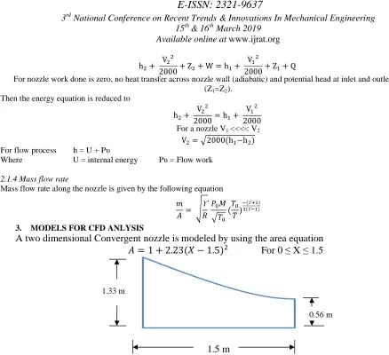
h + 2000 + Z + W = hV =+ 2000 + ZV= =+ Q
For nozzle work done is zero, no heat transfer across nozzle wall (adiabatic) and potential head at inlet and outlet are same (Z1=Z2).
Then the energy equation is reduced to
h + 2000 = hV =+ 2000 V= For a nozzle V1 <<<< V2
V = ?2000(h=−h ) For flow process h = U + Pυ
Where U = internal energy Pυ = Flow work
2.1.4 Mass flow rate
Mass flow rate along the nozzle is given by the following equation
@ A = B
ϒ
C DEF
?GE(
GE
G )
H(ϒIJ) ((ϒHJ)
3. MODELS FOR CFD ANLYSIS
A two dimensional Convergent nozzle is modeled by using the area equation
A = 1 + 2.23(M − 1.5)
For 0 ≤ X ≤ 1.5
Effect of back pressure
Back pressure plays a very important role in the analysis of convergent nozzle. Variation of the back
pressure causes changes in the Pressure, Mach number, density and temperatures in the nozzle. This analysis
is required to know the influence of back pressure on convergent nozzle.
Parameters used for the analysis are,
Mesh size
640 x 15
Residue
1e
-3Pressure inlet
100 kPa, 300 K
Pressure outlet
90 kPa to 10 kPa
Material
Air (Ideal gas)
Fluid
Inviscid
4. RESULTS AND DISCUSSION
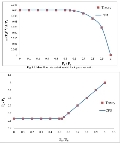
Mass flow rate in the nozzle increases with the decrease of back pressure and attains maximum at critical pressure. Further decrease of pressure will not affect the mass flow rate. Variation of mass flow rate with back pressure resulting from theory and CFD are shown in Figure 5.1. Exit pressure is equal to back pressure up to the critical condition and remains constant below the critical pressure as shown in Figure 5.2.
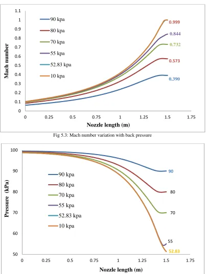
Figure 5.3 represents the Mach number variation through the nozzle. Mach number at the exit of nozzle
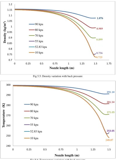
Pressure, density and temperatures decreased with the decrease of back pressure up to the critical pressure and a further decrease of pressure not affected the properties as shown in Figures 5.4, 5.5 & 5.6.
Figures 5.7 & 5.8 clearly show the Mach number and pressures contours along the nozzle at different back pressures. From these contours we can clearly observe the Mach number and pressure variation with back pressure.
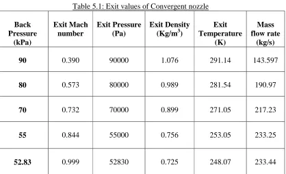
The exit values for different back pressures are shown in table 5.1. A comparison of theoretical and CFD results at critical condition is made in table 5.2 and from this 1.33 m
1.5 m
137 Fig 5.1: Mass flow rate variation with back pressures ratio
Fig 5.2: Exit pressure ratio Variation with back pressure ratio 0
0.005 0.01 0.015 0.02 0.025 0.03 0.035 0.04 0.045
0 0.1 0.2 0.3 0.4 0.5 0.6 0.7 0.8 0.9 1
m
(
T
0)
0
.5
/
A
*
P
0
P
b/ P
0Theory
CFD
0.4 0.5 0.6 0.7 0.8 0.9 1 1.1
0 0.1 0.2 0.3 0.4 0.5 0.6 0.7 0.8 0.9 1 1.1
P
e/
P
0P
b/ P
0Theory
Fig 5.3: Mach number variation with back pressure
Fig 5.4: Pressure variation with back pressure
0.390 0.573
0.732
0.844 0.999
0 0.1 0.2 0.3 0.4 0.5 0.6 0.7 0.8 0.9 1 1.1
0 0.25 0.5 0.75 1 1.25 1.5 1.75
M
ac
h
n
u
m
b
er
Nozzle length (m)
90 kpa
80 kpa
70 kpa
55 kpa
52.83 kpa
10 kpa
90
80
70
55
52.83
50 60 70 80 90 100
0 0.25 0.5 0.75 1 1.25 1.5 1.75
P
re
ss
u
re
(k
P
a)
Nozzle length (m)
90 kpa
80 kpa
70 kpa
55 kpa
52.83 kpa
139 Fig 5.5: Density variation with back pressure
Fig 5.6: Temperature variation with back pressure
1.076
0.989
0.899
0.756
0.725
0.7 0.75 0.8 0.85 0.9 0.95 1 1.05 1.1 1.15 1.2
0 0.25 0.5 0.75 1 1.25 1.5 1.75
D
en
si
ty
(k
g/
m
3
)
Nozzle length (m)
90 kpa
80 kpa
70 kpa
55 kpa
52.83 kpa
10 kpa
291.14
281.54
271.05
253.05
248.07
240 250 260 270 280 290 300
0 0.25 0.5 0.75 1 1.25 1.5
T
em
p
er
at
u
re
(K
)
Nozzle length (m)
90 kpa
80 kpa
70 kpa
55 kpa
52.83 kpa
90 kPa 80 kPa
70 kPa 55 kPa
52.83 kPa 10 kPa
Fig 5.7: Mach number contours with back pressure
Table 5.1: Exit values of Convergent nozzle
Back
Pressure
(kPa)
Exit Mach
number
Exit Pressure
(Pa)
Exit Density
(Kg/m
3)
Exit
Temperature
(K)
Mass
flow rate
(kg/s)
90
0.390
90000
1.076
291.14
143.597
80
0.573
80000
0.989
281.54
190.97
70
0.732
70000
0.899
271.05
217.23
141
10
0.999
52830
0.725
248.07
233.44
Table 5.2: Comparison of CFD and Theoretical values at sonic condition
Variable
CFD
Theory
% Error
Mach number
0.999
1.00
0.075
Pressure
(Pa)
52830
52830
0
Density
(kg/m
3)
0.725
0.734
0.084
Temperature
(K)
248.074
250
0.0872
Mass flow rate
(kg/s)
233.44
233.33
0.0417
5. CONCLUSIONS
1.
For the increase of back pressure Mach
number and Mass flow rate increases
up to some value and constant
although we decrease the back
pressure.
2.
The numerical method adopted (CFD)
predicted the performance of subsonic
nozzle exactly with theory (less than
1% error) and hence CFD tool can be
easily extended for any improvements
or modifications in design.
3.
Values obtained by analysis is nearly
matches with theoretical values.
REFERENCES
1. Madhu B P, Vijaya Raghu B. Numerical Simulation of Supersonic Expansion in Conical and Contour Nozzle. International journal of engineering research & Technology, ISSN-2238-0181, Vol. 3 Isssue 6, June – 2014.
2. Prosun Roy, A bhijit Mondal, Biswanath Barai. CFD Analysis of Rocket engine nozzle. International journal of Engineering Research and Sciences, Vol-3, jan-2016, ISSN: 2349-6495
3. Rabah Haoui. Effect of mesh size on the Viscous Flow parameters of an Axisymmetrc Nozzle. International journal of Mechanical, Aerospace, Industrial, Mechatronic and Manufacturing Engineering VOL: 5, No: 11, 2011.
4. Nadeem N A, Dandotiya D, Najar F A. Modeling & Simulation of Flow Separation & Shocks in a CD Nozzle. International journal of Mechanical Engineering Research & Applications, Vol. 1 Issue 3, August – 2013.
5. 13. John D Anderson, Jr. Computational Fluid Dynamics. McGraw-Hill higher education, ISBN 0-07-001685-2.