-- -- -- --
-
- - - -
SC21·7790·1-
-.--=
:-:a
===
55280..21- - - - -
-~- ..-IBM 5280
Distributed Data
System
- - -
-=--=-=-::.:::
-
SC21 .. 7790 .. 1--
- .---- ----
-
---_
..
---
_.-
S5280-21IBM 5280
Distributed Data
System
Assembler Language Reference Manual
Second Edition (April 1981)
This is a major revision of, and obsoletes, SC21-7790-O and incorporates TNL SN20-9582.
Because the changes and additions are extensive, this publication should be reviewed in its entirety.
Changes are periodically made to the information herein; these changes will be reported in technical newsletters or in new editions of this publication.
Use this publication only for the purposes stated in the Preface.
This material may contain reference to, or information about, IBM products (machines and programs), programming, or services that are not announced in your country. Such references or information must not be construed to mean that IBM intends to announce such I BM products, programming, or services in your country.
Publications are not stocked at the address below. Requests for copies of IBM publications and for technical information about the system should be made to your IBM representative or to the branch office serving your locality.
This reference manual is intended for programmers who want to write programs for the IBM 5280 using the assembler language. The programmer is expected to either have previous experience using an assembler lan-guage or be familiar with the 3741 Application Control
Language (ACL).
Using this publication, the programmer should be able to:
• Understand the general organization of main storage.
• Understand the purpose of each control statement and the proper order for using each control statement in an assembler program.
• Understand the purpose of each instruction and the proper order for using each instruction in an assembler program.
• Write a source program.
• Load the assembler program product into the IBM 5280 system, respond to the assembler prompts, assemble the source program, and write the object program to a diskette.
• Understand the assembly listing and cross reference listing.
• Debug the assembler source program to get an error-free listing.
Chapter 1 contains a general overview of how (1) a source program is written, (2) an object program is executed, and (3) main storage is organized. It also explains the coding conventions used in the assembler language and in this publication.
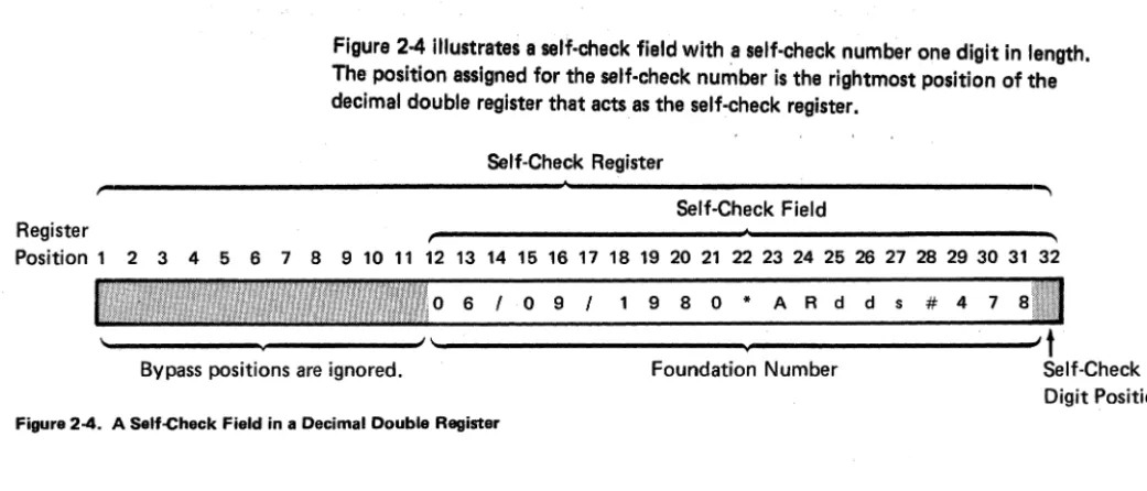
Chapter 2 discusses such programming concepts as tables, subroutines, formats, external status, and self-check compu-tations. It describes data management for input and output operations.
Chapter 3 describes each control statement.
Preface
Chapter 4 describes each instruction.
Chapter 5 explains how to load the assembler program product and how to assemble a source program. It descri bes an assembly listing and cross-reference listing.
Chapter 6 describes control areas and functions. The func-tions include optional common funcfunc-tions.
Chapter 7 explains how to use the ACL to assembler lan-guage conversion program to convert ACL programs.
Appendix A lists the instruction mnemonics in alphabetic order and gives the op code and format for each mnemonic.
Appendix B describes SCS control codes.
Appendix C describes the computations generated by the .SELFCHK control statement parameters.
Appendix D consists of codes and charts, including EBCDIC charts and scan codes.
Appendix E lists all error codes for the assembler program and conversion program.
Related Publications
• IBM 5280 General Information, GA21-9350
• IBM 5280 System Concepts, GA21-9352
• IBM 5280 Functions Reference Manual, GA21-9353
• IBM 5280 Message Manual, GA21-9354
• IBM 3270 Information Display System Component Description, GA27-2749
/ /
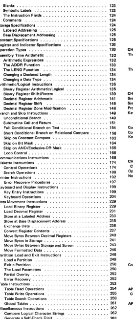
CHAPTER 1. INTRODUCTION • • • • • • • • • • • • • • • • • • • . 1
Overview of the Assembler Language • • . . . • • . . . • • ••• 1
The Control Statements • • • • • • • • • • • . 1 The Instructions • . • • . . . . • • • • • . . . .2
The Source Program Format . . • • . • • • . .2
The Assembler Program . . . .3
Loading the Object Code . • . • • • •. . . . . • . . . •• 3
Overview of Program Execution . . . • . . • • • . • . . . . .3
Overlapped I/O • . . • • . . • . • . •. . • . . . • • • • . . . 4
External Status .. . . . 4
Data Input • . . . • . . • . • . • • . • . . • . . . • . . . . 4
Data Manipulation . . • . . • • . . • . . . • . . • . . . . • • . • . 4
Data Output • • • • . • . . • • • • • • . . • • • . . . • • . . 5
Overview of Main Storage . . . • . • . . . • . 5
Logical Device Identifiers • . . • . . . • . • • . . • . • . • • • . . 6
Common Functions . . . • • . . • . . . • • . . . • • . • . . 6
Partitions . . . • . . . • . . . • • . . . . . . 6
Modes of Operation . . . . . . : • . . . . . . ' . . . . • . . 6
Partition Control Area • . . • • . . • . . . • . • • . . . 8
Indicators and Registers . • . • . • . . . 8
Storage . • • . . . . • . . . . . 11
Addressing Methods . • . • • . . . • • 11
Partition Work Area • • . . . . • • . . 12
Main Storage Boundary Alignment • • . • • . . . . 13
Blanks, Constants, and Coding Symbols . • • • . . . 14
Symbols Used in This Manual . . . • • . . • • . • . 15
CHAPTER 2. PROGRAMMING CONCEPTS . . . • . 17
Tables . . . • . • . . . • • . . • . . . • . . . 17
System Tables . • . . • . . . • . • • • • • • . . • . . . 17
Data Tables. . . . . . • . . • • • • . . • . . . 18
Label Tables . . . . . • . . . . • . . . 18
Data Types • . . • . • • . • . • • . . . 19
Subroutines. . . • . 19
The Partition Subroutine Stack •. . . • . • . 20
Subroutine Returns . . . • • • . . . . . 20
The Status line . . . • . . . • . . • . . • . 22
Nondisplay of the Status line • • • . . . 23
External Status and Error Conditions . . . • • . . . • . • 24
Keyboard Data Entry' . . . • . . • • . . . . • . . 25
Keystroke Buffering . . • • . . . . • . • . . . • . . . 26
Modes of Entry . • . . . • . • . • . • • • • • • . 26
Automatic Functions •.• • . . . • . . • • • . • • • • . • • . . 28
Auto Enter . . . • . • • • . . . • • • . . • . . . 29
Auto Duplicate/Skip . . . • . . . • • • • . 29
Alternate Record Advance • • • • • . . . • . . • . . . 29
Screen Formats . . . . . • • • • . . • • • . • • • • . • 29
Prompts • • • . . . • . . . . • • • . • . . . • . • . • . 30
Constant Insert Data • • • • . • • • . . . • • • . . • . . . • 31
Field Definitions. • . • . • • • . . • .. .. 31
Field Control . . . • • . . . .. •• 32
Returning IRG) Exits . . . • . . . . .. .• 34
Edit Formats • . • • • • . • . . . .. •• 34
Data Directed Formatting . . . • . 35
Field Modification Indicators • • • . . • . . . • • . • 35
Diskette Data Management . . . . Label Update • • • • . • • . • • • • • Physical and Logical Buffers Automatic Logical Buffering . • . • . . . 36
· . . . 36
· . . . 36
· . . . 36
Contents
Pointer I/O . • . . . • . . . . • . . . • . • • . . . • . . • 37Keyed Data Sets . . . • . . . • . . , . . . • 38
Shared Data Sets • . . . • • • . • • . . . . • • • . . . • • • • • • 40
SCS Conversion Data Sets • • • • • • • . • . . . • . . . • • . 40
Extending Data Sets . • • . . . • . . . . • . . . . • . . • • • . • 40
Self-Check . . . • . . . • . • • • • • . . . . . . • • • . . • 41
Choosing Your Algorithm . . . • . • • .44
Using the GSCK Instruction .•• . . . • .47
Using the IF ... CHK Instruction . . .47
CHAPTER 3. ASSEMBLER LANGUAGE CONTROL STATEMENTS • • • • • • • • • • • • • • • • • • • • • • • • • • • • 49 Format . . . . . . . • . • . . . . . • 51
Blanks • . . . • • • • . . . • . • • • • • . • . • . . . • • . • • 51
Comments ' • • . • • . . . • • • . . • . . • . • • . . . 51
Initialize the Partition Control Area • . . . • . . . • . . . 52
.ST ART Control Statement . . . . • • • . 52
.KBCRT Control Statement . . . . • . • . . . . • . 53
.EDITC Control Statement . . . . • . • . • . . . 56
Declare and Label Data Areas . • • . . . . • • .. .. 57
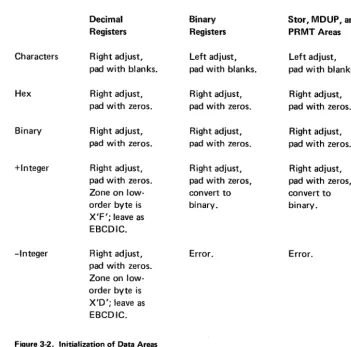
.DC Control Statement . . • . . . • • . • .DCLBR Control Statement .DCLDR Control Statement •.. · .57 · .65 · .65 .DCLIND Control Statement • . . . • . . . • . • . . .EQUATE Control Statement . . . • . • . . . • . . . . · .65 • .66 Set Up and Initialize Device Control Blocks .. .COMM Control Statement . . • . · .69 .. .. 69
.DATASET Control Statement .. Set Up arid Label Tables . . . • • .TABLE Control Statement .LABTAB Control Statement .SYSTAB Control Statement . . . Set Up Edit Formats' . • . . . • . . . .FMTST Control Statement . . . 72
· .79 · . . . • . . • • . . . . 79
· . . . . • . . . . . • 81
. . • • • . . . • • . 82
· . . . .84
. . . • • • • . . • • 85
.FMTFLD Control Statement •• . . . . . • • . . . • 85
.FMTEND Control Statement .. . . . . . • • • . • . 92
Set Up Screen Control Formats . . . • • • . . . • 92
.SFMTST Control Statement • . • . . . • . . • . . . • . • . . . 97
.SFMTCTL Control Statement . . . . . . 98
.SFMTPMT Control Statement • . . . '\. . 100
.SFMTCNS Control Statement . .SFMTFLD Control Statement .. .SFMTEND Control Statement Field Type Keywords • • . • . . . Field Definition Keywords Control the Assembly listing .TlTLE Control Statement .EJECT Control Statement 102 103 106 107 109 113 113 114 .SPACE Control Statement 114 .PRINTON Control Statement . . . • • . . . 115
.PRINTOFF Control Statement . . . • . . . . • . • • 115
Miscellaneous Control . • . . . . • . • • . . . • . . 115
.INCLUDE Control Statement . • . • . . . • • • . • . 116
.SELFCHK Control Statement • . . . • • . . . 116
.XTRN Control Statement • . . . • • • • . • • • . • • . • . . 120
.END Control Statement . . • . • • . . . 121
CHAPTER 4. IBM 5280 ASSEMBLER LANGUAGE INSTRUCTIONS • • • • • • • • • • • • • • • • • • • • • • • • • • 123 Instructions Format . . • . • • . . • . . . • • • • • . • • . . • • . 123
Blanks . . . • • • . • . • • . . • • . . . • 123
Symbolic Labels . : . . ; . . . • • • . • . • • • . • • . . . •. 123
The Instruction Fields • . • . . . • . • . • 124
Comments . . . • . • • • • • . • • . . • . . . 124
Storage Specifications . • . • • • • . • • • • • . . . • . . • •• 124
Labeled Addrenlng • . . • • • • • . • . • . • • • • • . . • • • 126
Bale [)leplacement Addre •• lng • • . • • . . • • . • • . . • •• 126
Conetant Specifications . . • • . . . • • . • • •• . • . . • .• 126
Register end Indleetor Specifications • . • . • . • . • . . . • . . 126
Operation Types . • . • • . • • • . . . • . • . • . • • • • . . • . . 126
All8mbly Time Arithmetic • . • . . • . . • . • . . . • . • • . 132
Arithmetic Expres.lons . . . • • . • . • • • •• " . • • • • •• 132 The AD DR Function . • • . • • • • • • • . • . . • • . • • . . 133
The LENG Function . . • . . • • • • • • . • • • . • . . • • • 134
Changing a Declared Llmgth .• "." • . . • • • . . . . • • • 134
Changing' Date Type . . . • . . . • • • . . . 134
Arithmetic/Logleal Instruction. . . . • • . • . • . . . • . • • • . 136
Binary Regl.tar Arlthmetlc/Logle,1 . . . • . . . 136
Binary Register Shift/Rotate . . . . • • . . • . . . . • . • .• 139
Decimal Raglster Arithmetic . • . . . . • . • . • • • . . • . . 141
Declmel Regieter Shift . • • • • • . . . • • • • • . . . . • . • 146
Decimal Register Zone Modification . . . . • • • . • . . . . 148
Brench and Skip Instructions . . . . • . . . • . . . • . 149
Unconditional Branch • • . . . • • • . . 149
Subroutine Call end Return . . . • . • . . • • . . . 161
Full Conditional Branch on Test . . . • . • • . • 164
Short Conditional Branch on Relational Compare • . . • . . 168
Skip on Constant Compare . . . • . . . • . • . . . 162
Skip on Bit Mask . . . . • . . . • . . . • . . . . 164
Skip on AND/Exclusive-OR Mask . . . 166
Loop Control . . . . '166
Communications Instructions . . . , . . . 168
Diskette Instructions . . . 174
Control Operations . . . 174
Seerch Operetlons • . . . . 188
Printer Instructions . . . 192
Error Recovery Procedures . . . . 197
Keyboard and Display Instructions . . . 199
Key Entry Instructions . . . 199
Keyboard Operations . . . 204
Data Movement Instructions . . . . 229
Load Binary Register . . . 229
Load Decimal Register . . . 231
Store at a Labeled Address . . . . 233
Store at Base Displacement Address . . . 235
Exchange Data . . . . . . , , , , , , , . , , . . . , , , . 236
Convert Register Contents . ' . . . 237
Move Bytes Between Decimal Registers . . . . 240
Move Bytes in Storage . . . . 241
Move Bytes Between Storage and Screen . . . 243
Move Formatted Data . . . . 246
Partition Load and Exit Instructions . . . 248
Load a Partition . . . 249
Exit a Partition . . . . . . , . . . . 250
The Load Parameters . . . 250
Partial Overlay . . . . 252
Error Recovery . . . . 252
Table Instructions . . . 253
[image:7.612.49.321.44.697.2]Table Read Operations . . . 254
Table Write Operations . . . 255
Table Search Operations . . . 258
Global Tables . . . 261
Miscellaneous Instructions . . . 262
Compare Logical Character Strings . . . 262
Generate a Self-Check Digit . . . 263
Modification for Indirect Instruction Execution • • • • • . . 263
Duplicate a Byte in Storage • . . • • • . • • . • • • • • • • •• 266
Search Resource Allocation Table . . • • • . . . • . . . . 266
Set Bits with Mask • • • . • . • • • • • • • • . . . • : • • . . . 266
Set Indicators • • . . • • • • . • . • • • • • . . . • . • • • . . 266
Exclusive-OR Write, Skip on AND Ma.k . . . • • • • • 267
System Lock and Unlock . . . . • • • . . • • • • • . • . • • • 268
Tran.latlon • . . • . • • • . . . • • . • • . • • . • • • • • • 268
CHAPTER IS. HOW TO ASSEMBLE YOUR PROGRAM •••• 271 The IBM 6280 Aallmbler • • . • • • • • • • • • • • • • • . • . . 271
Loldlnll the Anambler Into a Partition . • • . • • • • • • . • 272 The A ... mbler Prompt. • . • • . • • • . • . • . • • • • • • • • 272 The Aallmbler Llltlnll • • . • . , •••••.•••••••.•.•.• 278 A Printed A •• embly Llltlnll ••••••. " . • . • • . . • . • • 278
The Crosl·Reference Lilting • • • . • • • . • • • • . . • • • . 280
Error Mellllll81 . • • • • • • • • • • • • . " •••.••••••• 281 CHAPT!F". CONTROL AREAS ••••••••••••••••• 283 System Indlc.tora within a Partition . . . • . • • • . • • 283
SYltem Regl't.ra within a Pertltlon . . • . . • • . • • . . . • • • 284
Program Check Errore . • • • . . • . • • . . . • . . • • • . • 286
Keystroke Counters . . • • • . . . • . • . • . . • . • . . • • . . • 286
Dati Entry K.ystroke Counter • . • . . . • • . . . . • • . • . 286
Verify Correction Key.troke Counter . . . • . . . • . . . 286
Common Function Routln.. . . . . 286
Common Function Error Routln . . . 288
Keyboard/Display External StatuI . • . . . • • • . . . .. 302
Restricted External Status Indicator . . . • . • • . . .• 304
Extarnal Status Subroutines . . . • . • . • . . • • . . . • 304
External StatuI Conditions . . . • . . . .. 306
CHAPTER 7. THE ACL TO ASSEMBLER LANGUAGE CONVERSION PROGRAM . • • • • • • • • • • • . • • . • . . • 317
Operation . . . 317
Notes About the Converted Program . . . 320
The Format of the Converted Program . . . 320
Labels and Sequence Numbers . . . 320
The Format of the Display Screen . . . .. 321
Buffers . . . 323
The .FORMAT Control Statement . . . 325
Indexed Branch Instructions . . . 325
The OPEN Instructions . . . 325
The ENTR Instructions . . . 325
The EXEC Instruction . . . 326
Keyed Data Sets. . . .. . . . 326
The ACL Deleted Record Subroutine . . . 326
Physical Buffers. . . . 326
Print Instructions . . . 327
Leading Blanks . . . 327
Function Keys . . . 327
The Minus Key . . . . 327
ACL Toggle Switches . . . 329
Conversion Chart . . . 329
Control Statements . . . 330
Instructions . . . 331
Indicator Conversion . . . .. 334
APPENDIX A. MNEMONIC TO OPERATION CODE CONVERSION CHART AND INSTRUCTIONS FORMAT . . 337
APPENDIX B.
ses
CONTROL CHARACTERS • . . . • • . . • 343Function Types Available for Use with the Format (Fmtl Printer Control Character . . . 345
[image:7.612.312.560.45.632.2]APPENDIX C. SELFoCHECK COMPUTATIONS •••••••• 361
APPENDIX D. KEYBOARD CODES AND EBCDIC
CHARTS • • • • • • • • • • • • • • • • • • • • • • • • • • • • • • 369
EBCDIC Charts for Printable Characters • • • • • • • • • • • • • 369
Keyboard Functions: EBCDIC Codes and Bit Numbers •..•• 371
IBM 5280 Mode Keyboard Functions • • • . . • • • • • . . • • • 371 IBM 3270 Mode Keyboard Functions • • • • • • • • • • • • • • • 375
APPENDIX E. ERROR MESSAGES • • • • • • • • • • • • • • • 377
Auemblar Erron and Mesugel • • • • • • • • • • • • • • • • • • • 377
Conversion Program Erron • • . • . • • • • • • . • • • • • • • • • 379
APPENDIX F.SAMPLE PROGRAM • • • • • • • • • • • • • • • 381
GLOSSARY. . • • • • , ~ . I • • '" I • • • • , I It • • , " • • • 387
INDEX ."., •.• I • , • • • • " • • " • • • " • • • • • • II • • II 388
Chapter 1. Introduction
The IBM 5280 is a diskette-based data entry system with partitioned main storage. It consists of keyboard/display data stations with optional diskette drives, a com-munications line, and printers. The IBM 5280 operates with multiple tasks, each run-ning in a main storage partition. It can be used in data entry, remote batch, remote inquiry, or preprocessing environments. Input source records can be edited, veri-fied, and placed into main storage registers, tables, or other data areas. In main storage, the records can be manipulated with arithmetic and logical operations. The records can then be reformatted and written to a data set. (A data set is a group of records stored on a diskette.) The data sets on the diskettes can then be used as input to a data processing system.
The data stations and I/O (input/output) devices are described in the General Information manual. You should be familiar with these units before you begin pro-gramming in the IBM 5280 assembler language. You must also be familiar with the organization of main storage, which is described in this chapter. Preceding the overview of main storage, this chapter gives overviews of the assembler language and of program execution. These overviews briefly describe the format of the source statements, the generation of the object code, how the IBM 5280 executes the object code instructions, and the major functions the object code can perform.
OVERVIEW OF THE ASSEMBLER LANGUAGE
The IBM 5280 assembler language consists of control statements and instructions. The control statements define the main storage control and data areas. The
instruc-tions specify the operainstruc-tions and operands. No job control language is necessary for the IBM 5280.
The Control Statements
In your source program, a control statement is always preceded by a period (.). Control statement parameters are written with uppercase letters. The control statements are described in Chapter 3, where they are organized by function:
• Initialize control areas and I/O control blocks (lOBs)
• Declare and label data areas
• Organize tables
• Set up screen formats
• Set up edit formats
• Control the assembly listing
The Instructions
In your source program, the instructions specify the operations and the operands. Operations are specified by arithmetic symbols or by uppercase mnemonics. Oper-ands are specified as immediate data or as the contents of a data area. Data areas are referred to by a label or by a base displacement address. The instructions are described in Chapter 4, where they are organized by the types of operatiOn they perform. The operations include:
• Arithmetic/logical
• Branch and subroutine
• Communications input and output
• Input and output to diskette or printer
• Input and output to keyboard/display
• Data movement
• Partition load and exit
• Table read, write, and search
• Miscellaneous
The Source Program Format
Source statements are written with a length of 72 positions per line. Parameters are separated with spaces. You may space freely between parameters, but spaces are not allowed between a parameter and a parameter value .. A control statement may be written on one or more lines. An instruction, however, must be complete within the first 72 positions of a line. Comments may be written on a control state· ment or instruction line, or an entire line may be written as a comment line.
Certain control statements must be written in a prescribed order. This order is explained in Figure 3-1, Control Statement Summary in Chapter 3.
The Assembler Program
The IBM 5280 assembler program reads the source program from the diskette-and uses it to generate ~he object code. It detects syntax errors in the source control statements and instructions. It converts each label and base displacement address to an address relative to the beginning of the partition. It converts each series of screen format control statements to a string of object code, which is referred to as a screen format control string. From each source Instruction, it generates a 4-byte object code Instruction; the first byte always contains the operation code that determines the operation, and the other
3
bytes contain the operands. An operand may be Immediate data, a format number, a table Index, or the address of data tobe operated upon. When the assembler program hal converted the source program
to object code, It then writes the object code to a diskette data set. It also gener-ates an al8embly listing that can include:
• Source code and object code
• Syntax error messages
• Storage allocation messages
• Alphabetic cross-reference of symbols used in the source program
The assembly listing can be written to a printer or to a diskette data set. Chapter
5
describes how to load and execute the assembler program.
Loading the Object Code
The object code data set that is written by the assembler program must be loaded into a main storage partition for execution. The object code for a program can be loaded into any partition that is of sufficient size. An operator may load the object code by responding to a load prompt. Or a program being executed in a partition can have instructions to load another object program into another partition or into the same partition. See
Partition Load and Exit Instructions
in Chapter 4 for more information about loading the object code.OVERVIEW OF PROGRAM EXECUTION
When the object data set is loaded into main storage partition, control informa-tion and address pointers are stored in a partiinforma-tion control area. This control infor-mation is used by the IBM 5280 and the I/O devices during program execution. The control information is followed (1) by the data areas specified in the source pro-gram control statements and (2) by the 4-byte object code instructions.
The IBM 5280 executes the object code instructions sequentially until a specified time limit is expired or until an I/O instruction is encountered. When the time limit expires, the IBM 5280 suspends processing in that partition. The IBM 5280 then enters the next partition that has been loaded with an object data set and begins executing instructions in that partition.
If an I/O instruction is encountered, the IBM 5280 determines which I/O device is to process the operation. It places control information into the partition control area and issues the I/O instruction to the device. The I/O device processes the I/O operation, using the control information in the partition control area and in the
lOB that describes that I/O operation.
Overlapped I/O
Certain instructions may specify overlapped I/O. (The instruction descriptions in Chapter 4 indicate when overlapped I/O may be specified.) When the IBM 5280 encounters an I/O instruction that requests overlapped I/O, it issues the instruction to the appropriate I/O device. The IBM 5280 then either: (1) remains in the current partition and executes the instruction fol/owihg the I/O instruction, or (2) if the time limit has expired for the current partition, exits the current partition and executes instructions in the next partition that contains an object data set. The
I/O device processes the I/O operation concurrently with the sequential instruction execution.
If overlapped I/O is not specified, the IBM 5280· issues the I/O instruction to the I/O device and exits the partition. The instruction following the I/O instruction is not· executed until the I/O instruction is completed by the device.
External Status
While an I/O device is processing an I/O operation, it may encounter an external status condition that requires operator intervention or processing by the IBM 5280 control/er. A four-digit condition code is placed into the lOB; it may also be dis-played on the status line. These condition codes are described in Chapter 2 under
External Status and Error Conditions.
Data Input
For input via the keyboard/display, the screen format (which you specify with control statements) determines the promP,ts that are displayed on the screen and the display attributes for the screen, such as blink or underscore. The screen format can specify which characters are valid for each individual field of the input record. Valid fields of the input record are stored in an I/O buffer.
For input from a diskette data set, a program instruction can direct the IBM 5280 to read a data set record. The records in a data set can be accessed sequentially, directly by relative record number, or directly by key. The input record is stored
in the I/O buffer.
Data Manipulation
Data Output
Your program instructions and formats also control record output. Records can be moved from main storage data areas to an I/O buffer. An edit format can reformat the record and insert punctuation. The records can then be written to a display, a diskette data set, a printer, or the communications line.
OVERVIEW OF MAIN STORAGE
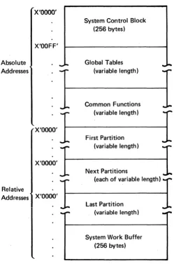
Main storage is organized into areas for system control, tables, common functions, partitions, and a system work buffer, as illustrated in Figure 1-1.
X'OOOO'
X'OOFF'
Absolute
_
..
Addresses
X'OOOO'
Relative
Addresses X'OOOO'
System Control Block (256 bytes)
Global Tables (variable length)
Common Functions (variable length)
First Partition
(va,'ab'.'.ngth)
I
Next Partitions
~
(each of variable length)
Last Partition (variable length)
[image:14.613.158.408.201.585.2]System Work Buffer (256 bytes)
...
Figure 1-1. The Organization of Main Storage
The system control block is located in the first 256 bytes of main storage.
The fields of the system control block have fixed locations. However, all partitions, and all storage locations within a partition, are accessed by pointers. The pointers,
which are set up and maintained by the IBM 5280, are located in the fixed locations of the system control block. These pointers make it possible for each of your assembler source programs to address locations as they relate to the partition, rather than as they relate to main storage as a whole. These relative addresses remain valid for any partition into which your program is loaded.
Logical Device Identifiers
Logical device identifiers are tWo-character IDs that allow you to symbolically ad-dress a resource independently of machine or partition configuration. The logical device IDs are stored in a resource allocation table, which is created and loaded into the global tables area by the system configuration portion of the SCP (system Control Program). The resource allocation table specifies the logical devices that can
be accessed by each partition. Each resource allocation table entry contains both the logical device 10 and the phYsical address of that device; Whenever a program instruction requires a device address, you can specify the two-character 10. The IBM 5280 searches the resource allocation table for the physical address of the device with the matching 10. The IBM 5280 uses the device at that physical address to access the data set that is available to that device.
The logical device IDs are used only in program instructions. Do not enter a logical device 10 via the keyboard in response to a prompt that requests a physical address.
Common Functions
The common functions area contains IBM-supplied global subroutines. They can be accessed by a subroutine call from any partition. The labels and functions of these subroutines are listed in Chapter 6 under Common Function Routines.
PARTITIONS
There. may be up to eight partitions numbered sequentially from zero. There must be at least one partition for each keyboard .. A partition is of variable length, but it cannot cross a 64 K byte boundary. The number, size, and location of the parti-tions is. defined at system configuration time. The first 256 bytes of each partition contains control information in fixed locations from the beginning of the partition. The next 3840 bytes may be used as needed for indicators, decimal registers, binary registers, or storage areas. This area is followed by a variable-length stprage area. The last 256 bytes of each partition is used for a work area. Each byte of a parti-tion is addressable relative to the first byte of the partiparti-tion. Figure 1-2 shows the different areas of a main storage partition.
Modes of Operation
:;
...
8.
c:: (")...
o·
::> -.J "TI ~. Cil -~Cil -t
-':3"
!!I. CD
C' 0 CD ..
.. u::a
e,.!l e,. _.
Cil III
• g'
; a
..
..
.. :=:
....
if
:i"
.!
~
!l
i
e,.CD..
~':3" ..
CD ~
a'
a:
c:: 0
.. ::I
....
':3"
e,.-t
'2:
...
ifiii" [
a ...
. . ':3"
Ii
ill:
'i"
Relative Addresses X'IIII'ILo
000 OOF 010-. BRO
1
1000-1015
011 BR8
.1.
1128-1143 012 BR16:~
01F BR120
020
021
:
...
OFE
a
OFF...
2 3 4 5
BRl BR2
1016·1031 1032-1047
BR9
1
1144-1159
BR1°l 1160-1175
BR17 BR18
BR121 BR122
6 7 8 9 A B C 0 E F
+tlOOJo""+
BR31 BR4
J.
BR5 BR6 BR71048-1063 1064-1079 1080-1095 1096-1111 1112-1127
BR11
1
BR12J
BR13J.
BR 14.1
BR151
1176-1191 1192-1207 1208-1223 1224-1239 1240-1254
RO}
Rl
BR19 BR20 BR21 BR22 BR23
R2
:
BR123' BR124 BR125 BR126 BR127 R15
R16
R17
-R238
if __
I
I
R239if 100
t
l¥3'
!!.....
-r' - - - - -'--
J
-
-Storage Area
Work Buffer
- '---
I
Partition Control Area
The partition control area contains control information that describes the program that is loaded into the partition and defines the I/O devices used in the program. The IBM 5280 loads this information into fixed locations within the control area, using information from the common area and from the source program control state-ments. During program execution, the IBM 5280 uses this control information each time it enters the partition to determine the partition status, the I/O status of the program, and the address of the next executable instruction.
Indicators and Registers
Immediately following the partition control area is an area that may be used for indicators, binary registers, and decimal registers. These bytes may be used in any desired combination of indicators and registers as described in the following para-graphs: if some of these bytes are not used for their binary register/decimal register capabilities, the unused bytes may be used as storage. Figure 1-2 shows the bytes that may be used for indicators and registers.
Indicators
The first 32 bytes of this area contain 255 one-bit indicators. In your source pro-gram, the indicators can be represented by the letter I and the indicator number. They are numbered sequentially from 10 to 1254. The first 100 indicators 00-199)
may be labeled, set, tested, and reset as your source program dictates. These indi-cators are referred to as program indiindi-cators. The remaining indiindi-cators (1100-1254)
are set and maintained by the IBM 5280, and are referred to as system indicators. System indicators have specific meanings assigned to them, as described in Chapter 6 under System Indicators Within a Partition.
You can label program indicators with a .DCUND control statement. When the assembler processes the .DCLIND control statement, it assigns each specified label to an available program indicator.
You can label system indicators with an .EQUATE control statement. The
.EQUATE control statement allows you to specify the number of the indicator you want assigned to each label. You could use the .EQUATE statement to label pro-gram indicators also; however, you usually don't care which propro-gram indicator is assigned to each label.
Two instructions are available to test indicators. The IFI instruction can test the indicator and perform a conditional branch. The IFIR instruction tests the indicator and performs a conditional branch, but it also resets the indicator to O. Your pro-gram can use these instructions to test propro-gram or system indicators.
You can use the instruction SON to set an indicator (1), or the instruction SOFF to reset an indicator (0). See Set Indicators under Miscellaneous Instructions in Chapter 4 for a description of these instructions.
Binary Registers
The first 256 bytes of this area may be used for up to 128 two-byte binary registers_ Binary registers can be represented by the letters 'BR' or '8' followed by the register number. The registers are numbered sequentially from BRO to BR127. BRO-BR15 are used as indicators (as described in the preceding paragraphs). and BR16-BR31 are used as system registers. The system registers are used and maintained by the IBM 5280 during program execution and hold information as described in Chapter 6
under System Registers Within a Partition. You should not assign these registers
to any other purpose. The system registers should always be reserved (see the RGL T parameter of the .START control statement). In your source program you can access the reserved registers by register number, or you can use the .EQUATE control statement to assign them labels.
The binary registers that are not reserved by the RGL T parameter of the .START control statement can be labeled and initialized by declare control statements in your source program. Use the .DC control statement to label and initialize one binary register, or the .DCLBR control statement ta+abel several uninitialized binary registers.
Although binary registers are 2 bytes in length, you can access either 1 or 4 bytes by defining the byte length, in parentheses, follo'!ving the register number or label.
If you specify a length of 1 byte (BR40(1)). only the rightmost byte of 8R40 is
accessed. If you specify a length of 4 bytes (BR40(4)), the 2 bytes of BR40 and the 2 bytes of BR41 are accessed. A binary register specification with a length of 4 bytes is referred to as a binary double register.
Binary registers are often used to hold addresses. The instructions to load a binary
register are described in Load Binary Register under Data Movement Instructions in
Chapter 4. In your source program, you can load a 2·byte binary register with:
• An unsigned decimal integer (0-65535)
• Two EBCDIC characters
Figure 1·3 shows the hex representation of binary data in two binary registers.
High-
Low-Order Order
Byte Byte
---.. ---..
BR75 F 0 1 A
I
BR76 C D 0 F
Figure 1-3. Binary Registers
The following examples illustrate the different ways you can refer to BR75 if you assign it the label BREG1.
BR75 BR75(2) BREG1 BREG1(2)
BREG1(1) BR75(1)
BR75(4) BREG1(4)
Decimal Registers
}
}
}
specifies the full 2-byte binary register, which contains hexadecimal F01A.
specifies the low-order byte of BR75, which contains hexadecimal 1 A.
specifies the 4 bytes of BR75 and BR76, which contain hexadecimal F01ACDOF.
The 3840 bytes of this area may be used for up to 240 sixteen-byte decimal registers. Decimal registers can be represented by the letter R and the register number. The registers are numbered sequentially from RO to R239. The bytes within RO and R1 are used for indicators; the bytes within R2 and R3 are used for system registers. You should not assign RO-R3 for any other purpose. In your source program, the decimal registers reserved by the RGL T parameter of the .sTART control statement can be accessed by registe~ number. Or you can use the .EQUATE control statement to assign them labels.
Decimal registers not reserved by the RGL
T
parameter of the .START control statement can be labeled and initialized by the declare control statements in your source program. Use the .DC control statement to label and initialize one decimal register, or the .DCLDR control statement to label several uninitialized decimal registers.Although a decimal register is 16 bytes in length, a double decimal register of 32 bytes may be specified by defining the byte length in parentheses, following the register number or label. Decimal registers and double decimal registers are valid in decimal arithmetic and shift operations, branch operations, and table operations. All data in decimal registers is stored in EBCDIC notation. The instructions to load a decimal register are in Load Decimal Register under Data MOVlJment Instruc-tions in Chapter 4. In your source program, you can load a 16·byte decimal register with:
• A positive or negative decimal number (±O to 1016 -1)
• Up to 16 EBCDIC characters
The following examples illustrate the different ways that you can refer to R120 if you assign it the label REGX.
R120 }' REGX
R120(32) } REGX(32)
specifies the 16 bytes of R120.
The contents of a decimal register may be positive or negative; the sign is deter-mined by the zone half of the byte in the units position (byte 15) of the decimal register. If the register contains a positive number, hex F is in the zone half; if it contains a negative number, hex D is in the zone half. Figure 1-4 illustrates the sign control position in a decimal register.
Sign Control Position
Byte Zone Digit
Q
o
1 2 3 4 5 6 7 8 9 10 .11 12 13 14 15I· ...
J .. "
-I- ...
·1· ...
+
....
f ....
I· ...
-I- ....
f ....
j ...
f ....
f ....
j. ...
·1· ...
f· ....
'lir:~I!~:!~:1
Figure 1-4. The Sign Control Position in a Decimal Register
The zone halves of the bytes are used for sign control; however, no checking is done by the IBM 5280 to determine whether the register contents are numeric or alpha-betic.
Storage.
Following the registers is a variable-length area of storage. The size of this area is the size of the partition, less the 256 bytes of the partition control area and the bytes used for indicators and registers. The instruction object code is stored in this area, with the buffers, tables, formats, messages, device lOBs, control tables, data, and data structures necessary for the program.
Addressing Methods
In your source program, each byte of storage within a partition can be addressed directly, using an assigned label, or indirectly, using a displacement and a base address.
Direct labeled addressing of a storage location is accomplished by using a declare control statement to assign a label to a storage area of any length. To access this labeled area in a source program instruction, the following format is used.
label [(length)]
where:
label is the assigned label from the declare control statement. The label addresses the leftmost byte of the storage area.
length is the length, in bytes, of the storage area. If length is not specified in
the instruction, the length defaults to the length assigned to that area by the declare statement.
Indirect base displacement addressing of a storage location is accomplished by
specifying in the instruction (1) the location of the base addres and (2) the dis-placement from that base address at which the storage area is located. The length may be specified for many, but not all, instructions. To access a storage location by indirect addressing, one of the following formats is used.
[displacement] ([length], BRn) [displacement] (BRn)
where:
displacement is the number of bytes (0-255) from the base address at which the
storage area is located. If the displacement is not specified, it defaults to O.
length is the length, in bytes, of the storage area. The instruction descriptions
indicate whether or not length is allowed in the address. If a length specification is allowed, it must be followed by a comma. If length is omitted from an instruc-tion that allows a length specificainstruc-tion, the comma must be retained. If the instruction does not allow a length specification, the comma must not be
included in the address.
BRn is a binary register that contains the base address. The base address is rela-tive to the start of the partition.
When a source program instruction that.has an indirect storage address is assembled, the displacement is added to the base address in the binary register. The result is the relative address of the leftmost byte of the data area. This address is placed in the object code.
Examples:
Direct: BIN1 = STOR1(2)
The contents of the byte at STOR1 and the next byte (length is 2) are loaded into the binary register labeled BIN1.
Indirect: BIN2 = 1 (2, BREG)
The displacement of 1 is added to the address stored in the binary register labeled BREG. The contents of the byte at the resulting address and the contents of the next byte (length is 2) are loaded into the binary register labeled BIN2.
Partition Work Area
000- OOF-
010-
011-
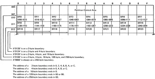
012-MAIN STORAGE BOUNDARY ALIGNMENT
o
BRO 1000-1015
BRB
.l
112B-1143 BR16
-
IMain storage is divided by several types of boundaries. Each type of boundary encloses an area of a specific number of bytes. Many data areas must begin on a certain type of boundary. Figure 1-5 represents a main storage partition and points out the different types of boundaries. The system configuration portion of the SCP begins each partition on a 256-byte boundary and measures the length of each partition in multiples of 256 bytes.
2 3 4 5 6 7 8 9 A B
c
op~rtition
CLtrol A+BRl BR2 BR3
.!
BR4J,
BR5 BR61016-1031 . 1032-1047 104B-1063 1064-1079 IOBO-1095 1096-1111
BR9
1.
1144-1159
BR1°l 1160-1175
BR 11
.!
1176-1191
BR12
J.
1192-1207
BR13
J.
120B-1223
BR14
.1
1224-1239
BR17 BR1B BR19
I
BR20J
BR21 BR22I I I I I I
L.... X'0126' is on a 2-byte boundary.
- X'0124' is on a 2-byte and 4-byte boundary.
- X'0120' is on a 2-byte, 4-byte, and 16-byte boundary.
' - - - - X'0100' is on a 2-byte, 4-byte, 16-byte, 12B-byte, and 256-byte boundary. X'OOOO' is alwa s on a 256-b te boundar . y y y
The address of a 2-byte boundary ends in 0, 2, 4, 6, B, A, or C.
The address of a 4-byte boundary ends in 0,4, B, or C.
The address of a 16-byte boundary ends in O. The address of a 12B-byte boundary ends in 00 or BO. The address of a 256-byte boundary ends in 00.
Figure 1-5. Main Storage Boundaries
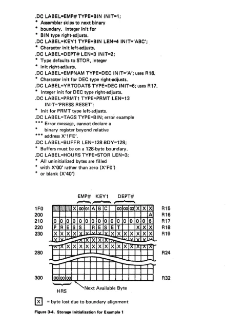
When you declare a register in your source program, the assembler places it on the next sequential boundary appropriate for the type; it places a binary register on a 2-byte boundary and a decimal register on a 16-byte boundary. It places all other data types on 1-byte boundaries unless you specify a boundary. When you are build-ing a storage structure, you may want to specify a boundary. When the IBM 5280 assembler processes your source control statements and sets up these data areas, it skips over any storage bytes between the current location and the next appropriate boundary in order to observe the boundary restrictions. These bytes cannot be used by your program. Your assembly listing indicates how many storage bytes are lost due to boundary alignment. See the examples following the description of the .DC control statement in Chapter 3 for an illustration of boundary alignment.
E F
BR7
1112-1127 RO
BR15
.!
1240-1254 Rl
BR23
R2
I ~""
[image:22.617.64.569.156.412.2]BLANKS, CONSTANTS, AND CODING SYMBOLS
In your source program, you may specify optional blanks before or after an equal sign, arithmetic operator, or parenthesis. Blanks may follow a comma but must not precede a comma. Blanks are not allowed within a field; however, one or more blanks must separate fields if no other delimiter is used.
A constant may be specified as a decimal value, a hexadecimal value, a binary value, or a character. A constant may also be equated to a label; the label can be specified in an instruction that accepts a constant. Decimal digits are simply written as digits. Binary, hexadecimal, and character data are prefixed by a capital letter (B, X, and C respectively) and enclosed in single quotes. For character data the capital C is oPtional. Do not leave a blank between the capital letter and the first quote.
n Decimal digits
X'I' Hexadecimal digits; I
=
O-F B'I' Binary digits; I = 1 or 0C'I' EBCDIC characters; I
=
any valid EBCDIC character To specify the single quote character, use two quotes (C'IT"S').Symbols Used in This Manual
The symbols used in this manual are of two types, syntax symbols and statement symbols. The syntax symbols are used to illustrate syntax and are not to be used in writing your source programs. The statement symbols are a part of the language and must be coded as shown.
Syntax Symbols
Syntax symbols are not to be coded in the source program.
Symbol
[ ]
{ }
Definition
Brackets enclose optional item(s) to be used or not, at your discretion.
Braces enclose two or more items from which you must select one.
Three dots indicate that the preceding can be repeated.
b Lowercase letters represent information you must supply. (You
label must substitute your own values for the lowercase terms.)
n Represents an unsigned decimal number.
±n Represents a signed decimal number.
0-9 Represents a range of numbers from which one number can be
selected. (The dash is not coded.)
In Represents an indicator, which can be referred to by label or
number.
BRn Represents a binary register, which can be referred to by label or
number.
Rn
BRa Rb
constant
Represents a decimal register, which can be referred to by label or number.
When more than one register may be used in a statement, the letters a, b, and c may replace the n to more clearly demonstrate the posi-tions in the statement that the different registers may occupy.
Represents any form of constant as described in this chapter.
Statement Symbols
Statement symbols must be used in an assembler source program as shown in the syntax illustrations:
Symbol
( )
S
LABEL
Definition
Colon is used after symbolic labels.
Semicolon delimits statements.
Point, or period, begins control statements.
Equal sign causes the value of the data area on the left of the equal
sign to be changed according to the value of the data area on the right of the equal sign.
Parentheses enclose certain parameter values.
Single quotes enclose literals and are used to specify numeric data
other than decimal. The use of single quotes is interchangeable with the use of capital C and single quotes. For example, C'abc' and 'abc' produce the same results.
Comma separates parameter values.
Uppercase letters are assembler language and must be coded as
Chapter 2. Programming Concepts
This chapter discusses various data areas that are set up according to your control statements and are used by the IBM 5280 during program execution. The discus-sions often refer to the control statements that generate the areas and the instruc-tions that use the areas during program execution. Each control statement is described in Chapter 3; each instruction is described in Chapter 4.
TABLES
Tables play an important part in IBM 5280 assembler programming. Two kinds of tables may be set up and used by your program: data tables, which are set up by .TABLE control statements, and label tables, which are set up by .LABTAB control statements. Also, the assembler builds system tables, which are used by the
IBM 5280 during program execution. These system tables allow you to refer to a data area with a label; the IBM 5280 converts the label to an index that points into a system table and locates the address and parameters of the area.
System Tables
When the assembler processes control statements that set up as tables, formats, or prompts, it places the address of each table, format, or prompt in a table. This table of addresses is a system table, and is used by the IBM 5280 during program execu-tion. SYstem tables are stored in the partition storage area. You can specify the ad-dress of the system tables by using the .SYST AB control statement in your source pro-gram. Otherwise, when the assembler encounters the .END control statement, it stores the system tables at the addresses immediately following the last address that contains program object code. The address of each system table is stored in the partition control area. The control statements that generate a system table argu-ment are listed below, with the system table into which the arguargu-ment is entered.
System Table Control Statements
Table control .TABLE
Edit format control .FMT series (each series == 1 argument)
Screen format control .SFMT series (each series = 1 argument)
Prompt control .DC TYPE=PRMT
Duplicate and store control .DC TYPE=MDUP
When a source instruction refers to a prompt, table, duplicate field, store field, or format, the instruction specifies only the label. The IBM 5280 uses this label to find the system table entry; the system table entry provides the address and other control parameters. The system table entries are stored sequentially, in the order they occur in the source program. Except for the prompt system table, the first entry in a system table is at index 0; for the prompt system table, the first entry is at index 1. The assembler places the table index into the object code instruction. This method requires only 8 to 10 bits of the 4·byte object code to provide the address and parameters of the requested data area. The .SYST AB control state· ment description in Chapter 3 describes how to specify the labels and addresses of the system tables.
Data Tables
Contiguous fields of related data can be referred to as a data table. In your source program, you can allocate and initialize the fields of a data table by using .DC control statements. After you have allocated the fields, you must use the .TABLE control statement to structure the fields into a table. The first argument in a data table is at index 1. You may have up to 128 tables within a partition. You must include one .TABLE control statement for each table in your source program.
You can use instructions in your source program to request that the IBM 5280 search, read, or write the entries in a data table. See Table Instructions in Chapter 4 for a description of these instructions.
Data tables can be fixed length or variable length, according to your .TABLE control statement. See the .TABLE control statement definition in Chapter 3 for an example of .DC and .TABLE control statements that build a variable length table.
Label Tables
Label tables are tables that contain addresses; they are used by your program to make indexed branches and indexed subroutine calls. In your source program you use a .LABTAB control statement to set up a label table.
The parameters of the .LABTAB control statement specify the labels of the sub· routines or instructions you wish to enter into the label table. The address of the first label specified in the .LABTAB statement is entered at index 0 in the label table, the address of the second label is entered at index 1, and so on. When you code a GOTAB or CALL TB instruction, you specify (1) the label of the label table and (2) the label table index of the subroutine or instruction you wish to execute.
DATA TYPES
Each source instruction and control statement requires specific types of data to be used as operands. For some operands only one type of data is accepted. For example, the format operand of the ENTR instruction requires a screen format specification; no other type of data is accepted. For other operands more than one type of data may be specified. For example, the operand of the ZONE instruction may be specified as a decimal register or as a constant.
The following data types can be used in the instruction and control statement operands.
• Label or number of an indicator
• Label or number of a binary register
• Label or number of a decimal register
• Label of an instruction
• Label of a data storage area (from a STOR type .DC)
• Label of a prompt (from a PRMT type .DC)
• Label of a duplicate area (from a MDUP type .DC)
• Label of an edit format
• Label of a screen format
• Number of a data set
• Index of a table
• Constant
SUBROUTINES
A program can call any subroutine that is stored within the partition. Calls to
routines in the common function area are discussed under Common Function
Routines in Chapter 6.
Two source instructions can be used to call a subroutine: the CALL and CALL TB
instructions. These instructions are described in Chapter 4 under the Subroutine
Call and Return instructions. A CALL instruction must include a label or a binary register, or both. If the CALL instruction includes a label, a normal call is made to the statement at the specified label. If the CALL instruction specifies a binary register and no label, a call is made to the address contained in the register. If the CALL instruction specifies a binary register and a label, the contents of the binary register are added to the address of the specified label, and a branch is made to the resulting address.
The CALL TB instruction is used to make an indexed branch through a label table. The label table must beset up and labeled by a .LABTAB control statement. You include this label table and a binary register when you write the CALL TB instruc-tion. The binary register contains the index of the subroutine you wish to call. The first entry in the label table is at index O. When the CALL TB instruction is
executed, the call is made to the subroutine at the specified index into the label table. If you use a separate subroutine for each external status condition, the IBM 5280 uses this method to call the appropriate external status subroutine. The IBM 5280 uses BR23 to hold the index into the external status subroutine label table.
The Partition Subroutine Stack
Whenever a subroutine call instruction is executed, the address of the next sequen-tial instruction is assumed to be the return address and is stored into the partition stack. When an external status condition is detected during an I/O operation, and the IBM 5280 branches to the external status routine, it checks byte 13 bit 5 of the
DATASET lOB. If the bit is set,the address of the
UO
operation wiHbe used-asthe subroutine return address and is stored into the partition stack. Otherwise the ad-dress of the next sequential instruction following the I/O operation will be used as the return address. The partition stack is a system table with 2-byte entries, located in partition storage. You may use the-:SYSTABcontrol statement in your source program to specify" the address and size of the partition stack. Otherwise, when the assembler encounters the .END statement it locates the beginning of the partition stack in the address following the last address that contains program object code or system tables. In either case, it stores the address of the beginning of the partition stack in BR18, which is referred to as the stack pointer. When the first subroutine call is executed, the 2-byte return address is placed in storage at the address indi-cated by BR18. Then the address in BR18 is incremented by two, so that it points to the next available stack entry. If another call is executed before a return is made to the first call, the return address for the second callis placed in the address indicated by BR18, and BR18 is incremented by two. In this way, you can have nested subroutine calls. You must remember, however, that each nested call adds another 2-byte entry to the partition stack. If the partition stack extends beyond the end of the partition, a program check error results.Subroutine Returns
External status subroutine returns depend upon the particular external status condition and are described under External Status and Error Conditions in this
chapter.
Other subroutines end with a RETURN instruction. When this instruction is exe-cuted, the content of BR 18 is decremented by two so it points to the last address entered into the partition subroutine stack. If the RETURN instruction includes a binary register, an indexed return is made. The content of the binary register is added to the address pointed to by BR18, and control returns to the resulting address.
Figure 2-1 illustrates how the partition stack and stack pointer are used during sub-routine calls and during returns.
,I'
yes----<..
Go to the subrou-tine stack address specified by B R 18
Write the return address (of the next sequential instruction) in the subroutine stack
Increment BR18 by 2
Branch to the subroutine
Get an instruction
Yes
Decrement BR18 by 2
Go to the subrou-tine stack address specified by BR18
[image:30.621.141.495.51.585.2]Return to the address stored in this subroutine stack position
Figure 2-1. Overview of Subroutine Calls and Returns
No
>---No
Execute the instruction
THE STATUS LINE
The top line of the data station screen normally displays the status line. The IBM 5280 maintains status line fields, which communicate status information to the operator. Figure 2-2 illustrates the status line fields.
Position
2 3 4 5 6 7 8 9 10 11 12 13 14 15 16 17 18 19 20 21 22 23 24 25 26 .. . 32
P C C C C
s
R R
H H
P C C C C
s
R R>
H HP C C C C E E E E
s
R R
H H
P C C C C E E E E
L L
N N N N N N N No
0 ... 0Key
P is the partition number. C is the current position counter. E is the error or condition code. S is the field shift.
>
is the insert mode symbol.R is the positions remaining in the field. H is the hex value of the current position. L is the logical device 10.
N is the program name (first 8 characters).
[image:31.624.53.551.70.474.2]o
is the data set name.Figure 2-2. The Status Line Fields
The Partition Number
The partition number is maintained only during an attach or detach operation. Upon completion of a successful attach operation, this status line field contains the partition number of the attached partition. Upon completion of a successful detach operation, this field contains the partition number of the foreground parti-tion that is permanently associated with the keyboard.
The Current Position Counter
The current position counter is maintained only during the processing of an ENTR command. This status line field contains the value of the position counter .. The value is automatically updated with each keystroke. The value reflects the current position, relative tQ: (1) the beginning of the I/O buffer, (2) the first posi-tion on the screen, (3) the first posiposi-tion of the record, or (4) the first posiposi-tion of the field. The CNTR parameter of the .KBCRT control statement determines which value is maintained in the counter.
Mode
Normal Entry
Normal Entry, Insert Mode Keystroke
The Error Code
The error code field of the status line contains the error code of the current error. It is maintained by the IBM 5280 to reflect all errors. If your program issues a key-board operation to send an error code to the status line, you may place the code in positions 1-65 of the status line; however, the code is normally placed in positions 3-11.
The Field Shift
The field shift position of the status line is maintained only while an ENTR com-mand is being processed. It contains the symbol that reflects the keyboard shift for the current field or subfield.
The Insert Mode Symbol
The insert mode symbol is maintained only during the processing of an ENTR command in insert mode, after the operator has pressed the Ins (Insert) key.
The Positions Remaining in the Field
This status line field is maintained only while an ENTR command is being processed. It reflects the number of field positions remaining to be entered in the current input field. If the value is greater than 99, two asterisks (H) are contained in the status line field.
The Hex Value of the Current Position
The hex value is maintained on the status line only while an ENTR command is being processed. It is the hex value contained in the I/O buffer position that corre- , sponds to the current position of the cursor.
Nondisplay of the Status Line
Certain applications mayrequire the use of every line on the screen. For these applications, the PISPEX instruction can remove the status line from the screen so the top line can be used to display data or prompts, or both. The IBM 5280 main· tains the status line whether or not it is displayed on the screen. If an error occurs when the status line is not being displayed, the DISPST instruction can temporarily replace the current top line with the status line in order to communicate error information to the operator, Or the FUNC parameter of the .KBCRT control state-ment can specify that the IBM 5280 determines whether the status line is being dis-played ~h~neveYan error occurs; if it is not, the IBM 5280 displays it, then returns the top line when the ~~ror is reset. The data from the top line is not lost and may be returned to the screen after appropriate error recovery has been accomplished.
The DISPEX and DISPST instructions are discussed under Keyboard Operations in Chapter 4. The .KBCRT control statement is discussed under .KBCRT Control Statement in Chapter 3.
EXTERNAL STATUS AND ERROR CONDITIONS
When an I/O error condition or a condition that requires'operator intervention occurs, the IBM 5280 generates an appropriate condition code and places it into the
lOB of the data set that was being processed when the condition occurred. The condition code is made up of four digits that describe the condition:
• Device reporting the condition (first digit)
• Category of the condition (second digit) .
• Condition number (third and fourth digits)
The device digits are:
Digit Device
o
IBM 5280 controller1 Keyboard/display 2 Printer
3 Diskette
4 SNA communications access method 5 SSC communications access method 9 Program