40
Modeling and Simulation of a Novel Three-phase
Multilevel Inverter with Induction Motor Drive
Srinivas Chikkam
1, Bhukya Ranganaik
21M.Tech Student, Dept. of EEE, BVC Engineering College, Andhra Pradesh, INDIA.
2Assistant Professor, Dept. of EEE, BVC Engineering College, Andhra Pradesh, INDIA.
Abstract-This paper proposes asymmetrical three-phase multi string nine-level inverter for various distributed energy resources DERs application. The simplified multi level inverter requires only eight switches which reduces number of power devices and passive components, and control circuitry when compared to conventional cascaded H-bridge CCHB multilevel inverter. The proposed topology has advantages like smaller filter size, and lower electromagnetic interference. Output harmonics are also reduced and hence total harmonic distortion is reduced. The proposed topology is implemented to Induction Motor Drive. The result of the proposed system was obtained through Matlab/Simulink software.
Index Terms- Multilevel inverter, distributed energy resources.
1. INTRODUCTION
The ever-increasing energy consumption, fossil fuels soaring costs and exhaustible nature, and worsening global environment have created a booming interest in the development of environmentally friendly distributed energy resources(DERs).some of the DERs are photovoltaic (PV), wind power, micro turbines, and fuel cells. For delivering premium electric power in terms of high efficiency, reliability, and power quality, integrating interface converters of DERs into the micro grid system has become a critical issue. DERs usually supply a dc voltage that varies in a wide range according to various load conditions. Thus, a dc/ac power processing interface is required.
Since past decade, multilevel inverters have drawn increasing attention because of their promising applications in power systems and industrial drives. They can be efficiently used in the distributed energy systems in which, output ac voltage is obtained by connecting dc sources at input side of the inverters.
The multilevel inverters offer several advantages like nearly sinusoidal output-voltage waveforms, output current with better harmonic profile, less stressing of electronic components owing to decreased voltages, switching losses that are lower than those of conventional two-level inverters, a smaller filter size, and lower EMI, all of which make them cheaper, lighter, and more compact.
Various topologies for multilevel inverters have been proposed over the years. Common ones are diode-clamped, flying capacitor, cascaded H-bridge. Among these three, cascaded H-bridge has a modular structure and requires least number of components as compared to other two topologies, and as a result, it is widely used for many applications in electrical engineering.
2. PROPOSED TOPOLOGY
Three phase multi string nine-level inverter is proposed for dc/ac power conversion. The newly constructed inverter topology offer strong advantages such as improved output waveforms, smaller filter size, and lower EMI and total harmonics distortion (THD). The proposed three-phase nine-level inverter was developed from the basic single phase five-level
inverter and single phase nine-level inverter. Fig. 1 Basic five-level inverter
The basic single-phase five level inverter topology used in this study is shown in Figure. 1. and the switching function of the switch is defined as follows
Where j = 1, 2, 3
41 The five output voltage levels of the multi level
inverter stage are described below.
1) When switches Sa2, Sb1, and Sb3 are ON then output voltage is Vs1+Vs2. If Vs1=Vs2=Vs then voltage is 2Vs.
2) When switches Sa2, Sb1, and Sa3 are ON then output voltage is Vs1 or switches Sa2, Sa1, and Sb3 are ON then output voltage is Vs2. If Vs1=Vs2=Vs then voltage is Vs in each switching combination. 3) When the left or right switching leg is ON, output voltage is 0.
4) When switches Sa1, Sb2, and Sb3 are ON then output voltage is −Vs1 or when switches Sa3, Sb1, and Sb2 are ON then output voltage is –Vs2. If Vs1=Vs2=Vs then voltage is –Vs in each switching combination.
5) When switches Sa1, Sa3, and Sb2 are ON, then output voltage is – (Vs1+Vs2). If Vs1=Vs2=Vs then voltage is −2Vs.
3. MATLAB/SIMULINK MODEL &
SIMULATION RESULTS
Fig. 2 Simulation circuit of Five Level Inverter
The basic 5 level simulation circuit, Figure 2 is an inverter with combination six switches. Based on the selection of switches in the circuit output voltage is obtained. Figure 3 shows the five level output voltage of multi string inverter.
Fig. 3 Output voltage waveform of five level inverter.
Fig. 4 Simulation circuit of nine level inverter
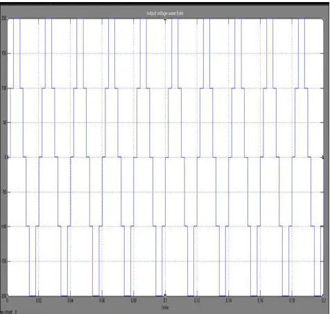
42 Fig. 5 Output voltage waveform of nine level inverter
Figure 6 shows the Matlab/Simulink Model of Three Phase Multistring based Multilevel Inverter with R-load.Figure 7, shows the three phase output voltage of three phase multi string Nine level inverter.
Fig. 6 Matlab/Simulink Model of Three Phase nine level Inverter
Fig. 7 Three phase voltage of nine level inverter
Figure 8 shows THD Analysis of Multistring Based Nine Level Output Voltage, without filter configuration we get THD is 13.84%.
Figure 9 shows THD Analysis of Multistring Based Nine Level Output Voltage, with filter configuration we get THD is 2.58%.
43 Fig. 9 THD Analysis of Nine Level Output Voltage
with filter
Fig. 10 Matlab/Simulink Model of three phase multi string nine level inverter with Induction motor drive
Figure 10 shows the Simulation circuit for three phase multi string nine level inverter with Induction motor drive, to check the outcome performance of the drive. Figure 11, 12, 13 shows the high performance induction motor drive characteristics Stator Current, Speed, Torque respectively.
Fig. 11 Waveform of stator current output
Fig. 12 Waveform of speed output
Fig. 13 Waveform of Torque Output
4. CONCLUSION
44
REFERENCES
[1] G. Ceglia, V. Guzman, C. Sanchez, F. Ibanez, J. Walter, and M. I. Gimenez, “A new simplified multilevel inverter topology for DC-AC conversion,” IEEE Trans. Power Electronics, vol. 21, no. 5, pp. 1311- 1319, Sep. 2006
[2] N. A. Rahim and J. Selvaraj, “Multistring five-level inverter with novel PWM control scheme for PV application,” IEEE Trans. Power Electronics, vol. 57, no. 6, pp. 2111-2123, Jun. 2010
[3] C. T. Pan, W. C. Tu, and C. H. Chen, “A novel GZV-based multilevel single phase inverter,” Taiwan Power Electronics conference, pp. 1391-1396, Sep. 2010.
[4] W. Yu, J. S. Lai, H. Qian, C. Hutchens, J. Zhang, G. Lisi, A. Djabbari, G. Smith, and T. Hegarty, “High-efficiency inverter with H6-type configuration for photovoltaic non-isolated AC module applications,” IEEE Applied Power Electronics Conference and Exposition, pp. 1056- 1061, 2010.
[5] F. Blaabjerg, Z. Chen, and S. B. Kjaer, “Power electronics as efficient interface in dispersed power generation systems,” IEEE Trans. Power Electronics, vol. 19, no. 5, pp. 1184-1194, Sep. 2004
[6] D. G. Infield, P. Onions, A. D. Simmons, and G. A. Smith, “Power quality from multiple grid-connected single-phase inverters,” IEEE Trans. Power Delivery, vol. 19, no. 4, pp. 1983-1989, Oct. 2004.
[7] S. B. Kjaer, J. K. Pedersen, and F. Blaabjerg “A review of single-phase grid-connected inverters for photovoltaic modules,” IEEE Trans. Industry Applications, vol. 41, no. 5, pp. 1292-1306, Sep./Oct. 2005.