High Energy Line Breaks. Design Requirements and Engineering Practice.
Alexey Berkovsky1), Alexander Kultsep1), Leonid Lyakishev2)1) CKTI – Vibroseism, Saint Petersburg, Russia 2) FSUE OKB "GIDROPRESS", Podolsk, Russia ABSTRACT
Requirements for protection of Nuclear Power Plants against postulated ruptures of High-Energy Piping systems in terms of defence-in-depth concept present practically in all National and International Guides for NPP Design.
During the last decades this problem was somehow shadowed by the successful implementation of LBB approach that proves not occurrence of piping break before a detectable leak will appear. However, implementation of LBB has a some evident limitations such as: sensitivity of detection devices for small piping diameters, uncertainty in loading conditions, fracture mechanisms of crack growth's that do not comply with LBB hypothesis, accessibility of monitored piping segments and finally, high cost of required hardware.
From engineering point of view High Energy Line Breaks (HELB) problem involves multidisciplinary consideration that require an essential knowledge in the different fields, such as: structural mechanic and dynamic, hydrodynamic, plant technological arrangement and so on.
Three main steps of HELB consideration: postulation of pipe break locations, assessment of break consequences and providing of safety measures are illustrated with practical implementation for safety significant WWER -1000 High Energy Line.
Special emphasis in paper is given to the analytical investigation of the pipe whip motion with discussion of different aspects for numerical modelling and result's interpretation. An example of such calculation is presented and it’s shown that a reliable whip motion prediction is possibly if both: the surrounding structures like other pipelines or building parts and material failure limits of the High-Energy Piping are taken into account.
DESIGN REQUIREMENTS
The principle of defence-in-depth established in the safety design basis of nuclear power plants requires consideration of all design as well as beyond design situations from the point of view plant and public safety. Rupture of High Energy Lines could be treated as one of such possible events.
Definition of High Energy Lines in engineering practice postulates that "any system or portion of system where the maximum operating pressure or the maximum operating temperature exceed certain threshold (e.g. 20 bar and 100°C), during normal plant operating conditions. Above these limits for only a relatively short portion (less than approximately two percent) of the period of time to perform their intended function, may be classified as moderate energy" [1]. The following consequences of high-energy pipe ruptures should be considered in the plant design:
-pipe whip effects (uncontrolled motion of a ruptured pipe due to pipe break);
-jet impingement effects (jet of fluid emanating from the break point that could affect safety-related systems); -compartment pressurization (rise of pressure in compartment due to exit of steam or flashing water from the
rupture point; both: static and dynamic aspects of pressurization should be evaluated); -flooding effects (water falling to the floor and draining to adjacent regions);
-missiles generation (sudden rupture of the pipe could produce missiles capable reach a safety-related targets);
-environmental effects (change of temperature, pressure, humidity and radiation environment).
All or one of these consequences could form a Postulated Initiating Event (PIE) in terms of IAEA Safety Guide No. NS-G-1.11 [2] that in its turn requires a detailed consideration for Plant Safety from point of view one or more of the three safety functions such as: (a) the control of reactivity; (b) the removal of heat from the core; and (c) the confinement of radioactive material and the control of operational discharges, as well as the limitation of accidental releases.
Several comprehensive documents give a detailed description of all steps needed for analysis of High-Energy Lines phenomena. The most detailed evaluation is presented in American Standard ANSI/ANS-58.2 "Design Basis for protection of light water nuclear power plants against the effect of postulated pipe ruptures" [3]. The basic principles and recommendations described in this document are:
-piping ruptures are classified as piping breaks (circumferential and longitudinal), throw-wall cracks and leakage cracks, location and geometry of each rupture is considered;
-each piping rupture postulates one at a time; -ruptures are postulated in the system's terminal ends;
-intermediate ruptures are postulated on the basis of piping fatigue and stress analysis;
-step-by-step procedure for Pipe Rupture Evaluation is presented in this Standard with necessary information for acceptable methods and models for establishing of Jet Geometry and Fluid Force quantitative values; -Standard permits use of Leak-Before-Break Approach to justify postulating a leakage crack instead of pipe
environmental and flooding effects should be evaluated in this case. Location of pipe ruptures
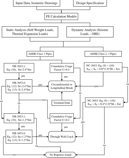
Fig. 1 shows a principal flow-chart for procedure that could be implemented for location of postulated piping ruptures according to ANSI/ANS – 58.2 Standard [3]. To perform such evaluation the following stages of analyses should be done for High-Energy piping systems:
-static analysis (deadweight and thermal expansion); -dynamic (seismic) analysis.
Static analysis is carried out under gravity loads due to dead and live weights (i.e. pipe material, insulation, fluid medium) and design pressure. Thermal expansion analyses of piping systems are performed for all designated sets of piping operational conditions for evaluation of corresponded ASME BPVC equations and performing of fatigue analysis.
In frame of dynamic analysis piping internal forces and moments should be calculated under seismic input corresponding to OBE level.
The following set of ASME Class 1 equations are considered according to ANSI/ANS – 58.2 Standard [3] and ASME BPVC NB-3600:
-Satisfaction of Primary Plus Secondary Stress Intensity Range under the combination of loadings for which either Level A or Level B service limits have been specified (Equation N 10, NB-3653.1):
≤ − × + + = m m b b a a ab i n S S T T E C M I D C t D P C S 2 . 1 4 . 2 2 2 3 0 2 0 0
1
α
α
(1)Nomenclature for this and following equations corresponds to the terminology from ASME BPVC [9].
According to presented flow chart, if condition: Sn < 1.2*Sm is satisfied, then no piping rupture is postulated in the given location.
In opposite case, an additional investigation is performed: Check of Equation 12 (ASME NB-3653.6):
≤ = m m i e S S M I D C S 2 . 1 4 . 2 2 * 0 2 (2)
and Equation 13:
≤ − × + + = m m b b a a ab i S S T T E C M I D C t D P C S 2 . 1 4 . 2 2 2 ' 3 0 2 0 0
1
α
α
(3)If stress values calculated according Equations (2) and (3) are higher than 2.4*Sm, then piping break is postulated in the considered location. If stress values calculated according Equations (2) and (3) are less than 2.4*Sm, but higher than 1.1*Sm, then through-wall crack is postulated in the considered location. In opposite case no piping ruptures are postulated.
An additional condition that should be checked in the frame of performed analysis is the value of cumulative usage factor U (NB-3653.5).
To define this value the following stresses should be calculated (Equation (11), NB-3653.2):
0 0 0
1 1 2 2 3 1 3 3 2
3
1 1
2 2 2(1 ) 1
p i ab a a b b
P D D
S K C K C M K E T K C E T T E T
t I
ν
α
α
α
ν
α
= + + ∆ + − + ∆
− − (4)
and Equation (14), NB-3653.2:
2 p alt
S
S = (5) According to ANSI/ANS – 58.2: a piping break is postulated if U > 0.4, a through-wall crack is postulated if 0.2 < U < 0.4, and no piping ruptures are postulated in the given location if U < 0.2. It should be noted, that in this part ANSI/ANS approach still differs from the US NRC position [4], that use more severe acceptance criteria for fatigue: no piping breaks are postulated if the cumulative usage factor U < 0.1.
For piping system classified as Class 2, the following set of equations should be accessed:
Equation (9), NC-3653.1: ( )
2 2 0 max 1 Z M M B t D P B
S A B
n OL
+ +
= (6)
Equation (10), NC-3653.2:
Z
M
i
S
C Е*
=
(7)For location of postulated pipe rupture the following equation is checked:
+ + > + ) 8 . 1 ( 4 . 0 ) 8 . 1 ( 8 . 0 a h a h E OL S S S S S
S (8)
Input Data, Isometric Drawings
Design Specification
FE Calculation Models
Static Analysis (Self-Weight Loads,
Thermal Expansion Loads)
Dynamic Analysis (Seismic
Loads – OBE)
ASME Class 1 Pipes ASME Class 2, 3 Pipes
NB-3653.1: Eq. (10), Sn>2.4*Sm
Cumulative Usage Factor U>0.4
NB-3653.6: Eq. (12): Se>2.4*Sm
Eq. (13): S>2.4*Sm
Circumferential or Longitudinal Break
Terminal Ends
NC-3653: Eq. (9) + (10): SOL + SE > 0.8*(1.8*Sh + Sa)
NB-3653.1: Eq. (10), Sn>1.2*Sm
Cumulative Usage Factor U>0.2
NB-3653.6: Eq. (12): Se>1.2*Sm
Eq. (13): S>1.2*Sm
Through Wall Crack
NC-3653: Eq. (9) + (10): SOL + SE > 0.4*(1.8*Sh + Sa)
No Ruptures found yes
no no
yes
yes
yes
no
yes
yes
no
no no
yes no
yes
no
Fig. 1 Logic Diagram for Postulation of ruptures in High Energy Lines.
PRACTICAL IMPLEMENTATION.
Three main steps of HELB consideration: postulation of pipe rupture locations, assessment of break consequences and providing of safety measures are illustrated with practical implementation for safety significant WWER -1000 High Energy Line.
Description of system.
Quick boron injection system (QBIS) is a special system for management of beyond-design basis accidents without scram and is intended to bring the reactor core to subcriticality by injection of the concentrated solution of boric acid into the primary circuit in case of failure of the reactor control and protection system.
QBIS consists of four independent channels, each of them includes a tank with boric acid solution, connecting pipelines that link the tank and the main coolant pipeline, small-bore pipelines DN 25 and valves. Boric acid solution in the tank is heated by the electric heaters unit.
QBIS channel is installed on the Reactor Cooling Pump (RCP) set bypass line and supplies the concentrated solution of boric acid into the primary circuit at the expense of pressure differential on the RCP set suction-head and during its rundown.
Connecting pipelines DN 200 are made of the corrosion resistant steel 08Х18Н10Т and equipped with two quick-acting shut-off valves (normally closed) and two isolation gate valves (normally opened). Two sliding weight supports are installed under each shut-off valve. For seismic restraining connecting pipes are equipped with two pairs of hydraulic snubbers located on the vertical piping runs. Design specification provides all operation modes that QBIS could experience during its lifetime. It includes different normal operating and accidental regimes, such as transients from the Cold to Hot (Nominal) state, Hydraulic tests, accidental QBIS operation during full power with transient to Cold State and so on. All this data forms a necessary background for the subsequent fatigue analysis.
Analysis for location of piping ruptures.
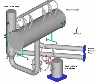
In the original design QBIS system was qualified according to the Russian Strength Code PNAE [5]. However, for HELB analysis, an ASME BPVC NB-3600 calculations were performed to locate an intermediate piping ruptures. For Stress and Fatigue Analyses a comprehensive beam FE model of QBIS piping and adjacent Primary Circuit has been developed (Fig. 2). All piping stress and fatigue analyses have been done with use of dPIPE software [6].
Fig. 2 FE Calculation model for location of intermediate ruptures.
Results of performed analyses have shown that according to the criteria set in Standard ANSI/ANS-58.2-1988 and taking into account more restrictive "0.1" fatigue NRC Criteria the following four locations have to be postulated for QBIS piping breaks for each channel (Fig. 3):
-connections of DN 200 pipelines with QBIS Tank (2 points as Terminal Ends); -connections of DN 200 pipelines with Cold Leg of MCP (2 points as Terminal Ends); -no other intermediate break's locations was found.
Moreover, analysis of postulated break locations allows to reduce a total number of ruptures for subsequent pipe-whip analysis due to consideration of QBIS design: taking into account, that 2 valves of QBIS are normally closed, in case of sudden break only a small volume of medium could exit from corresponding rupture points, so it's possible to keep only 2 locations for the futher analysis.
Pipe Whip Motion Analysis.
Evaluation of all possible consequences of postulated pipe ruptures (i.e. pressurization, jet impingement, flooding, etc) brought to the conclusion that the main concern for the considered piping systems is a pipe whip phenomenon. For this purpose a detailed FE models were developed for two QBIS pipes. The first model has a break location at the tank nozzle (Fig. 4). The whip motion of this pipe is limited by the restraining frame specifically designed to take piping whip reaction. Hence, the objective of this analysis was to qualify this frame capacity to stop piping whip motion. The second model has a break location on the main coolant circulation pipe nozzle. The motion of this pipe is restricted by surrounding structures (Fig. 5). The aim of this analysis was to investigate the interaction of ruptured pipe with the neighboring safety-related piping.
QBIS Piping on side of RCP set suction-head Piping on side of RCP intake
Fig. 3 Results of Analysis for location of pipe ruptures.
frame valves
pipe break location (Tank Nozzle)
support snubbers Main Coolant
Fig. 5 Pipe Whip Analysis Model 2.
Obviously the FE calculations have to be performed as non-linear dynamic with large motions and large plastic deformations including contact non-linearity. Therefore an appropriate choice of element size and element formulation is especially important. A numerical and experimental investigation on plastically deformed pipes [7] can be referring as an example of such choice. In this paper it is recommended to use LS-DYNA full integrated (4 points) shell elements with 5 thickness layers. The used element size counted 1.25 times of pipe wall thickness. An investigation regarding used element size and formulation has been performed on the presented Model 1. For that purpose two test models were prepared. The model A had 32 elements along pipe circumference with ratio element size to element thickness in the range of 0.95 to 1.5 for different pipe locations. The model B had twice reduced element size compared to the model A. The calculated impact force between striking pipe and affected member (frame) is presented in Fig. 6. For the model A two cases of element formulation have been investigated: for one calculation Belytschko-Lin-Tsay shell elements with reduced integration were used (curve ‘model A’ in Fig. 7). For another calculation Huges-Liu shell elements with 4 integration points on element side were used (curve ‘model A full integration’ in Fig. 6). For the calculation with refined mesh the Belytschko-Lin-Tsay shell elements were used (curve ‘model 2 (fine mesh)’ in Fig. 6). The difference between calculated first peak forces for all cases is less than 2% that can be considered as reliable result for engineering purposes. However larger differences (about 6% for maximum force value) can be observed for the vibration peaks following the first impact.
Fig. 6 Impact force on frame: influence of element size and element formulation on the results. A set of hydrodynamic loads acting on QBIS just after occurrence of postulated pipe break was established apart
collision with other safety-related pipe
pipe break location
from pipe-whip analysis in assumption that pipe deflection and deformation have insignificant effect on the hydrodynamic loads. Then these loads were dynamically applied to QBIS model. Mathematical model of material of shell elements in regions of assumed interactions was chosen as isotropic elastic with kinematic hardening plasticity. All pipe-whip analyses were carried out with use LS-DYNA[8].
The following results of the performed analyses were established and considered: -all range of reaction loads on the pipe supports and whip-restrainer frame;
-pipe motion path and relative displacements between the pipe and surrounding structures; -dynamic behaviour of surrounding structures affected to collision with the swung pipe; -impact forces on the affected surrounding structures;
-stress and strain fields of deformed pipe.
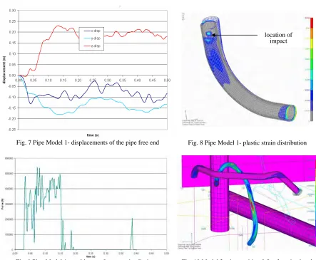
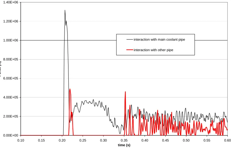
Fig. 7 – 11 show a most significant results of performed analyses. As it could be seen from these pictures pipe break in the zone of Boric Acid Tank Nozzle produces an acceptable level of pipe whip motion (~0.17 m in horizontal plane and 0.24 m in vertical direction). It was proved by strength calculations that restraining frame reliable takes up piping reaction force. In case of Model 2 with postulated break on the main coolant circulation pipe nozzle, displacement of piping free end could achieve value of 5 m, in spite of the fact, that this motion is limited by surrounding piping and structures. Analysis of piping interactions that could occur in this case led to recommendation to install a special piping whip restraining device, that should be fixed on both sides of pipe in assumed break's place to prevent not only whip motion but jet impingement effect as well.
Fig. 7 Pipe Model 1- displacements of the pipe free end Fig. 8 Pipe Model 1- plastic strain distribution
Fig. 9 Pipe Model 1- total impact force on pipe limiter Fig. 10 Model 2: pipe position 0.5s after pipe break location of
0.00E+00 2.00E+05 4.00E+05 6.00E+05 8.00E+05 1.00E+06 1.20E+06 1.40E+06
0.10 0.15 0.20 0.25 0.30 0.35 0.40 0.45 0.50 0.55 0.60
time (s)
F
o
rc
e
(
N
)
interaction with main coolant pipe
interaction with other pipe
Fig. 11 Model 2: total impact forces on surrounding structures SUMMARY AND CONCLUSIONS
A short review made here for High Energy Line Break problem is to underline a significance of HELB hazard in the light of Nuclear Power renascence era observed in the recent few years. A number of Units in East and even in West Countries are now on the design stage. From this point of view the question of special importance is harmonizing of Codes and Standards developed more than 20 – 30 years ago to the modern requirements and analytical capabilities. One of such activities is under way now in Russia – development of national guide for protection of NPP against ruptures of High Energy Lines that should be consistent with International Practice and National Codes as well [10]. Presented numerical results demonstrates a possibility of comprehensive analysis to answer question not only for Code Compliance but also for issuing an important recommendations significant for Plant Safety.
REFERENCES
1. European Safety Practice on the Application of Leak Before Break (LBB) Concept, European Commission, Report EUR 18549 EN
2. IAEA Safety Guide No. NS-G-1.11, "Protection against Internal Hazards other than Fires and Explosions in the Design of Nuclear Power Plants", IAEA, 2004
3. ANSI/ANS-58.2-1988. “Design Basis for Potential of Light Water NPP Against the Effects of Postulated Pipe Rupture”
4. Standard Review Plan, NUREG 0800, part 3.6.2, Determination of rupture locations and dynamic effects associated with the postulated rupture of piping, Rev. 1, July 1981
5. Norms for strength calculations of equipment and pipelines of nuclear power facilities. PNAE G-7-002-86. 6. Computer Software Code For Piping Dynamic Analysis dPIPE, Verification Manual Report No. co06-96x.vvk,
St. Petersburg, 1997
7. Harrison David K., De Silva Anjali K.M., FEA-Simulation of bending process with LS-DYNA, 8th International LS-DYNA User Conference
8. LS-DYNA Users manual. April 2003, Version 970. Livermore Software Technology Corporation.
9. ASME Boiler and Pressure Vessel Code, Section III, Subsections NC, ND, NF. Edition 1992. ASME, New York, 1992.
10. Berkovsky A., Kostarev V., Stevenson J. "Adaptation of the Modern Approaches for Protection of Nuclear Power Plants against the Effects of Postulated Pipe Ruptures to the Russian National Guides. Problems and Experience", Transactions of the 17th International Conference on Structural Mechanics in Reactor Technology, paper F278, August 2003.