Research Development Cell, Government College of Engineering, Jalagon (M. S), India
Optimal PMU Placement Using Binary
Integer Programming
Puja V. Deshmukh1, P.P. Bedekar2
M.Tech Student, Department of Electrical Engineering, Government college of Engineering, Amaravati, India1
Associate Professor, Department of Electrical Engineering, Government college of Engineering, Amaravati, India2
ABSTRACT: Optimalphasor measurement units (PMUs) placement involves the process of minimizing the number of PMUs needed while ensuring the entire power system completely observable. A power system is identified observable when the voltages of all buses in the power system are known. Cases with and without the zero injection measurements are considered. The optimal PMU placement problem can be achieved using linear constraints. This implies that optimal PMU placement problem with zero injection busses can be solved by standard Binary Integer Programming (BIP) solvers. Subsequently, a simple and an effective methodology has been presented to handle single PMU outage as well as single line outage in the system.
KEYWORDS: Binary integer linear programming, optimal PMU placement, maximum redundancy, failure of PMU / Communication line.
I. INTRODUCTION
For secure operation of power system requires close monitoring of the system operating condition. The collection of all the positive sequence voltage phasor in the power network is defined as state. The state estimator uses conventional measurements (such as complex powers, voltage magnitudes and current magnitudes) from substations to calculate the state with an iterative nonlinear procedure. At present, the precision and the observability of the state estimator are limited by the innate efficiencies of conventional measurements. These measurements are commonly provided by the remote terminal units (RTU) at the substations and include real/reactive power flows, power injections, and magnitudes of bus voltages and branch currents [1]. Until recently, it was not possible to measure the phase angle of the bus voltage in the real time due to the technical difficulties. The advent to Phasor Measurement unit (PMU) is an important tool for monitoring and control of power system. The PMU is able to measure the voltage phasor of the installed bus and the current phasors of all the lines connecting to the bus, i.e., a PMU can make installed bus and its neighboring buses observable.
The phasor measurement unit embeds the global positioning system (GPS) receiver clocks to achieve the synchronizing of sampled signals at nominated locations of the entire power network. In the real-life system, the PMU receives the voltage and current waveforms as inputs, which are derived from standard Current Transformer (CT) and Potential Transformer (PT). the input signals are isolated, filtered and sampled at an effective rate of 48 sampled per cycle of the fundamental frequency [2]. But overall cost of this metering device is high and also lack of communication facilities in substation. For that minimizing number of PMU’s and also finding optimal location is the main objective and making complete system observable. Accordingly, Optimal PMU Placement (OPP) problem of finding the least number of required PMU’s and their installation location in the presence of fixed conventional measurements.
Research Development Cell, Government College of Engineering, Jalagon (M. S), India
In recent years, there has been significant research activity on the problem of finding the minimum number of PMUs and their optimal locations. In [1], a simulated annealing method is used to find the optimal PMU locations. There is, however, a possibility that aplacement set that can make the system observable beoverlooked by this search process.In [3], a bisectingsearch method is implemented to find the minimumnumber of PMUs to make the system observable. Thesimulated annealing method is used to randomly choosethe placement sets to test for observability at each step of the bisecting search. In [4-6], a genetic algorithm is used to find the optimal PMU locations. The minimum numberof PMUs needed to make the system observable is found by using a bus-ranking methodology. A methodology for PMU placement for voltage stability analysis in power system is developed in [7]. Reference [8] introduced a strategic PMU placement algorithm to improve the bad data processing capability of state estimation by taking advantage of PMU technology. In [9] and [10], the authors propose an exhaustive search-based methodology to determine the minimum number and optimal locations of PMUs for complete observability of the power system.
Xu and Abur [11] adopted integer linear programming (ILP) approach which allows easy analysis of network observability for mixed measurement sets based on conventional measurements. It was further enhanced through topology modification by merging the bus that has injection measurement with one of its neighbors [12]. Gou [13] introduced a simpler algorithm that was then revised for the cases of redundant PMU placement, full observability and incomplete observability [14].Branch and bound (B&B) method was proposed by Mohammadi-Ivatloo and Hosseini.To solve an OPP problem considering secondary voltage control. Mixed integer linear programming (MILP) was used to solve the OPP problem by considering PMU placement and maximum redundancy of the system simultaneously with the maintenance of system reliability [15].
Zero injections busses, which are analogous to transshipment nodes, have the potential to reduce the number of PMUs required for complete system observability. Ref. [16] considers modeling of zero injection constraints in an otherwise ILP framework. In the resulting formulation, observability constraints arising out of zero injection busses turn out to be non-linear. This increases the complexity of the discrete optimization problem. The significant aim of this paper is to find the optimal number and locations of the PMU’s to make the system topologically observable. For solving the binary integer programming model, we use the bintprog solver in MATLAB, which minimized a linear objective function subject to linear inequality constraints. The OPP problem is formulated as a BIP problem. The BIP uses a linear programming based bound & branch algorithm. For that algorithm, only branch-bus model is the network is needed for reduced number of PMU’s and their optimal location.
II. PROBLEM FORMULATION
A PMU is able to measure the voltage phasor of the installed bus and the current phasors of some or all the lines connected to that bus. The following rules can be used for PMU placement.
Rule 1: Assign one voltage measurement to a bus where a PMU is placed, including one current measurement to each branch connected to the bus itself (fig 1 a).
Rule 2: Assign one voltage pseudo-measurement to each node reached by another equipped with a PMU.
Rule 3: Assign one current pseudo-measurement to each branch connecting two buses where voltages are known (fig 1 b). This allows interconnecting observed zones.
Rule 4: Assign one current pseudo-measurement to each branch where current can be indirectly calculated by the Kirchhoff current law (KCL). (fig.1.c)
This rule applies when the current balance at a node is known [17].
Research Development Cell, Government College of Engineering, Jalagon (M. S), India
With the help of Ohm’s law, a PMU placed at a given bus is capable of measuring the voltage phasor as well as the phasor currents for all lines incident to that bus. The objective of the PMU placement problem is to make the system observable by placing minimum number of PMUs.
A. DETERMINING MINIMUM NUMBER OF PMU’S
Formulation of problem to obtain minimum number of PMUs required for complete system observability considering one line/ PMU outage is considered in this part. For an n-bus system the optimum PMU placement problem can be formulated as:
n
i i i
x
w
p
1
min
(1)Subject to the constraint Ax > v(2)
where, p is number of PMUs
x is a binary decision variable vector, whose entries are defined as: xi =1 if a PMU is installed at bus i
= 0 otherwise
Wiis the cost of PMU installed at bus i. Minimum PMU placement problem is obtained by setting all weights to unity. A is the binary connectivity matrix of the system, whose entries are defined as:
Aij = 1 if either i=j or if i and j are adjacent nodes = 0 otherwise
v is a vector of length n. Each element of vector v, is set to 2. This ensures that each bus is observed by at least two PMUs. Because of this, each bus will remain observable even in case of outage of one PMU or outage of one line. If line outage/ PMU outage is not to be considered, then each element of vector vis set to 1.
B. FINDINGOPTIMUMLOCATIONOFPMU’S
After determining the minimum number of PMUs required, their optimum location is obtained, such that maximum redundancy in the buses observed is achieved. This problem can be formulated as-
n
Ax
sum
MaxR
(
)
(3) subject to the constraints:Ax > v
p
x
n
i i
1
(4)
where, p, x, A, n, and v have the same meaning as that in part A of the problem, sum (A x) represents the sum of elements of vector (A x), and R is the redundancy in the buses observed.
III.BINARY INTEGER PROGRAMMING
x
f
T*
min
(5)Such that,
A
eq*
x
b
eq(6)where,x is binary
For a n - bus system, the OPP problem can be formulated as follows.
n
i i i
x
w
p
1
Research Development Cell, Government College of Engineering, Jalagon (M. S), India
Subject to constraint,
1
)
(
x
Ax
f
(8)where x is the vector of binary decision variables, whose ithentry xi is equal to 1, if a PMU is installed at bus i and 0 otherwise, wi is the cost of a PMU installed at bus i, and f (x) is a vector function, whose entries are non-zero if the corresponding bus voltage is solvable using the given PMU placement set and 0 otherwise. Usually we set wi =1, i, meaning that all PMUs have the same priority of placement [18]
The entries of the binary connectivity matrix A are defined as follows:
otherwise
if
ted
mareconnec
k
if
m
k
if
A
km0
&
1
1
. (9)
where,
1
is a vector whose entries are all equal to one.
A. BINARY INTEGER PROGRAMMING:
For solving the BIP model (7) - (9), we use the bintprog solver of MATLAB [6], which minimizes a linear objective function subject to linear inequality constraints. Each variable in the optimal solution must be either 0 or 1. The steps for the implementation of the BIP model are:
Step 1: Read the network branch/bus data.
Step 2: Form the binary connectivity matrix and the PMU cost coefficient vector. Step 3: Form the right- hand side unity vector.
Step 4: Solve the BIP problem.
The PMU cost vector, the binary connectivity matrix and the unity vector are the inputs for the bintprog. The output of the program is the number and the optimal locations of PMUs [18].
B. OPTIMAL PMU PLACEMENT FORMULATION:
The objective of the OPP problem is to minimize the number of PMUs allowing the power system to be completely observed. It is assumed that the PMU has enough channels to measure the voltage phasor of the installation bus and the current phasors of all the lines emanating from that bus [19]. Consequently, the voltage phasors of all adjacent buses will be solvable using the monitored phasor currents along the lines incident to that bus and the known line parameters. In this section, an ILP formulation [19] is used to obtain the optimal solution.
C. SINGLE LINE/PMU OUTAGE
In day to day world, fault occurrence in power system is very common. Hence the PMU can become faulty in a bus system. To overcome this problem, we should consider the PMU outage case. The observability for each bus in this case would increase from one to two. This practically means that in case of losing any single PMU or single line from the system, the whole power network will remain observable. However, as PMUs are highly reliable devices, the occurrence probability of both contingencies at the same time is practically near zero and then has not been considered in this method. This will enhance the system reliability [20].
IV. ZERO INJECTION BUSES
Research Development Cell, Government College of Engineering, Jalagon (M. S), India
The zero injection at a system bus provides an equation that allows the calculation of the complex bus voltage of that zero injection bus or any one of its associating buses, provided that all remaining associating buses are observable.
n
i i
x
Min
1
(10)
Tzero* P*A*X ≥ b2 (11)
Subject to, X = [x1,x2,x3…..xn] (12)
b2 = [b21, b22]
b21 = [1,1,1…….]nnas*1
b22 = [ncbi; i= 1,2….nzi]
Tzero =
meas M
M
T
I
0
0
*(13)
where, P = permutation matrix
A= bus-to-bus incidence matrix
ncbi = number of buses associating ZIB
M = nnas= number of buses not associating with ZIB
Tmeas = zero injection bus-to-bus incidence matrix
Tzero = ZIB associating buses
ZIBs have the potential to minimize the number of PMU required for complete observability of the system.in figure. 2, the buses 1,2 and 4 are connected with the bus-3 the current I13, I23 and I43 respectively, whereas the ZIB bus-5 is connected with the bus-3 with no current [21].
1 5
I
2 I
3
4 I
Research Development Cell, Government College of Engineering, Jalagon (M. S), India
V.CASE STUDY
Case 1:Without considering zero injection bus:
In this case, zero injection buses are ignored from the test system. In order to form the constraint, set, the binary connectivity matrix A, will be formed first. Matrix A can be directly obtained from the bus admittance matrix by transforming its entries into binary form.
6
5
1 2 3
4
7
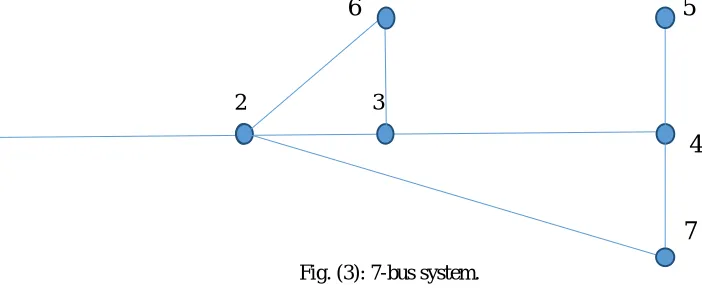
Fig. (3): 7-bus system.
Consider the 7-bus system and its measurement configuration shown above. Building the A matrix for the 7-bus system of Fig (3) yields:
1 0 0 1 0 1 0
0 1 0 0 1 1 0
0 0 1 1 0 0 0
1 0 1 1 1 0 0
0 1 0 1 1 1 0
1 1 0 0 1 1 1
0 0 0 0 0 1 1
A
(14)
The operator “+” serves as the logical “OR” and the use of 1 in the right hand side of the inequality ensures that at least one of the variables appearing in the sum will be non-zero. The constraint f1≥ 1 implies that at least one PMU must be placed at either one of buses 1 or 2 (or both) in order to make bus 1 observable. Similarly, the second constraint f2 ≥ 1 indicates that at least one PMU should be installed at any one of the buses 1, 2, 3, 6, or 7 in order to make bus 2 observable [22].
Research Development Cell, Government College of Engineering, Jalagon (M. S), India
1
1
1
1
1
1
1
)
(
7 4 2 7 6 3 2 6 5 4 5 7 5 4 3 4 6 4 3 2 3 7 6 3 2 1 2 2 1 1x
x
x
f
x
x
x
f
x
x
f
x
x
x
x
f
x
x
x
x
f
x
x
x
x
x
f
x
x
f
x
f
(15)Case 2:With considering zero injection bus:
This case considers the most general situation where zero injection buses are presentedin the power system. Consider again the 7-bus system shown in Fig.1, where bus 3 is assumed to be a zero injection bus. In this case, it is easy to see that if the phasor voltages at any three out of the four buses 2, 3, 4 and 6 are known, then the fourth one can be calculated using the Kirchhoff’s Current Law applied at bus 3 where the net injected current is known. Hence, the constraints associated with these buses will have to be modified accordingly as shown below:
1
*
*
4 63 7 6 3 2 1
2
x
x
x
x
x
f
f
f
f
1
*
*
3 62 7 5 4 3
4
x
x
x
x
f
f
f
f
(16)1
*
*
3 42 6 3 2
6
x
x
x
f
f
f
f
The operator ‘.’ serves as the logical “AND” in the above equations. The expressions for fi can be further simplified by using the following properties of the logical AND (.) and OR (+) operators. Given two sets A and B, where set A is a subset of set B, Then A+B=B and A·B=A [24].
Applying this simplification logic to all expressions will yield:
7 6 3 2 1
2
x
x
x
x
x
f
≥ 17 5 4 3
4
x
x
x
x
f
≥ 1(17)6 3 2
6
x
x
x
f
≥ 1Note that the constraints corresponding to all other buses will remain the same as given in equation (14). One exception is the constraint for bus 3 where the injection is measured (or known). This constraint will be eliminated from the constraint set. The reason for removing the constraints associated with injection buses is that their effects are indirectly taken into account by the product terms augmented to the constraints associated with the neighboring buses [23].
V. RESULTS
Research Development Cell, Government College of Engineering, Jalagon (M. S), India
When the concept is extended to all buses, the network global observability will be directly maintained, with possible single ormultiple PMU / Communicationline loss. It should be admitted that when the problem is solved in this way, a higher number of PMUs will be expected for the network observability. The method can also be made adaptive. Different numbers can be assigned to the right hand side vector to account for different levels of PMU loss. These numbers can be assigned according to the heaviness of connectivity of each bus in the system[23]. For IEEE 14 bus system, considering all the constraints, the optimum no. of PMU required for meeting objective function is found to be 9 with different level and different combination of number, only the placement of PMU changes. The cost of all PMUs are assumed to be equal at 1 p.u.
Costs of PMU differ and increases as the number of channels. Unequal cost of the PMUs in the formulation of the problem is not considered in this paper as the maximum no. of measure and at any bus is not more than 7 for any mentioned cases for IEEE 14 bus system. Thus PMU is assumed to have sufficient no. of channels. The PMU placement at zero-injection buses will help find the optimal solution. PMUs at zero injection buses measure current phasors of corresponding lines; thus, the KCL at zero-injection bus provides no additional information. The removal of PMUs from zero-injection buses will reduce the search space which could enhance the solution speed. Thus with zero injection bus in system reduces no. of PMU[23].
A.EFFECTOFSINGLELINEOUTAGE
k
i j l
Fig. (4) Mutual bus
Line outage is one of the contingencies which can be detrimental to system observability. In general, loss of a branch in a power system leads to lose an observability path and sometimes an auxiliary observing source. As another example, by losing a branch connected to a ZIB, the other terminal bus has not the opportunity to use the ZIB property.
So, it is sufficient to perform the following steps to consider the impact of single branch outage on the placement problem shown in fig. (4).
Step 1:Remove the kth branch from the system and consequently, two arrays of initiate A matrix change from 1 to 0. The obtained matrix is named Ak.
Step 2: By using AK, form AKnewaccording to the algorithmexplained
Step 3:The observability constraints for the kth branch outage are set as follows: AKnew *X ≥ I (18)
Step 4: Repeat 3 above steps for outage of all branches and make a set of constraints as (18) for each one.
B.EFFECTOFSINGLEPMUOUTAGE
PMU, as a device, may be inactive due to failure of microprocessor,communicational system, etc. In such case, to keepthe entire power system observable after a PMU outage, morePMUs should be installed. The proposed method considersa PMU outage contingency by the implementation of thefollowing steps.
Step 1: Form the Anewmatrix as mentioned before.
Step 2: Each row of the Anewmatrix with n nonzero arrays is decomposed to n separate rows that each of them is generated by changing only one of the nonzero arrays of the initial row to zero.
Step 3: obtained after step 2, which is called Apnew.
Step 4: The set of constraints that makes the system observable after a PMU outage, is written as follows: APnew *X ≥ I (19)
Research Development Cell, Government College of Engineering, Jalagon (M. S), India
Table 1: System information of All the IEEE test bus systems.
Test System No. of zero injection buses Location of zero injection buses
IEEE 14-bus system 1 7
IEEE 24-bus system 4 11, 12, 17, 24
IEEE 30-bus system 6 6, 9, 22, 25, 27, 28
Case 2: The results of proposed method without and with zero injection measurement are displayed in Tables 2 and 3 respectively. In case of zero injection buses, higher values of measurement redundancy maximize the observability ofpower system buses. Table 2 shows the results of proposed method without considering zero injection buses. In case 1 single result is obtained so there is no need for redundancy measurement to obtained the best result in Table 2.
Table 2 : Results for all the test systems without considering zero injections
Test System Optimal No. of PMUs Optimal location of PMUs
IEEE 14-bus system 4 2,6,7,9
IEEE 24-bus system 7 2, 3, 8, 10, 16, 21, 23
IEEE 30-bus system 10 1, 7, 9, 10, 12, 18, 24, 25, 27, 28
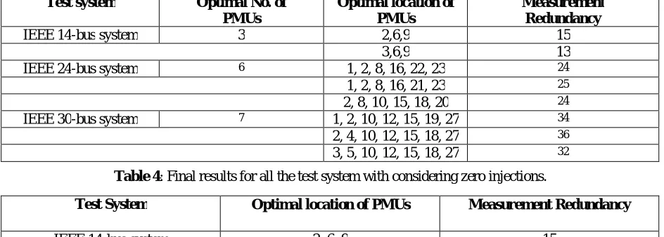
Case 3: Now Table 3 shows the test results of proposed method having more than one optimal placement of PMUs set considering zero injection buses. In case 2, IEEE 14- bus test system has three optimal number of PMUs and their location are {2, 6, 9} &{3, 6, 9}. Redundancy value of first set (2, 6, 9) is 15 and for second set (3, 6, 9) is 13.
Case 4: According to the proposed method best result has the maximum redundancy value so the final optimal PMU set is {2, 6, 9}. Table 4 shows the best solution of optimal placement of PMUs in power system considering zero injection buses on the basis of measurement redundancy value from Table 3.
Table 3: Results for all the test system with considering zero injections
Test system Optimal No. of PMUs
Optimal location of PMUs
Measurement Redundancy
IEEE 14-bus system 3 2,6,9 15
3,6,9 13
IEEE 24-bus system 6 1, 2, 8, 16, 22, 23 24
1, 2, 8, 16, 21, 23 25
2, 8, 10, 15, 18, 20 24
IEEE 30-bus system 7 1, 2, 10, 12, 15, 19, 27 34
2, 4, 10, 12, 15, 18, 27 36
3, 5, 10, 12, 15, 18, 27 32
Table 4: Final results for all the test system with considering zero injections.
Test System Optimal location of PMUs Measurement Redundancy
IEEE 14-bus system 2, 6, 9 15
IEEE 24-bus system 1, 2, 8, 16, 21, 23 25
Research Development Cell, Government College of Engineering, Jalagon (M. S), India
VI. CONCLUSION
A binary integer programming for optimal PMU placement is presented in this paper. This method is based on modification in binary connectivity matrix of the power system and incorporate the effect of zero injection buses. The effect of PMU loss and communication line outage are also consideration. The proposed method obtains optimal solution using binary connectivity matrix modification and makes the results topologically observable by placing a set of PMUs. The method is applied to IEEE system, experimental results for which shows the effectiveness of the proposed method in obtaining the obtaining the minimum number PMUs required for complete observability of power system and also its advantage of computational efficiency.
REFERENCES
[1] R.F. Nuqui and A.G. Phadke,“Phasor measurement unit placement techniques for complete and incomplete observability,” IEEE Trans. Power Del., vol.20, no. 4, pp. 2381-2388, Oct. 2005.
[2] B. Phani Ranga Raja, K.Naresh,A. Balaji, M. Rambabu, “Optimal Placement Approach of Phasor Measuring Unit by GPS,” International Electrical Engineering Journal (IEEJ) Vol. 7 (2016) No.4, pp. 2223-2227 ISSN 2078-2365. 2016.
[3] T.L. Baldwin, L. Mili, M.B. Boisen, R. Adapa, “Power System Observability with Minimal Phasor Measurement Placement”, IEEE Trans. on Power Syst., Vol. 8, No. 2, pp. 707-715, May 1993.
[4] B. Milosevic, M. Begovic, “Nondominated Sorting Genetic Algorithm for Optimal Phasor Measurement Placement”, IEEE Trans. on Power Syst., Vol. 18, No. 1, pp. 69-75, Feb. 2003.
[5] V.Ya. Lyubchenko, D.A. Pavlyuchenko, “Reactive Power and Control by Genetic Algorithm and Artificial Neural Network”, International Journal on Technical and Physical Problems of Engineering (IJTPE), Issue 1, Vol. 1, No. 1, pp. 23-26, December 2009.
[6] A.A. Allahverdiev, “Application of Fuzzy-Genetic Algorithm for Solving an Open Transportation”, International Journal on Technical and Physical Problems of Engineering (IJTPE), Issue 7, Vol. 3, No. 2, pp. 119- 123, June 2011.
[7] L. Mili, T. Baldwin, R. Adapa, “Phasor Measurement Placement for Voltage Stability Analysis of Power Systems”, 29th Conference Decision and Control, Honolulu, HI, Dec. 1990.
[8] J. Chen, A. Abur, “Placement of PMUs to Enable Bad Data Detection in State Estimation”, IEEE Trans. On Power Syst., Vol. 21, No. 4, pp. 1608-1615, Nov. 2006.
[9] S. Chakrabarti, E. Kyriakos’s, “Optimal Placement of Phasor Measurement Units for State Estimation”, 7th IASTED Int. Conf. on Power and Energy Systems, pp. 1- 6, Palma de Mallorca, Spain, Aug. 2007.
[10] S. Chakrabarti, E. Kyriakos’s, “Optimal Placement of Phasor Measurement Units for Power SystemObservability”, IEEE Trans. on Power Syst., Vol. 23, No. 3, pp. 1433-1440, Aug. 2008.
[11] Xu B, Abur A. Observability analysis and measurement placement for systems with PMUs. In: IEEE PES power systems conference and exposition, 2004. IEEE; 2004. p. 1472–5.
[12] Bei X, Yoon YJ, Abur A. Optimal placement and utilization of phasor measurements for state estimation. Final Proj Report, PSERC; 2005. p. 1– 6.
[13] Mohammadi-Ivatloo B, Hosseini SH. Optimal PMU placement for power system observability considering secondary voltage control. In: 2008 Canadian conference on electrical and computer engineering. IEEE; 2008. p. 000365–8.
[14] Aghaei J, Baharvandi A, Rabiee A, Akbari MA. Probabilistic PMU placement in electric power networks: an MILP-based multi-objective model. IEEE Trans Ind Infor 2015;11(2), 1-1.
[15] Sanchez-Ayala G, Aguerc JR, Elizondo D, Lelic M. Current trends on applications of PMUs in distribution systems. 2013 IEEE PES Innovative Smart Grid Technologies Conference (ISGT). IEEE; 2013.
[16] P. P. Bedekar, S. R. Bhide, V. S. Kale, “Optimum PMU Placement Considering One Line/ One PMU Outage and Maximum Redundancy Using Genetic Algorithm,” The 8th Electrical Engineering/ Electronics, Computer, Telecommunications and Information Technology (ECTI) Association of Thailand - Conference IEEE Trans. Power Del., pp 688-691, 17-19, May 2011.
[17] K. K. Deepika, Dr. J. V. Kumar, R. S. Ravi Sankar, J. Santosh, “Binary Integer Linear Programming Method for Optimal Placement of PMU Considering Single Line or PMU Outage,” IJAREEIE, vol.5, Issue 5, May 2016.
[18] Ahmed Hamdy Ghazy Ibrahim, Said Fouad Mekhamer, Walid A. Omran, “Power System Observability of Phasor Measurement Units: A Binary Integer Programming Approach,” International Electrical Engineering Journal (IEEJ) Vol. 6 (2015) No.11, pp. 2058-2065, ISSN 2078-2365, 2015.
[19] D. Dua, S. Dambhare, R. K. Gajbhiye, and S. A. Soman, “Optimal multistage scheduling of PMU placement: an ILP approach,” IEEE Trans. on Power Delivery, vol. 23, no. 4, pp. 1812-1820, October 2008.
[20] Sanjay Dambhare Devesh Dua Rajeev Kumar Gajbhiye S. A. Soman, “Optimal Zero Injection Considerations in PMU Placement: An ILP Approach,” 16th PSCC, Glasgow, Scotland, July 14-18, 2008.
[21] Karun Puri, Dr. Gursewak singh Brar,“ Optimal Placement Of Phasor Measurement Units for Power System Observability,” International Journal of Science and Research (IJSR) ISSN- 2319-7064, Vol.4, Issue6, June 2015.
[22]Satyendra Pratap Singh and S.P. Singh, “Optimal PMU Placement in Power System Considering the Measurement Redundancy,” Advance in Electronic and Electric Engineering. ISSN 2231-1297, Volume 4, Number 6 (2014), pp. 593-598,2014.