Modeling of Rotating Reference Frame
Control of Transformerless Single Phase
Grid Tie Inverter
Disha1, Chaithra L2 , Suryanarayana K3, Dr. Nagesh Prabhu4,
Student, Department of Electrical and Electronics, NMAM Institute of Technology, Nitte, India 1
Senior Engineer, R&D, HEXMOTO Controls Pvt Ltd, Mysuru, India2
Associate Professor, Department of Electrical and Electronics, NMAM Institute of Technology, Nitte, India 3
Professor, Department of Electrical and Electronics, NMAM Institute of Technology, Nitte, India 4
ABSTRACT: Inverter plays major role in supplying harvested power from renewable energy sources to grid. The inverter should supply power to grid with high efficiency and power quality. In this system rotating reference frame control is used to supply real power to grid which having theoretically zero steady state error. Modified Unipolar Sinusoidal Pulse Width Modulation (MUSPWM) is used to increase the efficiency of the system.
KEYWORDS: Rotating reference frame, grid tie inverter, real power.
I. INTRODUCTION
Grid synchronization is a main factor to be considered to connect the power converters to the grid. This ensures the synchronized working of grid and the power converter. The grid voltage phase-angle is required to transform the grid variables from the stationary reference frame to rotating reference frame also known d-q reference frame, so that AC currents or voltages are regulated in terms of DC variables in the regulation which simplifies design of compensator
.
Transformerless single phase grid tie inverter have several advantages such as efficiency, low cost and small size. In this system current control scheme AC components are transformed into DC component, PI controller easily removes steady state error completely and provides infinite gain at fundamental frequency [1].II. SYSTEM DESIGN
ISSN(Online) : 2319-8753 ISSN (Print) : 2347-6710
I
nternational
J
ournal of
I
nnovative
R
esearch in
S
cience,
E
ngineering and
T
echnology
(An ISO 3297: 2007 Certified Organization)
Vol. 5, Special Issue 9, May 2016
generates switching sequence for grid tie inverter. The DC bus voltage is constant. The single line diagram of grid tie inverter is shown in the Figure 1.b. This shows direction of the supply current .
III.CURRENT CONTROL
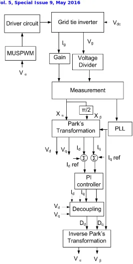
Block diagram of rotating reference current control of transformerless single phase grid tie inverter system is shown in Figure 2. Here is the current supplied to the grid, is the grid voltage and is the constant DC bus voltage. PLL tracks the angle of the grid voltage to maintain power factor of 1. In this current control scheme and are represented as . This signal is transformed to and . Where is and is leading by . and are the AC signals transformed to DC signal and using Park’s transformation as given in (1).
(1)
This are compared with the reference . Where is the current reference to supply real power and is kept zero which contributes to reactive power supply. Then the error signals generated are compensated using PI controller. Decoupling is used to decouple the voltage which is cross coupled during Park’s transformation. This decoupled signal and are transformed back to AC signal using inverse Park’s transformation. and is obtained from the Eq. (2).
(2)
The is the reference signal for MUSPWM switching generator which drives the inverter switches.
ISSN(Online) : 2319-8753 ISSN (Print) : 2347-6710
I
nternational
J
ournal of
I
nnovative
R
esearch in
S
cience,
E
ngineering and
T
echnology
(An ISO 3297: 2007 Certified Organization)
Vol. 5, Special Issue 9, May 2016
IV.SIMULATIONS RESULTS
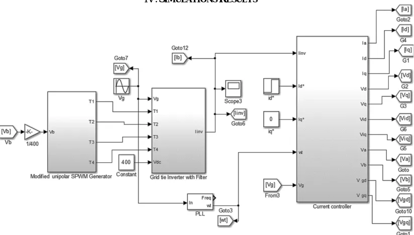
Figure 3: MATLAB Simulink model of system
MATLAB/Simulink model of grid tie inverter is shown in Figure 3. This model consists of MUSPWM, grid tie inverter with filter, and current controller blocks.
Figure 4: Current supplied to the grid and grid voltage
Figure 5: Power factor
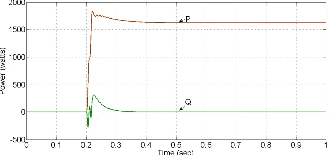
The power factor output of the system is shown in Figure 5. The real power and reactive power step response is shown in Figure 6. Here only real power is supplied to the grid in steady state.
Figure 6: Real power (P) and Reactive power (Q)
V. CONCLUSION
Transformerless Single phase grid tie inverter with rotating frame current control scheme is simulated using MATLAB/Simulink model. This system is designed to supply real power to the grid efficiently.
ACKNOWLEDGMENT
Authors gratefully acknowledge the support received from HEXMOTO Controls. Pvt. Ltd, Mysuru, R&D Centre, Nitte, NMAM Institute of Technology, Nitte Education Trust and VTU, Belagavi in carrying out the research work.
ISSN(Online) : 2319-8753 ISSN (Print) : 2347-6710
I
nternational
J
ournal of
I
nnovative
R
esearch in
S
cience,
E
ngineering and
T
echnology
(An ISO 3297: 2007 Certified Organization)
Vol. 5, Special Issue 9, May 2016
[4] Richard Zhang, Mark Cardinal, Paul Szczesny and Mark Dame, “A Grid Simulator with Control of Single-phase Power Converter sin D-Q Rotating Frame”, Power Electronics Specialists Conference, pesc 02. IEEE 33rd Annual, pp 1431 – 1436, 2002.
[5] De Souza, K.C.A., dos Santos, W.M.,Martins, D.C., “A single-phase active power filter based in a two stages grid-connected PV system”, Industrial Electronics, IECON '09. 35th Annual Conference of IEEE, pp.: 114 – 119, 2009.
[6] Mohan, N., Undeland, T., Robbins, W., “Power electronics- Converters, Applications, and Design”– John Wiley & Sons, Inc. 1995.