18th International Conference on Structural Mechanics in Reactor Technology (SMiRT 18) Beijing, China, August 7-12, 2005 SMiRT18-K14-1
METHODS OF QUALIFYING ELECTRICAL CABINETS
FOR THE LOAD CASE EARTHQUAKE
Fritz-Otto Henkel*
Woelfel Beratende Ingenieure
GmbH + Co. KG
Max-Planck-Strasse 15
97204 Hoechberg / Germany
Phone: +49(0)931/49708-310, Fax: -650
E-Mail: [email protected]
Helmut Kennerknecht
Woelfel Beratende Ingenieure
GmbH + Co. KG
Thomas Haefeli
Gutor Electronic Ltd.
Finn Jorgensen
Gutor Electronic Ltd.
ABSTRACT
With the qualification of electrical system cabinets for the load case earthquake it is differentiated between the two objectives a) stability of the cabinet and b) functionality of the built-in electrical modules during and after the earthquake. There are three methods to attain these goals: analyses, tests and proof by analogy.
A common method is the shaking of a complete cabinet on a shaking table, with the advantage that stability and functionality can be proved at the same time, but with the disadvantage that quite expensive test equipment, especially a multi-axle shaking table, is necessary and that generally a cabinet which was proved for SSE is pre-affected and thus may not be incorporated into the plant offhand, i. e. the extreme example would be that the cabinet must be built twice.
As a rule, analyses are currently carried out by means of Finite-Element-Models of the supporting structure with consideration of the electrical components at least with their masses. This analysis can prove the stability and pursue the excitation until the anchoring point of the electrical components (Henkel et al., 1987). The combination of the aforementioned two methods often constitutes the best way. The stability of the cabinet is proved by calculations, the functionality of the safety-relevant modules by tests. Once tested, modules identical in construction can be used for cabinets without further testing for earthquakes of similar or lower levels.
Proof by analogy is possible only if tests or analyses of similar cabinets were done in advance. By means of the comparison of supporting structure, mass allocation and distribution, level and shape of the earthquake excitation it can be shown that the cabinet planned is covered by cabinets already tested or analysed (Katona et al., 1995). All facets of the various methods with advantages and disadvantages are discussed and explained on the basis of numerous examples.
Keywords: earthquake, stability, functionality, qualification procedure.
1 SEISMIC QUALIFICATION PROCEDURE
The system cabinets with steel frame supporting structures and built-in electric modules have basic dimensions of about 600-1600/800/2000 mm for length/depth/height and more than 300 kg mass. They may be installed separately or connected to assemblies with up to 10 m length and 10 t total mass. For electrical components which are classified 1E (safety related) seismic qualification is requested, also ageing should be taken into account.
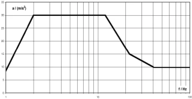
For example IEEE 344, IEC 68-3-3, USNRC Regulations, KTA 2201 or GOST 17516.1-90 may be applicable. The seismic loading will vary with the special code to be applied or by site specific definition. A response spectrum which should envelope a variety of seismic loading is defined in Figure 1. The qualification procedure is open for special specifications.
Fig. 1: Seismic loading for system cabinet: horizontal components (
∗
0.67 for vertical)
The process of “Seismic Qualification” provides three different procedures, see flow chart Figure 2: a) qualification by tests only,
b) qualification by analogy,
c) qualification by combination of calculations for the supporting frame and testing for the electronic modules Procedure a) will be established if requested by the respective code or specification or because of special effectiveness.
Procedure b) may be applicable under certain conditions and is based on a database of already qualified systems. The certain conditions are related to the following definitions:
- Identical means identical supporting construction of the system cabinet and identical or less stringent spectra
and identical modules.
- Partial identical means identical supporting construction but different mass of modules or identical supporting construction and identical module mass but different types of modules or identical module mass but different supporting construction or identical types of modules but different supporting construction or
the system is a part of an already tested one (partial difference in the supporting construction) or system cabinet identical but within limits prescribed spectra completely or partial higher than the respective from the database
- Different means prescribed spectra with big amount and throughout the whole frequency range or partial
higher than the respective from the database or completely different function of the system.
Seismic process for complete system cabinet
Seismic requirement Database of already available
qualified systems
a) certificates of systems by test b) certificates of systems by analogy c) certificates of systems by
combination of calculation and test prescribed spectrum
YES NO
identical to qualified system
partial identical to qualified system customer
requests qualification of the system
by test
certificate available in Database of already qualified systems
create new certificate of system by
test
create new certificate of system by
analogy
create new certificate of system by combination
of calculation and test
Module Qualification (see fig. 3)
no certificate required update Database of
already qualified systems
provide certificate of system to the customer / authority
End YES YES YES NO NO NO
Fig. 2: Seismic qualification procedure for electrical system cabinets
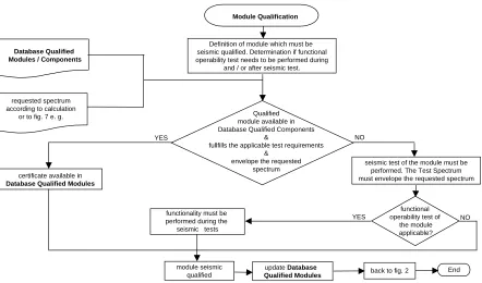
Module Qualification
Database Qualified Modules / Components
requested spectrum according to calculation
or to fig. 7 e. g.
YES
NO Qualified
module available in Database Qualified Components
&
fullfills the applicable test requirements &
envelope the requested spectrum certificate available in
Database Qualified Modules
module seismic qualified functionality must be performed during the
seismic tests
back to fig. 2 functional operability test of
the module applicable?
update Database Qualified Modules
seismic test of the module must be performed. The Test Spectrum must envelope the requested spectrum
End YES
NO Definition of module which must be
seismic qualified. Determination iffunctional operability test needs to be performed during
and / or after seismic test.
2 QUALIFICATION BY TEST
A common qualification method is the shaking of a complete cabinet on a shaking table, with the advantage that stability and functionality can be proved at the same time. However, this method is accompanied by several disadvantages:
A quite expensive test equipment, especially a multi-axle shaking table, is necessary with the capabilities of horizontal dimensions up to 10 m and masses up to 10 t e.g.
Generally a cabinet which was proved for SSE is pre-affected and thus may not be incorporated into the plant offhand, i. e. the extreme example would be that the cabinet must be built twice.
The effect on delivery time for the system is essential.
In case of malfunction of modules or of unacceptable mechanical distortions the efforts for repair or improvement measures at the system and for repetition of the tests may grow drastically.
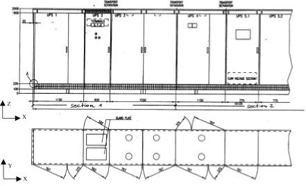
Figure 4 shows one half of a cabinet assembly which was tested in three separate sections with 3 m length and 3 t mass each. From numerous cabinet investigations yet carried out (Henkel et al., 1995) it is well known that to a large extent an earthquake analysis for the horizontal excitation direction is determined by the first global eigenfrequency and eigenmode in the respective horizontal direction. With resonance search tests for the three sections these eigenfrequencies are determined to be 6.5 Hz to 7.2 Hz for the x-direction, 5.6 Hz to 8.2 Hz for the y-direction and >24 Hz for the vertical z-direction. A connection of the three sections to the complete cabinet assembly will not involve any principal modification of the frequency situation with respect to y- and z-direction.
Y
X Z
X
Fig. 4: System cabinet assembly as part of a complete UPS system
The earthquake tests for the three sections are carried out applying artificial time histories compatible with the required response spectra (RRS) which were deduced from the floor response spectra of the erection position. The time histories of the three directions of space are applied simultaneously, five times OBE and at last once SSE. No malfunction is recognised. For completion of the qualification it must be proved that the tests with the three sections are more rigorous than tests with the complete assembly which is too large to be tested at all.
f/Hz
TRS
RRS
23 7
a/(m/s²)
Fig. 5: Response spectra (damping 5 %) required (RRS) and test (TRS), f1 = 7 Hz, f2 = 23 Hz
3 QUALIFICATION BY ANALOGY WITH RESPECT TO DATABASE
The documentation of tested systems, applied earthquake loading and test results as well as the documentation of calculated systems with results and the documentation and results of tests with single electrical modules may be gathered in a database. By means of the documents of this database including available certificates new systems may be proved by analogy, with such proof being established on the basis of comparison.
The new system is compared with those from the database with respect to identity or partial identity (see sect. 1) of the supporting frame and of type and mass distribution of the built-in modules. The prescribed seismic loading is compared with the applied one for the system cabinets or for single electrical modules available in the database. The procedure is exercised in Katona et al. (1995).
4 QUALIFICATION BY COMBINATION OF CALCULATION AND TEST
The combination of calculation and test often constitutes the best way. The stability of the cabinet is proved by calculations, the functionality of the safety-relevant modules by tests. Once tested, modules identical in construction can be used for cabinets without further testing for earthquakes of similar or lower levels.
4.1 Calculation for proof of stability and excitation of modules
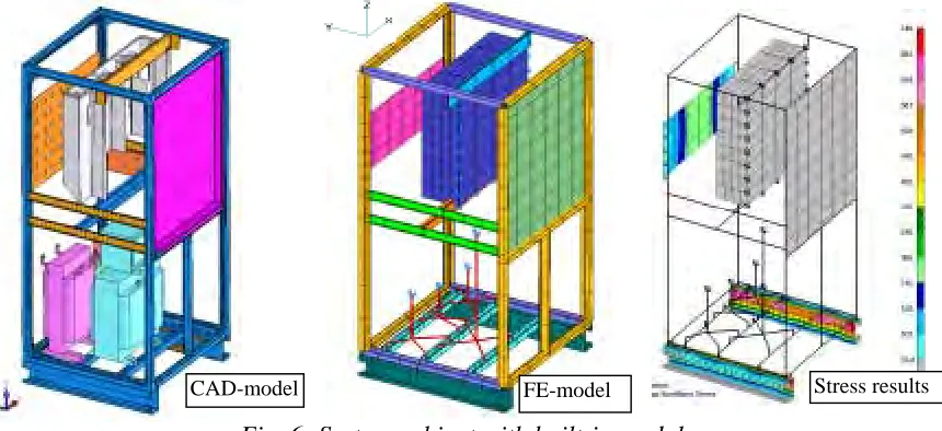
The supporting structure of a system cabinet is a steel frame with more or less stiffening elements in the frame planes of the cabinet walls. Normally, according to the technical progress the existing CAD data are transmitted to the analytical engineer for comfortable generation of a Finite-Element-calculation model. Most of the information about geometry and mass distribution may be used from the CAD data. The know-how of structural dynamics has to be added to the calculation model for input realistic boundary and transition conditions. Figure 6 shows a system cabinet without earthquake measures, the CAD-model and the deduced FE-model in comparison as well as the FE-FE-model with stress results.
Fig. 6: System cabinet with built-in modules
FE-model
CAD-model Stress results
combined with dead load. With the force and stress results allowable anchor forces and stresses are checked. In so doing the tolerable earthquake level may be evaluated for the standard construction like Figure 6. For cabinets with earthquake measures reserves for the application of higher earthquake level may be evaluated, a margin with respect to ageing may be pointed out respectively.
The same FE-model is useful to calculate test loading for seismic tests with single modules. On this behalf the FE-model is excited by artificial time histories compatible with the floor response spectra like Figure 1. With the resulting acceleration response for fastening points of modules enveloping acceleration spectra are developed. Regarding the difference between the real earthquake excitation and the excitation to be applied in the tests (e.g. sine-sweep) with single modules the enveloping spectra will be modified to the test load input.
4.2 Tests for modules
Because of the complex mechanical structure of most electrical modules proof of functionality of the safety relevant electrical modules is requested. Tests are recommended to check the electric functions during and after the dynamic impact of earthquake equivalent excitation. The test loads may be chosen in a conservative manner according to codes. The time histories of two examples are presented in Figure 7 (upper and middle graph), sine-sweep with a frequency rate of 1 octave/min and stationary frequency tests in steps of 1/3rd octave with requested acceleration amplitudes of 3 g or 3.5 g respectively.
The most distinguished procedure for definition of test loads is pointed out in section 4.1. It contains individual time history analyses with the existing calculation model and finally results for example in an amplitude spectrum for sine-sweeps to be carried out with frequency rates of one octave/min (see 3rd graph of Figure 7). For the module tests simple test facilities may be used like the hydro pulse table of Figure 8 which is working one-axial in the vertical direction.
None of the tested modules showed response amplification below 10 Hz. Only few modules showed resonance amplifications in a frequency range starting with 25 Hz. They all showed perfect electric function and no mechanical damage during and after the tests. They are qualified and certified so that they can be put into the database for proof by analogy.
a/(m/s²)
2 5 f/Hz 10 20 35 1 3 f/Hz 11 35
requested load applied test load
f/Hz a/(m/s²)
Fig. 7: Different test loading for single modules Fig. 8: Module on test facility
By means of practical examples the presented concept for earthquake qualification of system cabinets with built-in electrical modules is shown to be appropriate. Depending on the individual system cabinet constellation, on the defined earthquake loading and on the customers' specification one of the three principal methods global test, analogy or combination of calculation and single test will result in a certificate for the individual system.
From the experience of numerous projects it is recommended to create a database to care for the advantage of proof by analogy. This method is established from the point of view of structural dynamics as well as within common codes. In case of a new qualification being necessary the method combining calculation and tests with single modules is preferred to global tests because of the chance to save material and time. The effectiveness of earthquake-simulation by FE-analysis for proof of stability was systematically shown within a big R&D-project by Henkel et al. (1987) and (1991).
6 REFERENCES
Katona, T., Kennerknecht, H., Henkel, F.-O., (1995), Transactions of the 13th International Conference on Structural Mechanics in Reactor Technology (SMiRT 13), Vol. III, pp. 435-440.
Henkel, F.-O., Kennerknecht, H., Woelfel, H., (1987), Transactions of the 9th International Conference on Structural Mechanics in Reactor Technology (SMiRT 9), Vol. K2, pp. 1221-1227.