University of Windsor University of Windsor
Scholarship at UWindsor
Scholarship at UWindsor
Electronic Theses and Dissertations Theses, Dissertations, and Major Papers
1-1-2006
Effects of applied pressures and calcium contents on
Effects of applied pressures and calcium contents on
microstructure and tensile properties of squeeze cast
microstructure and tensile properties of squeeze cast
magnesium-aluminum-calcium alloys.
magnesium-aluminum-calcium alloys.
Mohsen Masoumi University of Windsor
Follow this and additional works at: https://scholar.uwindsor.ca/etd
Recommended Citation Recommended Citation
Masoumi, Mohsen, "Effects of applied pressures and calcium contents on microstructure and tensile properties of squeeze cast magnesium-aluminum-calcium alloys." (2006). Electronic Theses and Dissertations. 7084.
https://scholar.uwindsor.ca/etd/7084
EFFECTS OF APPLIED PRESSURES AND CALCIUM CONTENTS
ON MICROSTRUCTURE AND TENSILE PROPERTIES OF
SQUEEZE CAST Mg-Al-Ca ALLOYS
by
Mohsen Masoumi
A Thesis
Submitted to the Faculty o f Graduate Studies and Research through Engineering Materials
in Partial Fulfillment o f the Requirements for the Degree o f Master o f Applied Science
at the University o f Windsor
1*1
Library and Archives Canada Published Heritage BranchBibliotheque et Archives Canada Direction du
Patrimoine de I'edition
395 Wellington Street Ottawa ON K1A0N4 Canada
395, rue Wellington Ottawa ON K1A 0N4 Canada
Your file Votre reference ISBN: 978-0-494-35945-7 Our file Notre reference ISBN: 978-0-494-35945-7
N O T IC E :
T h e author has granted a non exclusive license allowing Library and A rchives C a n a d a to reproduce, publish, archive, preserve, conserve, com m unicate to the public by
telecom m unication or on the Internet, loan, distribute and sell theses
w orldw ide, for com m ercial or non com m ercial purposes, in microform, paper, electronic an d /o r any other form ats.
A V IS :
L'auteur a acco rd e une licence non exclusive perm ettant a la Bibliotheque et Archives C a n a d a de reproduire, publier, archiver,
sau veg ard er, conserver, transm ettre au public par telecom m unication ou par I'lnternet, preter, distribuer et ve n d re des th eses partout dans le m onde, a des fins com m erciales ou autres, sur support m icroform e, papier, electronique et/ou autres form ats.
T h e author retains copyright ow nership and moral rights in this thesis. N either the thesis nor substantial extracts from it m ay be printed or otherw ise reproduced without the author's perm ission.
L'auteur con serve la propriete du droit d'auteur et des droits m oraux qui protege cette these. Ni la these ni des extraits substantiels de celle-ci ne doivent etre im prim es ou autrem ent reproduits san s son autorisation.
In com pliance with the C an ad ian Privacy Act som e supporting form s m ay have been rem oved from this thesis.
W h ile th ese form s m ay be included in the docum ent page count,
their rem oval does not represent
C o n fo rm em en t a la loi can ad ien n e sur la protection de la vie privee, quelques form ulaires secondaires ont ete en leve s de cette these.
ABSTRACT
In this study, the effect o f applied pressure levels and calcium contents on the
microstructure and tensile properties o f squeeze cast magnesium alloys AMC50X has
been investigated. The results indicate that the tensile properties o f AMC501 alloy
including ultimate tensile strength (UTS), yield strength (YS), and elongation (Ef)
increase as the applied pressure increases from 3 MPa to 90MPa. The improvement in
tensile properties can be attributed to casting densification. As the calcium content o f
AMC50X increases from 0 to 4%, the UTS and Ef decrease dramatically at room
temperature, but the yield strengths o f the alloys improve slightly. At 150 °C, however,
the UTS o f the alloys increases with increasing the Ca content. The variation of Ef and
YS o f the alloys at 150 °C are similar to those at room temperature. The results o f
microstructural analysis indicate that calcium addition has a grain refining effect on the
DEDICATION
I dedicate this thesis to my dear parents, who I owe all my achievement in my life
ACKNOWLEDGEMENTS
I would like to thank my supervisor Dr. Henry Hu, for giving me the opportunity
to undertake my master's degree in the engineering materials program o f the University o f
Windsor, and his excellent supervision o f this research work.
Great thanks to Dr X. Chen and Dr R. Bowers for taking the time to review my
thesis and giving me suggestions for this project.
I am very grateful to Mr J. Robinson, Mr P. Seguin and staff in the technical
support center for their technical assistance in the experimental setup for this research,
machines and Mrs. B. L. Denomey and Mrs. R. Gignac for all the help they provided the
author during his stay at University o f Windsor. The help o f graduate students in my
group: A.F. Yu, R. S. Shang, L. Han and S. Wang, is also valued.
Finally I must thank my parents and my sisters and brother, for their
TABLE OF CONTENTS
ABSTRACT...iii
DED ICA TIO N ... iv
ACKNOW LEDGEM ENTS...v
LIST OF T A B L E S ... xi
LIST OF FIG U R ES... xii
CHAPTER I. INTRODUCTION 1.1 B a ckg ro u n d...1
1.2 Objectives o f the re s e a rc h...4
1.3 Organization o f the thesis... 4
CHAPETR II. LITERATURE REVIEW 2.1 S q u eeze c a s tin g...5
2.1.1 Process description... 5
2 .1.2 Types of squeeze casting... 6
2.1.2.1 Direct squeeze casting... 6
2.1.2.2 Indirect squeeze casting... 9
2.1.3 Process P a ra m e te rs ... 11
2.1.3.1 Alloy composition... 11
2.1.3.2 Melt volume and quality... 12
2.1.3.3 Pouring tem perature...12
2.1.3.4 Tooling tem perature...13
2.1.3.6 Pressure lev el... 15
2.1.3.7 Pressure duration... 15
2.1.3.8 Lubrication...16
2.1.3.9 Press speed...16
2.1.3.10 Ingate size (indirect squeeze casting)... 16
2 .1 .4 Effect of Applied pressure... 17
2.1.4.1 Reduction o f porosity...17
2.1.4.2 Equilibrium diagram s...17
2.1.4.3 Reduction o f grain size...20
2 .1 .5 Effect of applied pressure on m icrostructure...21
2.1.5.1 Aluminum alloys... 22
2.1.5.2 Magnesium allo y s...23
2 .1 .6 M echanical p roperties... 25
2.1.6.1 Aluminum alloys... 26
2.1.6.2 Magnesium A llo ys...30
2.2 M etallurgical aspects o f m agnesium casting allo ys... 34
2.2.1 Crystal structure of pure m agnesiu m ... 34
2 .2.2 M ass characteristics... 34
2 .2 .3 Effects on alloying elem ent on magnesium alloys...34
2 .2 .4 Conventional magnesium alloys for die casting ...38
2 .2.5 Magnesium alloys for high tem perature applications...40
2.2.5.1 Mg-Al-Si alloy... 41
2.2.5.3 Mg-Al-Ca alloy... 45
2.2.5.3.1 Effect o f calcium on Creep resistance o f Mg-Al-Ca a llo y 47 2.2.5.3.2 Effect o f calcium on Mechanical properties o f Mg-Al-Ca a llo y ... 48
2.2.5.3.3 Effect o f calcium on diecastability o f Mg-Al-Ca a llo y ... 51
2.2.5.4 Mg-Al-Sr system...53
2.2.5.5 Mg diecasting alloys with combined additions o f alkaline earth and/or rare earth elem ents... 56
2 .2 .6 S u m m a ry ...57
C H P A T E R I I I . E X P E R IM E N T A L P R O C E D U R E S 3.1 Casting... 58
3.1.1 Melting unit... 58
3 .1.2 The Die s e ts ...59
3.1 .3 T h e hydraulic p ress... 60
3 .1.4 Melting and pouring of molten m e ta l... 61
3 .1.5 Casting conditions... 63
3.2 M echanical Testing... 64
3.3 M etallography...66
3.3.1 Specim en p rep a ra tio n ...66
3.3.2 Optical and Electron Microscopy... 67
C H A P T E R IV. R ESU L T S AND DISCUSSION
4.1 Introduction... 71
4.2 Effect o f Pressure Levels on Tensile Properties and Microstructure o f S q ueeze C ast M g-A l-C a Alloys...71
4.2.1 Surface cracking of M g-Al-Ca alloys...72
4.2 .2 . Microstructure Analysis... 74
4 .2 .3 Material densification...78
4 .2 .4 Tensile p ro p e rties ...82
4 .2 .5 Fracture behaviour... 86
4 .2 .6 Su m m ary... 90
4 .2 Effect o f Calcium Contents on Tensile Properties an d Microstructure o f Sq u eeze C ast M g-A l-C a Alloys...91
4.3.1 Microstructure A n aly sis... 91
4 .3 .2 Tensile p ro p e rties ...105
4.3.2.1 Tensile properties at ambient tem perature... 105
4.3.2.2 Tensile properties at elevated tem perature... 112
4 .3 .3 Fracture behaviour... 117
4.3.3.1 Fracture behaviour at room tem perature... 117
4.3.4.1 Fracture behaviour at 150 °C temperature...123
4 .3 .5 S u m m a ry ... 127
C H A P T E R V. C O N C L U S IO N S ... 128
C H A P T E R VI. FU T U R E W O R K ... 130
APPENDICES 142
A P P E N D IX I: Table o f d a ta...143
A P P E N D IX II: Tensile curves o f squeeze cast M g-A l-C a alloys...149
A P P E N D IX III: Fracture surfaces...169
LIST OF TABLES
Table 2.1 Typical mechnaincal properties o f commercial Al-Si alloys cast by different
Process [5 ]... 27
Table 2.2 Comparison o f tensile properties o f fine grained squeeze cast Al-4.5%Cu with wrought alloy o f similar composition [2]... 29
Table 2.3 Tensile properties o f cast A356 and AZ91D [11]... 30
Table 2.4 Nominal compositions (Wt%) o f Mg alloys for die castings [44]... 39
Table 2.5 Change in amounts o f phases [62]... 45
Table 2.6 Total 100-hour creep extension(%) o f magnesium alloys [7 1 ]...48
Table 2.7 Tensile properties o f AC51 at 150 °C [74]... 50
Table 2.8 The mechanical properties o f AM50 and ACX alloys at room temperature and 175 °C [71]... 50
Table 2.9 Tensile properties o f diecast magnesium alloys [78]... 54
Table 3.1 Chemical compositions o f the squeeze cast allo ys... 62
Table 4.1: Effect o f pressure levels on UTS, YS and Elongation... 84
Table 4.2: Effect o f calcium content on tensile properties at room tem perature...106
Table 4.3: Effect o f calcium content on tensile properties at elevated tem perature 115 Table A p l: Grain size o f squeeze cast AMC501 under different pressure le v e ls 143 Table Ap2: Density measurement o f samples cast under different pressure levels 144 Table Ap3: Tensile properties o f samples cast under different pressure levels...145
Table Ap4: Grain size o f squeeze cast AMC alloys squeeze cast under 30M pa 146 Table Ap5: Tensile properties AMC alloys at room tem perature...147
LIST OF FIGURES
Figure 2.1: Schematic diagram o f direct squeeze casting process [6]...8
Figure 2.2: Schematic diagram to show the operation o f a typical vertical injection indirect squeeze casting machine [4 ]... 11
Figure 2.3: Deviation from equilibrium conditions in the Mg-Al phase diagram due to a rapid cooling rate resulting from a high applied pressure [29]...20
Figure 2.4: Effect o f rapid cooling and pressure on the Al-Si phase diagram [3 2 ]... 20
Figure2.5: Optical micrograph to show the as cast structure o f LM24 Al-Si alloy [4]... 24
Figure 2.6: Fatigue behaviour o f aluminum alloys cast by different techniques [3]...29
Figure 2.7: Mechanical properties o f cast AZ91 in fully heat treated condition [5]...32
Figure 2.8: Mechanical properties o f cast AZ91 in the as-cast condition [5]...33
Figure 2.9: SEM micrographs showing as-cast microstructure o f AMC5009 [6 9 ]...47
Figure 2.10: Effect o f calcium content on mechanical properties o f AC series alloy [76]...49
Figure 2.11: Casting defects present in a die cast transfer case, cracking [7 6 ]...51
Figure 2.12: Casting defects present in a die cast transfer case, solder drag/tear [76]... 52
Figure 3.1: Melting fu rn ace...58
Figure 3.2: Mild steel crucible... 59
Figure 3.3: Schematic diagram showing a squeeze cast cylindrical coupon... 60
Figure 3.4: Squeeze cast machine and d ie ... 61
Figure 3.5: Schematic diagram showing the location o f die cast coupons from in which the samples were taken for tensile te s t... 65
Figure 3.7: Schematic diagram showing the location o f die cast coupons from in which
the samples were taken for microstructureal analysis... 68
Figure 3.8: Buehler optical image analyzer model 20 0 2... 68
Figure 3.9: Scanning electron microscope (Joel Model JSM -5800LV)... 69
Figure 3.10: Experimental setup for density m easurem ent...70
Figure 4.1: Crack formation in AMC501 alloy solidified under no applied pressure 72 Figure 4.2: No Crack foramtion in AMC501 alloy solidified under 3 MPa applied Pressure... 73
Figure 4.3: No crack formation in AMC501 alloy solidified under 30 MPa applied Pressure...73
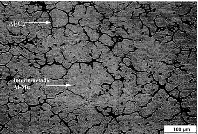
Figure 4.4: Optical micrograph showing microstructure o f alloy AMC501 squeeze cast under 3 M Pa... 75
Figure 4.5: Optical micrograph showing microstructure o f alloy AMC501 squeeze cast under 10 M Pa... 76
Figure 4.6: Optical micrograph showing microsturcture o f alloy AMC501 squeeze cast under 30 M Pa... 76
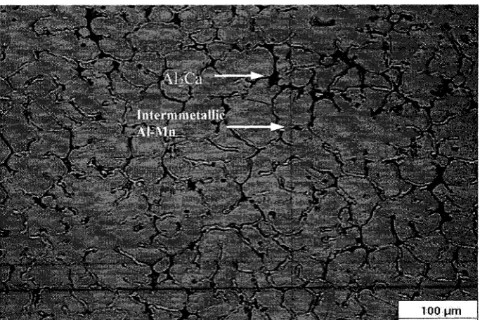
Figure 4.7: Optical micrograph showing microstructure o f alloy AMC501 squeeze cast under 60 M Pa... 77
Figure 4.8: Optical Micrograph showing microstructure o f alloy AMC501 squeeze cast under 90 M Pa... 77
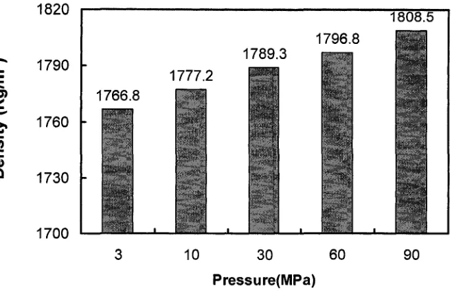
Figure 4.9: Effect o f applied pressures on density...79
Figure 4.10: Porosity versus applied p ressu re... 79
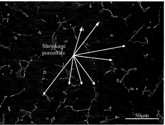
Figure 4.12: Shrinkage porosities in AMC501 cast under 10 M Pa... 80
Figure 4.13: No shrinkage porosities in AMC501 cast under 30 M P a ... 81
Figure 4.14: No shrinkage porosities in AMC501 cast under 60 M P a ... 81
Figure 4.15: Strain stress curves o f AMC501 under 3 and 90 M Pa... 83
Figure 4.16: Effect o f pressure levels on UTS, YS and Elongation o f AMC501 alloy ....84
Figure 4.17: True stress-strain curve o f AMC501 cast under 3 and 90 M P a... 85
Figure 4.18: Strain hardening rate versus strain o f AMC501 cast under 3 and 90MPa....85
Figure 4.19: SEM fractographs o f squeeze cast AMC501 under 90 M Pa...87
Figure 4.20: SEM fractographs o f squeeze cast AMC501 under 3 M P a ... 88
Figure 4.21: Optical micrograph showing crack origin in AMC501 squeeze cast under 3 M Pa...89
Figure 4.22: Optical micrograph showing crack origin in AMC501 squeeze cast under 90 M Pa... 89
Figure 4.23: Optical micrograph showing microstructure o f squeeze cast AM50A under 30 M P a ... 93
Figure 4.24: Optical micrograph showing microstructure o f squeeze cast AMC501 under 30 M P a ... 94
Figure 4.25: Optical micrograph showing microstructure o f squeeze cast AMC502 under 30 M P a ... 94
Figure 4.26: Optical micrograph showing microstructure o f squeeze cast AMC503 under 30 M P a ... 95
Figure 4.29: SEM micrograph showing discontinuous precipitation o f secondary phase in
squeeze cast AM50A under 30 M P a...96
Figure 4.30: Effect o f calcium content on fraction area o f second phase...97
Figure 4.31: SEM micrographs showing microstructure o f squeeze cast AM50A under 30M Pa... 97
Figure 4.32: EDS spectrum from the region marked " J " in Figure 5 .3 1 ...98
Figure 4.33: EDS spectrum from the region marked "K and N " in Figure 5.31... 98
Figure 4.34: EDS spectrum from the region marked " M, L and O " in Figure 5.31... 99
Figure 4.35: SEM micrographs showing microstructure o f squeeze cast AMC502 under 30 M Pa... 99
Figure 4.36: EDS spectrum from the region marked "A" in Figure 4 .3 5... 100
Figure 4.37: EDS spectrum from the region marked "B, F, H and G" in Figure 4.35.... 100
Figure 4.38: EDS spectrum from the region marked "C, D and E" in Figure 5.35...101
Figure 4.39: Location which the EDS maps was taken from A M C 502... 101
Figure 4.40: Distribution o f aluminum in AMC502 ... 102
Figure 4.41: Distribution o f calcium in AM C502...102
Figure 4.42: Distribution o f manganese in A M C502... 103
Figure 4.43: Location which the EDS maps was taken from A M 50A ...103
Figure 4.44: Distribution o f aluminum in A M 50A ... 104
Figure 4.45: Distribution o f manganese in AM 50A... 104
Figure 4.47: Effect o f calcium content on tensile properties o f squeeze cast AM50 alloy
at room temperature...107
Figure 4.48: Al-Ca binary phase diagram... 109
Figure 4.49: Al-Mg binary phase diagram... 109
Figure 4.50: True stress-strain curves for Mg-Al-Ca alloys at room tem perature...111
Figure 4.51: Strain hardening rate versus strain curves for Mg-Al-Ca alloys...I l l Figure 4.52: True stress-strain curves for Mg-Al-Ca alloys at room temperature...115
Figure 4.53: Effect o f calcium content on tensile properties o f squeeze cast AM50 alloy at elevated temperature... 116
Figure 4.54: True stress-strain curves for Mg-Al-Ca alloys at 150 °C...116
Figure 4.55: Strain hardening rate versus strain curves for Mg-Al-Ca alloys... 117
Figure 4.56: SEM fractographs o f squeeze cast A M 50A ...119
Figure 4.57: SEM fractographs o f squeeze cast A M C 501... 120
Figure 4.58: SEM fractographs o f squeeze cast A M C 504...121
Figure 4.59: Optical micrograph showing crack origin in A M 50A ...122
Figure 4.60: Optical micrograph showing crack origin in AM C5 0 4 ...122
Figure 4.61: SEM fractographs o f squeeze cast A M 50A ...124
Figure 4.62: SEM fractographs o f squeeze cast A M 50A ...125
Figure 4.63: Optical micrograph showing crack origin in AMC504 at 150 °C ...126
Figure 4.64: Optical micrograph showing crack origin in AM50A at 150 °C ...126
Figure Ap2.1: Tensile curves o f squeeze cast AMC501 under applied pressure o f 3 MPa at room temperature...150
Figure Ap2.3: Tensile curves o f squeeze cast AMC501 under applied pressure o f
30 MPa at room temperature...153
Figure Ap2.4: Tensile curves o f squeeze cast AMC501 under applied pressure o f
60 MPa at room temperature...154
Figure Ap2.5: Tensile curves o f squeeze cast AMC501 under applied pressure of
90 MPa at room temperature...156
Figure Ap2.6: Tensile curves o f squeeze cast AM50A under applied pressure o f
30 MPa at room temperature...157
Figure Ap2.7: Tensile curves o f squeeze cast AMC502 under applied pressure of
30 MPa at room temperature...159
Figure Ap2.8: Tensile curves o f squeeze cast AMC503 under applied pressure o f
30 MPa at room temperature...160
Figure Ap2.9: Tensile curves o f squeeze cast AMC504 under applied pressure of
30 MPa at room temperature...162
Figure Ap2.10: Tensile curves o f squeeze cast AM50A under applied pressure o f
30 MPa at 150 °C...163
Figure A p2.11: Tensile curves o f squeeze cast AMC501 under applied pressure of
30 MPa at 150°C... 165
Figure Ap2.12: Tensile curves o f squeeze cast AMC502 under applied pressure o f
30 MPa at 150°C ...166
Figure Ap2.13: Tensile curves o f squeeze cast AMC503 under applied pressure o f
Figure Ap2.14: Tensile curves o f squeeze cast AMC504 under applied pressure o f
30 M Pa at 150 °C...169
Figure A p3.1: SEM fractographs o f squeeze cast AMC501 under 3 M Pa... 170
Figure Ap3.2: SEM fractographs o f squeeze cast AMC501 under 90 M Pa... 170
Figure Ap3.3: SEM fractographs o f squeeze cast AM50A under 30 MPa
at room temperature... 171
Figure Ap3.4: SEM fractographs o f squeeze cast AMC501 under 30 MPa
at room temperature... 171
Figure Ap3.5: SEM fractographs o f squeeze cast AMC504 under 30 MPa
at room temperature... 172
Figure Ap3.6: SEM fractographs o f squeeze cast AM50A under 30 MPa at 150 ° C .172
CHAPTER I
INTRODUCTION
1.1 Background
Squeeze casting is a process by which molten metal solidifies under pressure
within closed dies positioned between the plates o f a hydraulic press. The applied
pressure and the instant contact o f the molten metal with the die surface produce a rapid
heat transfer condition that yields a pore-free fine-grain casting with mechanical
properties approaching those o f a wrought product [1-11]. Although squeeze casting is
now the accepted term for this process, squeeze casting also known as liquid pressing
[12], extrusion casting [13], liquid forging [14], pressure crystallization [15], and squeeze
forming [16].
Although squeeze casting and its variants have been used as a commercial process
in the USSR for some time, the process has only recently found commercial applications
in the western industrialised world [2-4].
Squeeze casting has its origin in work by Chernov [17], which in 1878 suggested
that steam pressure might be applied to molten metal during solidification in a permanent
mold. However, the first recorded attempt to study the effect o f pressure on the
solidification behaviour o f liquid metals and alloys was not carried out until 1931 by
Welter [18] on Al-Si alloys. The possibility o f combining traditionally casting and
forging w as initially exam ined in details in the U S S R during the late 19 3 0 ’s, principally
by Plyatskii [13]. After extensive work, the process parameters governing the technique
were successfully resolved, and by the mid 1960’s 150 large batch plants were operating
in 1965, western interest in the process was awakened, which resulted in active research
and commercial production in many countries including the USA, Japan and Britain [2].
The squeeze casting process is easily automated to produce near-net to net-shape
high quality components. Aluminium, magnesium, and copper alloy components are
readily manufactured using this process. Several ferrous components with relatively
simple geometry-for example, nickel hard crusher wheel inserts- have also been
manufactured by squeeze casting processes. Despite the shorter die life for complex
ferrous castings requiring sharp corners within the die or punch (tooling), the process can
be adopted for products where enhanced properties and/or saving in labour or material
costs are desired [1,2].
Squeeze casting is simple and economical, efficient in its use o f raw material, and
has excellent potential for automated operation at high rates o f production. The process
generates the highest mechanical properties attainable in a cast product [2].
M agnesium is a plentiful element, comprising 2.7% o f the earth's crust, one o f the
lightest among all the engineering materials with a density o f 1.74g/Cm3; 35% lighter
than aluminum and over four times lighter than iron or steel. Magnesium is frequently
used as an alloying element in aluminum to improve the corrosion resistance and
machinability. Recent attention has focused on the use o f magnesium alloys for weight
saving in the transportation and aerospace industries, but still keeping the high strength to
weight ratio.
M agnesium alloys meet the demand for a combination o f light weight, good
machinability and handling, high recycling potential, and are designed as engineering
the past decade [19]. To increase the use o f magnesium to further reduce the weight o f
vehicles, the next generation o f magnesium automotive applications needs to be expanded
in a more aggressive sense [19]. One of the potential areas is in the powertrain system
where the operating temperature could approach or exceed 200 °C with the presence o f
cyclic thermal and mechanical loadings. However there is a major limitation on the use o f
magnesium in power train system. This is primarily due to the inadequate creep resistance
and the poor corrosion resistance that the conventional die casting magnesium AM and
AZ alloys inherently provide. Efforts to improve the creep strength o f magnesium die
casting alloys at temperature exceeding 120 °C have resulted in the introduction o f alloy
containing Si, RE, Ca and Sr elements or mixture o f them. These alloying elements form
inter-metallic constituents that stabilize the grain boundaries. In these alloys, Aluminum
must be kept at relatively low levels [20].
Ca is a cheap and light element which can contribute to high temperature
properties [21-25]. Small addition o f calcium significantly improves the creep and stress
resistance o f AM50 [26-28]. The addition o f 1.7% Ca dramatically lowers the creep rate
o f the die-cats AM50 magnesium alloy for about three orders o f magnitude [29, 30].
But the addition o f calcium to magnesium alloy is not trouble free. The addition
o f calcium increases the casting defects such as sinks, solder drag and cracks in high
pressure die casting [31, 32].
Therefore it seems necessary to develop alternative manufacturing processes for
potential high temperature magnesium-aluminium-calcium (Mg-Al-Ca) alloys, such as
squeeze casting. Hence process-related casting defects can be minimized while the
1.2 Objectives of the research
This project is divided into two sections. In an effort to develop a squeeze casting
process for potential high temperature magnesium-aluminium-calcium alloy, the first
objective o f this study was to investigate the effect of applied pressure levels on
microstructure, mechanical properties and soundness o f castings (including porosity and
cracks). The other objective o f this work are to investigate the effect o f calcium contents
on microstructure and tensile properties o f Mg-Al-Ca alloys in room and elevated
temperature for determining Ca role in the squeeze cast alloys.
1.3 Organization of the thesis
This thesis contains six chapters. Chapter 1 has provided a general background o f
squeeze casting. Chapter 2 is the literature review which looks into the process o f squeeze
casting and metallurgical aspect o f magnesium alloys, especially those with high potential
for high temperature applications. The experimental procedures used in this research
work are described in chapter 3. Chapter 4 reports and discusses the results o f the effect
o f pressure levels and calcium contents on microstructure and tensile properties o f Mg-
Al-Ca alloys. The conclusions o f the present study are summarized in chapter 5. Finally,
CHAPTER II
LITERATURE REVIEW
2.1 Squeeze casting
2.1.1 Process description
Squeeze casting has been developed based on the principal o f pressurized
solidification, in which finished castings can be produced in a single process from molten
metal to solid components within reusable dies. As shown in Figure 2.1, squeeze casting
involves several steps:
1- A suitable die set is installed on the bed o f a hydraulic press. The die set is
preheated to the required working temperature. During the heating-up period, the
die set is usually sprayed with a commercial graphite lubricant.
2- A metered quantity o f molten metal is poured into an open female die cavity.
Then, an upper male die or punch is lowered, coming into contact with the liquid
metal.
3- The pressure is applied shortly after molten metal begins to solidify and
maintained until all the molten metal has solidified. The upper punch returns to its
original position and the casting is ejected.
The high pressure applied (typically 50 to 200 MPa) is enough to suppress gas
porosity except in extreme cases, for which standard degassing treatments are used [1-3,
9, 10, 14]. The tendency toward shrinkage porosity is lim ited by using a bare m inim um o f
superheat in the melt during pouring. This is possible in squeeze casting because o f melt
fluidity, is not necessary for die filling. In heavy sections o f the casting, which are
or semi-liquid metal from hot spots into incipient shrinkage pores to prevent pores from
forming. Alloys with wide freezing ranges accommodate this form o f melt movement
very well, resulting in sound castings with a minimum o f applied pressures [1].
Because o f the magnitude o f pressures involved, squeeze casting takes place in metal
dies sufficiently thick to withstand the applied pressures. The dies are usually made from
high quality die steels, which are heated and lubricated [3,4]. Currently H I3 tool steel is
a widely used material for die construction; but generally dies should have good hot
hardness, high temper resistance, adequate toughness, and especially a high degree o f
cleanliness and uniform microstructure [4, 33]. To facilitate release o f the casting, draft
angles are chosen to be 0.5 degrees on external walls o f the die, and 1 to 2 degrees on the
punch surface and on die details around which the casting tends to contract after
solidification [33].
2.1.2 Types of squeeze casting
In general, two different kinds o f squeeze casting techniques, known as “direct”
and “indirect”, have been developed based on different approaches o f metal metering and
metal movement.
2.1.2.1 Direct squeeze casting
The direct squeeze casting technique is characterized by a direct pressure imposed
onto the casting without any gating system as illustrated in Figure 2.1. The pressure is
applied in two stages to prevent the melt from spraying out through the necessary gap
solidifying material are closed [7]. Since the pressure is directly applied to the entire
surface o f the molten metal during solidification, this technique gives fully densified
components and extremely fast heat transfer, which yields fine grain structure [1-3, 9,
10]. It means that the cycle times for squeeze castings are generally much shorter than
those for either gravity or low pressure die castings. For instance it has been reported that
a cycle time o f only two minutes is required for the production o f an aluminium alloy car
wheel, in comparison with six minutes for low pressure process [3]. As a result o f high
heat transfer, enhanced mechanical properties are attained.
The process is mainly suited to chunky components having a small aspect ratio i.e.
the width and height o f the casting are o f similar dimensions [2], The major advantages o f
direct squeeze casting over other processes can be itemized as follows [5, 34]:
Material having neither gas porosity nor shrinkage porosity is produced;
No feeder or risers are required and therefore no metal wastage occurs;
- The inherent “castability” o f the alloy is o f little or no concern since the applied
pressure obviates the need for the customary high fluidity, which enables both
common casting and wrought alloys to be squeeze cast to finished shape;
Control o f the microstructure is possible solely by control o f the dominant process
parameters such as the pouring temperature and mould temperature;
- Because there are no internal (or external) defects on a properly produced squeeze
cast component; costly post-solidification examination by non-destructive testing
techniques is o f very limited value;
Squeeze castings can have mechanical properties as good as, and in some cases
Squeeze castings provide the most effective and efficient route to produce near-
net-shape composite components for engineering applications.
Punch
■ p i— --- runcn ^ m
Cruci bl e — \ *
g-««--- Ejector 1
I
(c) (d)
Figure 2.1: Schematic diagram o f direct squeeze casting process[6]
a) stepl, preheated, lubricating tooling ;
b) step2, transfer melt into die cavity;
c) step3, solidify m elt under pressure; and
2.1.2.2 Indirect squeeze casting
In the indirect technique as shown in Figure 2.2, the pressure is exerted on a gate,
which transmits the load to the component. This technique is really a hybrid process
between low pressure die casting and high pressure die casting. The melt is pushed
through a relatively large feeder compared to pressure die casting [7, 9 and 10]. The gate
velocity o f the melt is usually between 0.5 m/sec [7] and 3 m/sec [10] compared to 30
m/sec for pressure die casting. This requires a gate three to five times larger than in
conventional high pressure die casting [2], The low flow rate ensures a controlled filling
o f the mould without trapping air [7, 9 and 10]. Due to the fact that the pressure is
imposed at a distance from the component, it is difficult to maintain high pressure on the
component throughout its solidifying and cooling periods. This indicates that it is difficult
to cast long freezing range alloys with the indirect technique. Also, metal yield is much
lower than that achievable with direct squeeze casting owing to the necessity o f using a
gating system. The advantage o f the indirect technique is that, due to presence o f a gating
system, a highly accurate external metering system is not necessary. Variations in metal
volume are adjusted in the gate. Although it seems that the direct squeeze cast offers
more opportunities for a wide range o f alloys for the production o f high strength, full
integrity metal casting and metal matrix composite components but more indirect squeeze
casting machines presently is in operation than direct. This is probably because the
indirect process has been successfully commercialized. To achieve a sound structure the
aspect ratio is usually kept below 5:1 [2].
The m ajor advantage o f indirect squeeze casting is that, because the casting forms
direct process. Thus, the use o f a highly accurate external metering system is not
necessary [3]. The slow filling o f the die enables the use o f lost cores, which in the case
o f pressure die casting are often broken or washed away [7]. In practice, indirect squeeze
casting has two disadvantages [3,5]:
Material utilisation is inefficient and very much less than the high levels
achievable with direct squeeze casting because o f the necessity o f using a runner
and gating system [5, 7]. The biscuit and runners have to be machined o ff the
casting and internally recycled in the same manner as high pressure die casting
practice.
Because o f the complexities o f the necessary runner systems and due to the fact
that the external pressure on the metal is applied at a great distance from the
casting, it follows that it is difficult to maintain a high pressure on the casting
throughout its freezing and cooling periods. This means that long freezing range
alloys cannot be cast by indirect squeeze casting, which limits the process to
conventional casting alloys. The high strength, ‘wrought’ aerospace alloys are
extremely difficult, if not impossible, to cast defect-free using the indirect squeeze
casting process.
O f the two philosophies for squeeze casting (direct and indirect), it appears that
the direct process offers more opportunities for utilisation o f a wide range o f alloys for
production o f high strength, full integrity castings, and metal matrix composite
Charge shot
Dock
Fill
Squeeze
Figure 2.2: Schematic diagram showing the operation o f a typical vertical injection
indirect squeeze casting machine [4].
2.1.3 Process Parameters
There are a number o f variables that are generally controlled for the soundness
and quality o f the castings. The variable ranges discussed in the following sections may
differ with alloy system and part geometry being squeeze cast.
2.1.3.1 Alloy composition
The most important process parameter is the alloy itself. The composition and
physical characteristics o f the alloy are o f paramount importance due to their direct
effects on the die life. These include the melting temperature and thermal conductivity o f
the alloy together with the combined effect o f the heat-transfer coefficient and soldering
onto the die material. Furthermore, the alloy dictates the selection o f casting parameters
2.1.3.2 Melt volume and quality
In the direct process, due to lack o f runners and gating to accommodate any
excess metal, precision control o f the metal volume is required when filling the die cavity,
which ensures dimensional control [1, 2]. However this has appeared to be difficult even
by using automatic ladling or commercial metering pumps, especially for small
components or multi-dies. A technique suggested to solve the problem is to pour excess
metal into the die and allowing the component to be oversized in a non-critical direction
or to include an overflow system [2]. In addition for the same reason, that is, no gating
system, more attention has to be paid to the melt quality, in terms o f dross, in the direct
than in the indirect processes. However, in both direct and indirect squeeze castings, the
presence o f absorbed gases in the melt is less critical than that in any other casting
processes, owing to the nature o f squeeze casting where the imposed pressure is usually
sufficiently high to suppress gas evolution and retain gases solution.
2.1.3.3 Pouring temperature
Pouring temperature depends on several factors, such as liquidus temperatures,
freezing ranges o f metals and die complexity. Normally, high superheat above the
liquidus is required for narrow freezing range metals due to their relatively fast
solidification rates. In general, a low pouring temperature for wide freezing range alloys
is more effective in yielding good metallurgical quality [3, 33]. However, too low pouring
temperatures can result in the insufficient fluidity, which leads to incomplete die fill and
cold laps. On the other hand, too high pouring temperature might cause extrusion o f
Also shrinkage porosity might occur in thick sections o f the casting. A high pouring
temperature can reduce the die life significantly [35].
At pouring temperatures above the liquidus temperature, columnar grain structure is
reported in Al-Si alloys; grains are equiaxed when poured at the equilibrium temperature.
This refinement is attributed to the under-cooling that is a result o f increasing the liquidus
temperature with pressure, via the Clapeyron effect [11].
Ha [36] reported an equiaxed grain structure for squeeze cast AZ91 Mg poured at
680 °C and an ingot-type structure for squeeze castings at 730 °C. Rozak [20] observed a
finer equiaxed grain size in squeezed cast AZ91 Mg at 735 °C than at 700 °C, attributed to
changes in the inoculation efficiency.
For aluminium alloys, the casting temperature may range between 10 to 100 °C
above liquidus temperatures, with the lower limit applicable to alloy like 7075 and A390
aluminum that have extended freezing ranges, and the upper limit to narrow freezing
range alloy such as 3003 and A413 aluminium [33]. The value for magnesium may be
higher than aluminium due to a lower specific heat capacity [2]. Superheats varying from
30-140 °C have been used in the previous study for magnesium alloys [6].
2.1.3.4 Tooling temperature
Operating die temperatures need to strike a balance between the need for
sufficient heat to prevent premature solidification o f metals, thermal fatigue in the
tooling, and cold laps on the surface o f the casting. There is a tendency for welding to
occur between the casting and the mould if the die temperature is too high. Ranging from
200 to 300 °C is normally used [1-4, 6]. The lower range is more suitable for thick section
Temperatures above 300 °C are not recommended for aluminium alloys. Although it has
been reported that, although a low die temperature around 150 °C can result in an
equaxied grain structure for magnesium alloy AZ91D, the detailed values for magnesium
alloys are still unknown [36]. To provide a stable die temperature during production,
water or oil cooling line in the die may be necessary [2],
The punch temperature is often kept 15 to 30 °C below the die temperature to
maintain sufficient clearance between them for adequate venting. Excess punch-to-die
clearance allows molten metal to be extruded between them, and therefore eroding the
surface o f die [1].
2.1.3.5 Time delay and temperature for pressure application
Time delay is the duration between the actual pouring o f the metal and the instant
at which the punch contacts the molten pool and starts the pressurization. Because
increased pouring temperatures may required to fill these sections adequately upon
pouring, a time delay allows for cooling o f the molten pool before closing o f the dies to
avoid shrink porosity [1]. This time varies depending on melt temperature and component
geometry. Times differ greatly but generally range from a few seconds for small ferrous
components to approximately one minute for large aluminium alloy components [2]. For
magnesium alloys, the effect o f this time delay on the properties and structures o f the
castings is still unknown and needs to be investigated [6].
There is no universal agreement regarding the temperature for pressure
application, i.e. if the metal should be fully liquid or partially solid. Bidulya [38] and
Weinberg [39] suggested that pressure should be applied when the metal is near the “zero
properties. However, the melt should be mainly liquid according to Williams et al [34] for
squeeze casting to be fully effective.
2.1.3.6 Pressure level
The density o f the squeeze casting is increased by applied pressures exerted on
solidifying metal [10, 14]. Pressure levels o f 50 to 200 MPa are normally used as 70 MPa
is generally applied, depending on the part geometry and required mechanical properties.
The improvement in mechanical properties with pressure is expected to level off as
porosity is eliminated and maximum structural refinement occurs; e.g., grain size
approaches minimum. Hence there is an optimum pressure for each o f the systems after
which no additional advantages in mechanical properties obtained [1 ,4 , 14, 40 and 41],
Factors affecting the pressure are: [33]
flow stress o f the alloy near its freezing temperature;
the growth morphology o f the alloy crystallites; and
the freezing range o f the alloy.
2.1.3.7 Pressure duration
Pressure duration varying from 30 to 120 second has been found to be satisfactory
for castings weighing 9 Kg (20Lb) [1], Franklin and Das [42] recommend pressurization
time o f about 1 second per mm o f the section thickness. However, the pressure duration is
dependent on part geometry, alloy type and heat transfer condition [2]. As the time of
pressure application is increased, finer dendrite is produced [14], However applied
pressure after complete solidification does not contribute any property enhancements and
solidification is completed, since slightly longer times may be used to avoid hot tearing.
Prolong holding times provide little benefit, and may cause wall cracking or problems
with punch redrawal, due to thermal contraction o f the casting on the rigid punch [2].
2.1.3.8 Lubrication
Lubrication for aluminium, magnesium, and copper alloys, a good grade o f
colloidal graphite spray lubricant has proved satisfactory when sprayed on the warm dies
prior to casting. Excess build-up on narrow webs and fin areas should be avoided where
vent holes or slots are used [1, 2, 4]. Care must be taken to prevent plugging these vents.
At the pressure applied during squeeze casting, the coat may strip from the die surface
and cause surface contamination in the component. Limiting the lubricant thickness to 50
microns, should prevent this to occur [2].
For ferrous castings, ceramic-type coatings are required to prevent welding
between the casting and the metal die surfaces [1, 33].
2.1.3.9 Press speed
Press speed in most practical purposes, a punch impact speed o f 0.5m/sec may be
used without detrimental effects. In the situation where there is a large distance between
punch and die, a two speed action may be used, i.e., a rapid approach o f the punch to the
metal surface followed by a slower impact speed.
2.1.3.10 Ingate size (indirect squeeze casting)
The ingate size for indirect squeeze casting is an important consideration since it
solidifying casting. The volume o f metal entering the die cavity has to be sufficient to fill
the cavity before localized solidification occurs. This is best accomplished with a larger
ingate to attain rapid filling without excessive velocity and the inertial type o f flow that
occurs at high metal velocities. The fan type o f ingate helps to accomplish this rapid fill
without high velocity [9]. The velocity o f the melt at ingates is usually between 0.5 m/sec
[7] to 3 m/sec [10] compared to 30 m/s for pressure die casting [7]. The low flow rate
ensures a controlled filling o f the mould without trapping air with a proper venting [7, 9
and 10].
2.1.4 Effect of Applied pressure
2.1.4.1 Reduction of porosity
Pressure applied to liquid metal prior to and during solidification tends to reduce
or eliminate the gas related porosity. Increased pressure increases the solubility o f gases
in the melt. These gases do not evolve during solidification, due to the difficulties in
nucleation o f bubbles against the pressure [2]. For the other main cause o f void related
defects, solidification shrinkage, the effect o f pressure is to force feed the liquid or semi
solid metal into the voids, producing a fully dense material [2].
2.1.4.2 Equilibrium diagrams
Equilibrium phase diagrams depict conditions of slow cooling rates under
atmospheric pressure. However, these are not the conditions encountered during squeeze
casting. The application o f pressure causes the melting point o f most alloys to increase in
AT _ Tf(Vi- V.) AP “ AHr
where AHf is latent heat o f fusion, Vs and V] are specific volume o f solid and liquid
phases, Tf is melting temperature at atmospheric pressure, AT and AP are the variation o f
temperature and pressure, respectively.
The majority o f metals show a rise o f 2-6 °C for every 100 MPa o f external
pressure applied [43]. For pure magnesium, Sekhar [44] calculated dT/dP which is about
0.0647 °C/MPa. Such change in freezing temperature is expected due to reduction in
interatomic distance with increasing pressure and thus restriction o f atomic movement,
which is prerequisite for melting/freezing [4], The inter-solubility o f constituent elements
together with the solubility o f impurity and trace elements is also expected to increase
with pressure [4].
Pressure application also distorts phase diagrams. Figures 2.3 and 2.4 illustrate the
distortion o f Mg-Al and Al-Si phase diagrams due to pressure application and rapid
cooling rates. W hen the melting point o f a component in an alloy is changed by pressures,
the eutectic point is shifted in the direction o f higher concentrations o f the component
whose melting point is least affected [45]. In the case o f Al-Si alloys (Figure 2.3), it
moves towards the higher silicon content [46], while in Mg-Al alloys (Figure 2.4), the
eutectic moves towards the Mg concentration [2], Lipchin [47] and Taha et al [48]
reported that the solubility o f silicon in aluminium increased by squeeze casting. The
volume fraction o f silicon in an aluminium dendrite increased from 3 to 7.8% with an
binary Al-Si alloys o f compositions 7% and 14% squeeze cast at 150 MPa have indicated
an upward movement o f the liquidus and eutectic temperatures o f 9 K and 2.25 K
respectively at a pressure o f -1 5 0 MPa [3, 4].
2.1.4.3 Reduction of grain size
The effect o f solidification under pressure on grain size can be illustrated by
reference to Figure 2.4. Alloy X is well above the liquidus line at T1 at atmospheric
pressure. The application o f pressure causes the liquidus line to move (dotted line) but it
still is below the T l, and the melt does not start to solidify until the temperature has
reached the new liquidus line. Nucleation and growth processes commence at the new
liquidus line, but without significant grain refinement. If, however, the initial alloy
temperature is at T2 when pressure is applied, the liquidus line moves above this point
and super-cooling occurs. The grain refining effect is proportional to the degree o f under
cooling, and a true squeeze casting consists o f fine equiaxed grains as a result o f correct
pressurisation applied at the appropriate time. Further, the dendrite arm spacing becomes
smaller, constituent particles tends to remain small and a more homogeneous distribution
o f structural components takes place [14, 42], Also the applied pressure has a marked
effect on heat transfer during the solidification o f the castings (which will be discussed in
700
500
CD
a
E H 300
Mg 10 £0 30 40
A lum inium c o n te n t (%)
Figure 2.3: Deviation from equilibrium conditions in the Mg-Al phase diagram due to
high applied pressure [44].
165;
m-**. Si
2.1.5 Effect of applied pressure on microstructure
The effects o f squeeze casting on solidification are manifested in the
microstructural refinements: grain structure, porosity, segregation, and secondary phases.
In addition to the densification achieved, there are several reasons why squeeze casting
produces casting with superior properties. The applied pressure has a marked effect on
heat transfer during the solidification o f the castings. Due to contraction o f most metals
and thermal expansion o f the mold during solidification, the detachment o f the casting
from the die wall takes place once the initial solid shell o f the casting has sufficient
strength to hold the remaining molten metal. Consequently, an air gap is formed between
the die walls and casting, which considerably increases resistance to heat transfer. In
squeeze casting, the applied pressure on the casting forces the initial solid shell to remain
in contact with the die for a certain period o f time before any detachment could occur. If
the applied pressure is sufficiently high, the intimate metal-die contact can be maintained
via the plastic deformation o f the casting throughout solidification. This leads to very fast
heat transfer, high cooling rates and an increase in casting temperature gradients [4, 6].
Murthy and Satyanarayan [49] found an increase in the cooling rate from 6 K/sec in
permanent mould casting to 300 K/sec in squeeze casting. Due to higher cooling rate in
squeeze casting, dendrite arm spacing is much finer in comparison with that resulting
from other casting process [9, 14]. The study by Fujii et al [50] on squeeze casting o f an
aluminium alloy indicates that the solidification time is only a h alf the time in gravity
castings; the heat transfer coefficient is four times higher than that in gravity castings; and
temperature gradients in the casting increase with applied pressure. Even moderately
tenfold increase in heat transfer rate over permanent mold casting. This results in
relatively fine grains in the casting. Fine grain size is also promoted by the large number
o f nuclei formed because o f the low pouring temperature and the elevated pressure [1 ,2 ,
and 4]. Furthermore, because die filling in squeeze casting does not require high melt
fluidity, a number o f wrought alloys can be squeeze cast. Again, pressurized solidification
with rapid heat transfer tends to minimize the segregation that wrought alloys are usually
prone to [2, 34].
The high solidification rate also distorts the equilibrium phase diagram by
modifying the solubility o f solute atoms. Lipchin observed that pressure during
solidification increase the solubility o f the second component during solidification. Only
in the Al-Mg, Al-Zn, and Mg-Al systems does the solid solubility o f the second phase
decreased with an increase in applied pressure o f squeeze casting [47],
2.1.5.1 Aluminum alloys
In the case o f Al-Si alloys, fibrous silicon is the likely morphology. A typical
squeeze cast microstructure o f LM24 Al-Si alloys (Al- 8.5wt.%Si-3.5wt.%Cu) is shown
in Figure 2.5, together with conventionally cast to highlight the differences in silicon
morphology and grain structure [4],
Reddy and Murthy [14] reported a low pouring temperature, high specific pressure
and minimum dwell time results in high densities, fine dendrites arm spacing, isotropic
microstructure o f squeeze castings compared to those o f sand or metal mould castings.
Pressurised solidification modifies eutectic silicon in aluminium-silicon alloys.
Taha et al [48] reports a decrease in the size and number o f eutectic silicon particles with
A356 Al alloy was a globular shape; but the shape was elongated when sand cast [51].
Sobczak [52] also reportd a globular shape o f eutectic silicon in squeeze cast Al-12%Si
alloy without modifiers after a 3-hr, 300 °C heat treatment.
Murthy [49] reported that, in case o f aluminum-silicon alloys, pressure
solidification leads to (a) an increase in volume fraction o f a-phase with an increase in
pressure, (b) fragmentation o f primary dendrites, (c) decrease in the volume fraction o f
eutectic, and (d) refinement o f |3-silicon o f the eutectic.
Balan [53] showed that microstrucre refinement takes place when pressure is
applied to the solidifying metal. The primary dendrites become finer for aluminum LM6
alloy (Al-11.5wt.%Si) with increasing pressure. The volume fraction o f the primary
dendrites increases from 34.0 to 39.8% when the pressure is increased from 0 to 75 MPa.
The dendrite arm spacing similarly decreased from 30 to 5 pm over the same pressure
range.
Chemical grain refinement has no significant effect on squeeze casting. However,
by the addition o f modifier, i.e. in an Al-Si alloy, uniform and much smaller silicon
particles can be obtained [2],
2.1.5.2 Magnesium alloys
Yong et al [41] reported a sixfold reduction in cell size for RZ5 (Zn4.2%, RE 1%,
Zr 0.7%) magnesium alloy as the pressure increases from 0.1 to 60 MPa. The reduction in
cell size was attributed to the intimate contact between the melt and die wall that
Figure 2.5: Optical micrograph showing the as cast structure o f LM24 Al-Si alloy [4]
2.1.6 Mechanical properties
Squeeze casting is amenable to the use o f a very wide range o f alloys. Alloys that
respond to heat treatment can quite successfully be put through the necessary solution
treatment and age hardening.
It should be noted that the squeeze cast properties are superior in all respects to
those given by conventional casting processes. The proof stresses are improved by
squeeze casting, and o f particular significance is marked improvement in the elongation
to failure [2, 4, and 40]. In general, the fine structure and superior mechanical properties
o f squeeze casting components are due to the following factors: (i) changes in under
cooling o f the molten alloy, (ii) changes in the composition and percentages o f the
forming phases o f the solidifying alloy, (iii) changes in the heat transfer coefficient
between the metallic mould and solidifying alloy, and (iv) changes in the density o f the
alloy due to reduction o f porosity [4]. These improvements reflect both the fine-grained
structure and more importantly the elimination o f microporosity in the squeeze cast
material. In general, a squeeze cast component compares extremely well forgings. In the
most cases, there is a good comparison between the isotropic squeeze cast property and
the longitudinal forging property [34].
The mechanical properties improvement with pressure is expected to level off as
porosity is eliminated and maximum structural refinement occurs; e.g., grain size
approaches minimum. The increase in strength and ductility beyond these refinements
must occur via refinement at the substructural level, e.g., at higher dislocation densities
with increasing squeeze cast pressures. Lipchin and Bykov [43] observe higher
2.1.6.1 Aluminum alloys
Squeeze cast commercial Al alloys are assessed and compared with sand cast
gravity die cast, and die forged material o f the same composition by Yue and Chadwick
[5]. Table 2.1 gives typical mechanical properties for Al-Si casting alloys. Tremendous
improvements in properties can be achieved with fully heat treated squeeze castings. For
instance, the cheap LM24 alloy (Al-8.5wt.%Si-3.5wt.%Cu) can provide better mechanical
strength than the more expensive LM25 (Al-7wt.%Si -0.3wt.%Mg) and A357 (Al-
7wt.%Si-0.5wt.%Mg) alloys when squeeze cast and fully heat treated, However the
elongation shows the opposite [5]. For LM24 (Al-8.5wt.%Si-3.5wt.%Cu) in particular,
which is normally considered to be non-heat treatable, the fully heat treated squeeze cast
material exhibits a 0.2% proof stress three times higher and ultimate tensile strength
(UTS) twice as high as the specified standard requirements [3]. Using the squeeze casting
technique, the usually deleterious iron aluminide crystals do not grow into massive plate
like forms but remain very small and uniformly distributed throughout the matrix and
hence do not exhibit their usual embrittling effects [3, 5, and 34].
Murthy [49] reported an UTS increase from 157 to 226 MPa while elongation
values increased from 8 to 18 percent for LM6 (Al-11.5wt.%Si) as the pressure increase
from 41.2 to 247.2 MPa.
Balan et al [53] studied the effect o f applied pressure (0-75 Mpa) on LM6 Al-Si
alloy (Al-11.5wt.%Si) and reported an increase o f about 3.4% in density, 63% in UTS,
2.6% in percentage elongation and 50% in hardness with increasing applied pressures.
refinement o f the primary a-phase and modification o f the silicon phase [53]. Similar
results were obtained for pure aluminium [54].
Table 2.1 Typical mechnaincal properties o f commercial Al-Si alloys cast by different
Process [5],
Alloy 0.02% PS [MPa] UTS [MPa] Elongation [%]
A357 Typical chill cast (FHT) 248 313 7
Squeeze cast (FHT) 283 347 9.3
LM24 Minimum requirement 100 180 1.5
Typical chill cast 110 200 2
Squeeze cast(as cast) 126 233 2.7
Squeeze cast(FHT) 330 368 2
LM25 Typical chill cast (as cast) 90 180 5
Squeeze cast (as cast) 104 214 5.3
Typical chill cast (FHT) 240 310 3
Squeeze cast (FHT) 274 331 7
FHT = fully heat treatment
Das et al [55] showed when Al-4.5wt.%Cu and Al-3.75wt.%Mg were squeezed
cast under a pressure o f 188 MPa, the UTS and percent o f elongation increased 50% and
128% respectively for Al-4.5wt.%Cu and 38% and 138% for Al-3.75wt.%Mg, in
comparison with the gravity die cast pressure. In addition to grain refinement and
freedom from porosity, the improvement in the tensile properties o f squeeze cast
CuAl2 and the disappreance o f the Cu-rich layer around a-Al, which are directly related to
the influence o f pressures and cooling rates on phase diagram. For Al-3.75wt.%Mg alloy,
the absence o f p constituent, Mg2Al3, which usually is present in sand casting and gravity
die casting, is responsible for tensile properties improvement.
The dynamic properties o f squeeze cast alloys are also superior to conventionally
cast material. For example LM24 (Al-8.5wt.%Si-3.5wt.%Cu) in its squeeze cast and fully
heat treated condition exhibit better fatigue behaviour than the more expensive high
purity alloy as shown in Figure 2.6. This superior behaviour is again due to a combination
o f the absence o f large plates o f embrittling (Fe Al Si) compounds, the refinement o f the
primary and eutectic constituents and the total absence o f porosity [3].
The dynamic and static properties given above were obtained on direct squeeze
cast material. The properties o f the direct squeeze castings are 25-30% greater than those
o f the indirect squeeze castings. These differences are due, presumably, to the greater
refinement o f the microstructure in the direct squeeze casting alloy and to the total
absence o f porosity in the direct squeeze cast alloy [3].
Das et al [55] showed the fatigue life o f the Al-4.5wt.%Cu alloy has an
improvement o f 75% over the sand cast alloy and the Al-3.75wt.%Mg showed a 30%
improvement on the sand cast alloy.
It has been observed that squeezed cast and fully heat treated high strength
aluminium alloys (wrought alloys) exhibit mechanical properties between those o f the
longitudinal (L) and short transverse (ST) properties o f wrought material. Unlike the
direct chill (DC) cast material in which the grain structure is not fully controllable,
Table 2.2. This is due to the fine grain micro-structure and thereby the isotropic yielding
behaviour [2, 3, and 5], Hashemi et al [40] reported the tensile properties o f heat treated
squeeze cast specimens Al-Zn approaches those o f wrought aluminium alloys obtained by
other processes.
■ 5and cost 357
* Chill cos! 357
o Squeeze cost IM25+I.25 Co
• Squeeze c<*d 357*
*- Squeeze cos! IM24
*10*
10*
to 5
MJ*
107
10^
N c y d t*
Figure 2.6: Fatigue behaviour o f some aluminum alloys cast by different techniques [3].
Table 2.2 Comparison o f tensile properties o f fine grained squeeze cast Al-4.5%Cu with
wrought alloy o f similar composition [2].
A lloy 0.02% PS [MPa] UTS [MPa] Elongation[%]
Al-Cu4.5% Squeeze cast (FHT) 184 346 22
2025 W rought properties 225 400 19
2.1.6.2 Magnesium Alloys
Rozak [37] compared the tensile properties o f squeeze cast AZ91 magnesium and
A356 aluminium alloys with those o f the permanent mold cast alloys. AZ91 is one o f the
most common magnesium casting alloys, which contains~9% Aluminium and ~1% Zinc.
The samples were squeeze cast with 138 MPa pressure, heat treated to a T6 condition as
shown in Table 2.3 [11]. The increase in tensile properties is due to highly refined
structure.
Table 2.3 Tensile properties o f cast A356 and AZ91D [11].
Alloy Casting condition
Yield strength
(MPa)
Tensile strength
(MPa)
Elongation
(%)
A356 Squeeze 248 290 5.7
A356 Permanent mold 206 282 10
AZ91D Squeeze 144 303 9.7
AZ91D Permanent mold 124 262 6.2
The variation in properties o f AZ91 in the as cast and in the fully heat treated
condition for sand, gravity die casting and squeeze cast materials is shown in Figures 2.7
and 2.8. The squeeze cast alloy shows the highest value o f ultimate tensile strength, 0.2%
proof stress and elongation-to-failure.
A full heat treatment increases the ultimate tensile strength o f the squeeze cast
material from 200 to 260 MPa with an associated decrease o f elongation o f only 1% [5].
![Figure 2.1: Schematic diagram of direct squeeze casting process[6]](https://thumb-us.123doks.com/thumbv2/123dok_us/1480609.1181208/27.612.186.449.143.516/figure-schematic-diagram-direct-squeeze-casting-process.webp)