20th International Conference on Structural Mechanics in Reactor Technology (SMiRT 20) Espoo, Finland, August 9-14, 2009 SMiRT 20- Division II, Paper 1803
Fracture Mechanics Evaluation of Similar and Dissimilar Welded Fracture
Specimens under Plane-strain
I.A. Khan, V. Bhasin, J. Chattopadhyay, K.K. Vaze, A.K. Ghosh, H.S. Kushwaha
Reactor Safety Division, Bhabha Atomic Research Centre, Mumbai-85, India, e-mail: imran@barc.gov.in
Keywords: Plane-strain, dissimilar welds, plastic η-factor, modified upper bound approach.
1
ABSTRACT
The classical upper bound approach of limit analysis is based on assumption of rigid blocks of deformation that moves between the lines of tangential displacement discontinuity. This assumption leads to considerable simplification but often at cost of higher estimates of the actual load. Moreover, in many cases, it does not give a correct shape of the plastic field. In order to overcome these limitations a Modified Upper Bound approach (MUB) was proposed by Khan and Ghosh (2007). The proposed approach is basically an energetic approach but unlike the classical upper bound approach it is capable of including the presence of statically governed stress field (Khan et al., 2008). In this article various applications of this recently proposed MUB approach in the area of fracture mechanics evaluation of similar and dissimilar welded fracture specimens are discussed. The proposed theoretical solutions were confirmed by detailed elastic-plastic finite element (FE) analysis. Good agreement was found between proposed solutions and the results obtained from FE analysis.
2
INTRODUCTION
It has been widely accepted that defects in welds occur typically as a result of welding process itself or sometimes they may get initiated during service as a result of interaction between applied stresses and service conditions. Typically, a welded joint is heterogeneous both in mechanical properties (that affect deformation behaviour) and in microstructure (that causes variation in mechanical properties such as toughness and stress-strain properties). The effect of microstructure on toughness etc. has already been studied in past, however, an equally important effect that has attracted attention recently is the so called “Mismatch effect” which considers the effect of mechanical heterogeneity on fracture mechanics parameters (Schwalbe et al., 2004). In this work mechanical heterogeneity of weld is considered. The weld configuration investigated is restricted to simple strip model. Moreover, only deeply cracked specimens under plane-strain conditions were considered. Both similar and dissimilar welded fracture specimens were analysed (see fig. 1). It may be emphasised that the mismatch effect is not only dependent on the mismatch factor M (ratio of yield strength of weld material to yield strength of base material), but is also a function of geometrical parameters, mainly of weld slenderness ratio ψ, distance of crack tip/front from the nearest interface and plate thickness for 3-D problems. The assessment of severity of crack-like flaws requires information about limit load, crack tip stresses and crack driving force like the J-integral.
thus, a systematic study of crack-tip stresses would require enormous FE computations. Keeping in view these considerations it was felt that efforts should be made to develop a theoretical approach well suitable to analyse strength mismatch welds.
The classical upper bound approach of limit analysis is based on the assumption of rigid blocks of
deformation that moves between lines of tangential displacement discontinuity (Johnson and Mellor, 1973). As a result of this assumption, the presence of statically governed stress field cannot be incorporated in the solution. Although this assumption leads to considerable simplification but often at cost of higher estimate of the actual load. To overcome this limitation a Modified Upper Bound (MUB) approach was proposed by Khan and Ghosh (2007). Subsequently a rigorous mathematical basis of this load bounding technique was established by Khan et al. (2008) where it was demonstrated that the method (MUB) is actually a new form of already existing extremum/work principle. The equivalence of this new form of work principle, that is, MUB with the classical SLF analysis, for a homogeneous rigid-plastic body in plane strain, was established. For the case of standard (homogeneous) fracture mechanics specimens like single edge cracked specimen subjected to pure bending SE(PB), three-point bend specimen SE(B) and compact tension specimen C(T), limit load, crack-tip stresses and plastic η-factor were obtained. As a novel application of the proposed method, single-edge-cracked specimen under combined bending and tensile load was analysed and a completely analytical formulation for yield locus for the entire range of tensile and bending load was proposed (Khan et. al., 2008).
In this article analytical solutions for limit load and plastic η-factor for both similar and dissimilar welded/bimetallic fracture specimens are presented. The proposed theoretical solutions were confirmed by detailed elastic-plastic FE analysis. Good agreement was found between proposed solutions and the results obtained from FE analysis.
3 MODIFIED UPPER BOUND APPROACH
The general expression of classical upper bound approach is as follows (Kachanov, 1971)
* * * *
p
i i ij ij p
s V s
T v dS# ! d" dV+ kv dS
$
$
$
(1)Here ν* denotes the tangential displacement increment discontinuity on a surface Sp for the kinematically admissible velocity field vi*, k the shear yield strength, Ti the traction acting on the surface S,
d ij*the assumed rate of plastic strain increments as derivable from vi*in the usual way and σij*is a stress field, not necessarily statically admissible, derivable by way of the concept of the plastic potential from the strain increment field d ij
*
. The assumption, which is often invoked to simplify the analysis, is to consider the rigid mode of deformation, that is, the material is assumed to move in rigid blocks separated by lines of
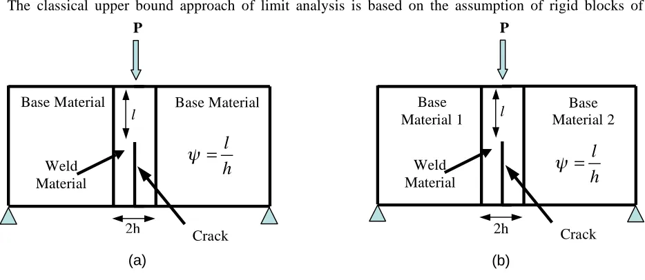
Fig. 1: Schematic of (a) similar and (b) dissimilar welded SE(B) specimen with weld centre crack. (a)
Crack Base Material Base Material
Weld Material
2h
l Material 2 Base
(b)
Crack Base
Material 1
Weld Material
l
2h
l
h
!
=
l
h
!
=
Fig. 2: A typical FE mesh used in present investigation. tangential displacement discontinuity. Under this condition d ij
*
becomes zero and Johnson and Mellor (1973) sets the first integral of the right hand side of eq. (1) to zero. The velocity discontinuity ν* now refers to any fictitious mode of deformation assumed in the problem. This method requires no integration, in plane strain cases, as the tangential component of velocity discontinuity ν* is constant along any assumed deformation path. This results in considerable simplification and useful upper bounds can be easily obtained. Unfortunately, as a result of this simplifying assumption, particularly for the problems involving predominant bending loads, this upper bound approach provides (unacceptable) higher estimates of the limit loads. Thus, despite its efficiency the use of this upper bound analysis is quite restricted. To overcome this limitation Khan et al. (2008) assumed that a rigid plastic body actually comprises of two distinct regions viz., Region I consisting of a set of volumes, say Vm (m=1, 2, 3…), comprising of rigid blocks of materials separated by surfaces of tangential displacement discontinuity (similar to the assumption made in classical upper bound approach) and Region II consisting of another set of volumes say Vn (n=1, 2, 3…), having deforming zone. They further assumed that the stress distribution in deforming zone is such that it satisfies differential equations of equilibrium at each and every point in this plastically deformed zone. However, neither information regarding the state of stress in region I was required nor it was necessary to prove that the stress distribution there satisfies the equilibrium equations. With these assumptions, Khan et al. (2008) has proposed following expression of modified upper bound (MUB) approach.
* *
* 1
Dm n
i m ij j n
i
s s S
T dS kv dS n dS
v !
=
"
+"
#
#
#
(2)If the assumption of rigid mode of deformation (Johnson & Mellor, 1973) is invoked over the whole body then second integral term of eq. (2) becomes zero. With this assumption eq. (2) would reduce to the conventional form of upper bound theorem that is widely used in load bounding estimates.
4.0 FINITE ELEMENT ANALYSIS
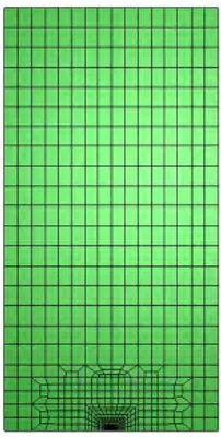
In order to validate the proposed theoretical solutions, limit analyses of similar and dissimilar welded SE(PB), SE(B) and C(T) specimens were performed. For SE(PB) specimen a pure bending moment was applied. All the analyses were performed for plane-strain condition. Isotropic rigid elastic-plastic material model was assumed. A small deformation continuum FE model with Von-Mises yield criterion was used. Fig. 2 depicts a typical FE mesh used (for similar welded SE(B) specimen) in present investigation. For a similar welded specimen, the number of elements and nodes in a typical FE mesh ranges from ≈ 900 elements/2600 nodes to 1300 elements/3700 nodes. Standard 8-noded quadrilateral element with reduced integration was used to avoid problems associated with incompressibility. Reasonably fine mesh was used near the crack tip. The analysis was stopped at full convergence and typical asymptotic load deflection behaviour was obtained in all the cases. The corresponding fully plastic limit loads were obtained directly from the FE solutions.
5.0 ANALYSIS OF SIMILAR AND DISSIMILAR WELDED FRACTURE SPECIMENS UNDER PLANE-STRAIN
In this section analytical results are presented for both similar and dissimilar welded fracture specimens under plane-strain condition. Comparison of the analytical results with those obtained from detailed FE analysis and discussion on these results is provided in following sub-sections.
5.1 Analysis of similar welded deeply cracked fracture specimens (weld centre cracks)
limit load, for a particular specimen, depends on the strength mismatch of the weld and base material as well as on the geometry of the weldment. The mismatch in the yield strength between the weld material, YW, and the base material, YB, is quantified by the mismatch factor, M
YW
YB
M !
!
= (3)
The weld slenderness is expressed by the following parameter
W a l
h h
! = " = (4)
Here h is half weld width and W-a is the uncracked ligament. In addition to limit load, fracture assessment requires accurate estimate of applied crack driving force such as J-integral as well as material’s fracture toughness. Experimental evaluation of fracture toughness requires a calibration factor (ηp) either based on load-load line displacement (ηLLD) records or on load-crack mouth opening displacement (ηCMOD) records. Based on load separation principle Sharobeam and Landes (1991) have established the following relation between limit load and plastic η-factor
(
)
lLLD
l
W a P
P a
! =" " #
# (5)
Thus, for a given specimen, the MUB approach would provide the plastic limit load, Pl, as a function of crack length a/W, which can be used to obtain plastic η-factor. It has been observed that the use of ηCMOD provides more robust and accurate J-estimation particularly for shallow cracked specimens (Kirk and Dodds, 1993, Wang and Gordon, 1992). The ηCMOD solution can also be obtained from limit analysis (Kim, 2002) as
,
CMOD p LLD a
f r
W
! = "$ #%! & '
(6)
Here rp denotes the plastic rotation factor and can be obtained from the proposed MUB approach as the shape and dimensions of the plastic field are available. The explicit form of dimensionless function f (a/W, rp) depends on the geometry of the specimen. Detailed derivation of the limit load expressions (from MUB approach) and comparison of limit load results with extensive FE analysis performed by Kim and Schwalbe (2000) has been presented by Khan and Ghosh (2007). In the following sections comparison of results of plastic η-factor obtained from MUB approach with those obtained from detailed FE analysis performed by the authors is presented. In all cases a/W was kept as 0.5. Although the analytical limit load solutions were in reasonably good agreement with those obtained from FE analysis (Khan and Ghosh, 2007), the analytical solutions of plastic η-factor did not show such good agreement. The maximum difference noted was about 12%, however, the overall trend was correct. At this point it is worth to mention that Kim et al. (2003) have also presented comparison of plastic η-factors obtained from FE limit load solutions with those obtained directly from detailed FE analysis and similar sort of differences were observed.
5.1.1
Three-Point bend, SE(B), specimen:
For the case of deeply cracked SE(B) specimen (a/W ≥ 0.2) under plane strain condition analytical solutions of limit load were presented by Khan and Ghosh (2007). Both over matched and under matched welds were analysed. In addition to limit load, these analytical solutions also provide values of plastic rotation factor, rp. Substituting the limit load expression in eq. (5) would directly provide the value of ηLLD. To obtain (ηCMOD) following expression was used
1 LLD CMOD
P
a a
r
W W
!
! =
" + " ##
$
% &
% &
' (
' (
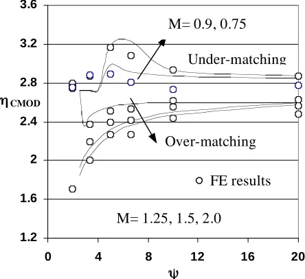
Comparison of analytical results of ηLLD and ηCMOD (from MUB approach) with those obtained from detailed FE analysis performed by the authors is shown in fig.3 and fig.4.
5.1.2 Compact tension, C(T), specimen:
For the case of deeply cracked C(T) specimen (a/W
≥ 0.3) under plane strain condition analytical solutions of limit load were presented by Khan and Ghosh (2007). Both over matched and under matched welds were analysed. It may be noted that for C(T) specimen there is no distinction between ηLLD and ηCMOD and would, therefore, be simply referred as ηp. Comparison of results of ηp obtained from MUB approach with those obtained from detailed FE analysis is shown in fig.5.
5.2 Analysis of dissimilar welded deeply cracked fracture specimens (weld centre cracks)
The integrity assessment of dissimilar/bimetallic weld joints is an important issue for the nuclear industry. These welds are typically used to connect ferritic reactor pressure vessel (RPV) nozzle with
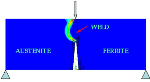
austenitic piping. Recent international surveys of such welds have revealed that there are several cracking problems due to fabrication, ageing and corrosion. The structural integrity assessment of such welds is quite complicated due to dissimilar materials and complex stress state. Integrity assessment standards, at present, do not provide any guidelines regarding the structural integrity assessment of these welds. Using the classical upper bound approach of limit analysis Khan et al (2004) has developed analytical solutions of limit load for dissimilar welded middle tension M(T), SE(B) and C(T) specimen. However, due to inherent limitation of classical upper bound approach, the maximum deviation in limit load values with respect to FE results was about 14%. Plot of equivalent plastic strains, obtained from FE analysis has revealed that in case of dissimilar welded specimen most of the plastic deformation gets confined in the weakest base material (see fig.6). Plasticity first starts at the crack tip and at the interface of weld and weakest base material. With increase in load these two plastic zones gradually increase in size and merge with each other. Thus, the weld
1.2 1.4 1.6 1.8 2 2.2 2.4
0 4 8 12 16 20
Under-matching M= 0.9, 0.75
Over-matching
M= 1.25, 1.5, 2.0
FE results
ηLLD
ψ
Fig. 3: Comparison of analytical solutions of ηLLD with FE results for SE(B) specimen.
Fig. 4: Comparison of analytical solutions of ηCMOD with FE results for SE(B) specimen.
1.2 1.6 2 2.4 2.8 3.2 3.6
0 4 8 12 16 20
Under-matching M= 0.9, 0.75
Over-matching
M= 1.25, 1.5, 2.0
FE results
ηCMOD
ψ
M= 0.9, 0.75
1.2 1.5 1.8 2.1 2.4 2.7 3
0 4 8 12 16 20
Under-matching
Over-matching
M= 1.25, 1.5, 2.0 FE results
ηp
ψ
slenderness and mismatch ratio between weld and the weakest base material governs the limit load of dissimilar welded specimens. In other words the limit load and plastic η-factor developed for similar welded fracture specimens can also be used for dissimilar welded fracture specimens. For the case of dissimilar welded C(T) specimen with a/W=0.5, comparison of limit load and plastic
η-factor obtained from MUB approach with FE results is presented in table 1 and table 2. In these table M1 and M2 describe the mismatch ratio of the two base materials with respect to weld material such as shown fig. 1(b).
Table1: Comparison of theoretical solutions of Pl Table2: Comparison of theoretical solutions of ηp with FEA with FEA
Note: In table 1 and table 2, Plr represents the ratio of limit load of dissimilar welded C(T) specimen to limit load of homogeneous C(T) specimen.
5.3 Analysis of dissimilar welded deeply cracked fracture specimens (Interfacial cracks)
In this section, analytical solutions of limit load, plastic η-factor and plastic rotation factor are presented for dissimilar welded deeply cracked fracture specimens with interfacial cracks (see fig.7). Both SE(PB) and SE(B) specimens were analysed. Comparison of analytical results with those obtained from detailed FE analyses are presented.
K = h/l
M2 M1 Plr
0.1 0.2 0.3 1.5 MUB
FEM 1.098 1.094 1.216 1.208 1.352 1.333
1 MUB
FEM 1.098 1.094 1.216 1.207 1.352 1.332 0.75 MUB
FEM 1.098 1.092 1.216 1.207 1.352 1.332 2
0.5 MUB FEM 1.098 1.092 1.216 1.207 1.352 1.329 1.25 MUB
FEM 1.059 1.049 1.132 1.127 1.22 1.21
1 MUB
FEM 1.059 1.049 1.132 1.126 1.22 1.21 0.75 MUB
FEM 1.059 1.05 1.132 1.126 1.22 1.209 1.5
0.5 MUB FEM 1.059 1.05 1.132 1.127 1.22 1.212
1 MUB
FEM 1.038 1.028 1.089 1.076 1.15 1.133 0.75 MUB
FEM 1.038 1.027 1.089 1.077 1.15 1.132 1.25
0.5 MUB FEM 1.038 1.028 1.089 1.074 1.15 1.131
K = h/l
M2 M1 ηp
0.1 0.2 0.3 1.5 MUB
FEM 2.23 2.12 2.11 1.96 1.97 1.87
1 MUB
FEM 2.23 2.13 2.11 2.01 1.97 1.86 0.75 MUB
FEM 2.23 2.12 2.11 1.97 1.97 1.9 2
0.5 MUB FEM 2.23 2.12 2.11 1.98 1.97 1.86 1.25 MUB
FEM 2.27 2.16 2.17 2.15 2.05 1.96
1 MUB
FEM 2.27 2.17 2.17 2.16 2.05 1.95 0.75 MUB
FEM 2.27 2.14 2.17 2.16 2.05 1.95 1.5
0.5 MUB FEM 2.27 2.16 2.17 2.04 2.05 1.96 1.25
1 MUB
FEM 2.29 2.24 2.21 2.12 2.1 2.08 0.75 MUB
FEM 2.29 2.20 2.21 2.11 2.1 2.07 0.5 MUB
FEM 2.29 2.21 2.21 2.13 2.1 2.08 Fig. 6: Asymmetric plastic field in a dissimilar welded
(
)
1 20.5 4
3 y l
M =
!
$*R (&#
+"
')+x R+ x %+,
-. /
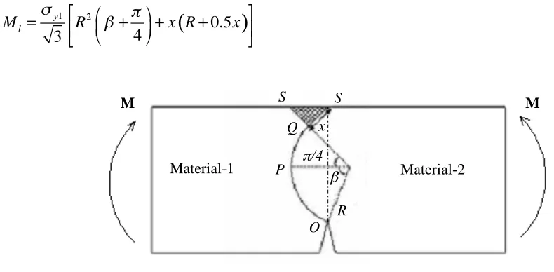
5.3.1 Single edge cracked bend specimen subjected to pure bending load, SE(PB): For the case of dissimilar welded SE(PB) specimen with interfacial crack, the assumed plastic field is shown in fig.7. A circular arc, OPQ, emanates from the crack tip and it merges tangentially into the constant stress (compressive) region, SQS. It may be noted that this proposed plastic field is exactly the same that was used to analyse homogeneous SE(B) specimen (Khan and Ghosh, 2007). The assumed plastic field and hence the results presented in this section are valid for deeply cracked SE(PB) specimen with a/W>0.3. It is recognised that though the shape of plastic field and hence the limit load, in general vary, with the mismatch ratio (between material-1 and material-2), however, in case of interfacial crack it was observed that this dependence is very weak (Kim, 2002). Therefore, variation of limit load as a function of mismatch ratio has not been examined in detail. Instead for the limiting case of extreme mismatch theoretical solution is proposed.
From MUB approach the limit moment for this case can be expressed as
(8)
Comparison of analytical results obtained from MUB approach (Eq.8) with those obtained from detailed FE analysis performed by the authors is presented in table 3. In this table, M=∞ simply means that the stronger material was modelled as elastic.
5.3.2 Single edge cracked bend specimen subjected to three-point bending load, SE(B): For the case of dissimilar welded SE(B) specimen with interfacial crack, FE analysis has revealed that there is no significant influence of material mismatch on limit load and plastic η-factor. The weaker material essentially governs these parameters. Thus all the results of homogeneous SE(B) specimen can be used for this case without any significant error.
6.0 CONCLUSION
• MUB approach can give reasonably good estimate of the limit load for similar welded fracture specimens with weld centre cracks. For plastic η-factor, MUB approach gives correct trend, however, the analytical solutions were not in such good agreement with FE results. The maximum difference was about 12%. This does not mean that either the proposed limit load solutions or their partial derivative with respect to crack size are not accurate. This difference is due to the inherent assumption of load separation principle that is used to evaluate plastic η-factor from limit load solution.
• The weld slenderness ratio and the mismatch ratio between weld and the weakest base material govern the limit load of dissimilar welded specimens with weld centre crack. Thus, the limit load and plastic η -factor developed for similar welded fracture specimens can also be used for dissimilar welded fracture specimens.
Fig. 7: Assumed plastic field for a dissimilar welded SE(PB) specimen with interfacial crack. M
M
R P
Q
Material-2 β
π/4 S S
Material-1
x
• For dissimilar welded fracture specimen with interfacial crack mismatch ratio has a mild influence on limit load. For the case of extreme mismatch (M=∞)
(1) Increase in limit moment for SE(PB) specimen is about 5%.
(2) Increase in plastic rotation factor for SE(PB) specimen is about 20%. (3) Reduction in ηCMOD is about 12%
Table3: Comparison of analytical solutions with FE results.
Note: In table 3, represents the ratio of limit moment of dissimilar welded SE(PB) specimen with interfacial crack to limit moment of homogeneous SE(PB) specimen.
7.0 REFERENCES
Hao, S., Cornec, A., Schwalbe, K.H., 1997. Plastic stress-strain fields and limit loads of a plane strain cracked tensile panel with a mismatched welded joint. International Journal of Solids and Structures, 34 (3), 297-326.
Hao, S., Schwalbe, K.H., Cornec, A., 2000. The effect of yield strength mis-match on the fracture analysis of welded joints: slip-line field solutions for pure bending. International Journal of Solids and Structures, 37, 5385-5411.
Hill, R., 1950. The Mathematical Theory of Plasticity. Clarendon Press, Oxford.
Joch, J., Ainsworth, R.A., and Hyde, T.H., 1993. Limit load and J-estimates for idealised problems of deeply cracked welded joints in plane-strain bending and tension. Fatigue Fracture of Engineering Materials and Structures, 16 (10), 1061-1079.
Johnson, W., and Mellor P.B., 1973. Engineering Plasticity. Von Nostrand Reinhold Company, New York. Kachanov, L.M., 1971. Foundation of the theory of Plasticity. Amsterdam, North-Holland.
Khan I.A., Bhasin V., Chattopadhya J., Ghosh A.K., 2008. On the equivalence of slip-line fields and work principles for rigid-plastic body in plane-strain. International Journal of Solids and Structures, 45, (25-26) 6416-6435.
1.09 1.124
0.44 0.447
0.385 0.375
∞
1.09
-0.383
-5
1.104
-0.38
-2
-0.375
-1.25
1.12 1.144
0.37 0.37
0.364 0.364
1
0.8
1.53 1.63
0.45 0.447
0.383 0.375
∞
1.53
-0.381
-5
1.55
-0.378
-2
-0.373
-1.25
1.729 1.79
0.37 0.37
0.364 0.364
1
0.3
FEA MUB
FEA MUB
FEA MUB
CMOD rp
Khan I.A., Bhasin V., Vaze K.K., Ghosh A.K., Kushwaha H.S., 2004. An estimation procedure to evaluate limit loads of bimetallic specimens. International Journal of Pressure Vessels and Piping, 81, 451-462. Khan I.A., Ghosh A.K., 2007. A modified upper bound approach to limit analysis for plane strain deeply cracked specimens. International Journal of Solids and Structures, 44, (10), 3114-3135.
Kim, Y, J., 2002. Experimental J estimation equations for single-edge-cracked bars in four-point bend: homogeneous and bi-material specimens. Engineering Fracture Mechanics,69, 793-811.
Kim, Y.J., Kim, J.S., Schwalbe, K.H., Kim, Y.J., 2003. Numerical investigations on J-integral testing of heterogeneous fracture toughness testing specimens: Part I-weld metal cracks. Fatigue Fract Engng Mater Struct., 26, 683-694.
Kim, Y, J., Schwalbe, K.H., 2001. Mismatch effect on plastic yield loads in idealised weldments. I. Weld centre cracks, Engineering Fracture Mechanics,68, 163-182.
Kim, Y, J., Schwalbe, K.H., 2001Compendium of yield load solutions for strength mis-matched DE(T),SE(B) and C(T) specimens, Engineering Fracture Mechanics,68, 1137-1151.
Kirk, M.T., Dodds, R.H., 1993. J and CTOD estimation equations for shallow cracks in single edge notch bend specimens. Journal of Testing and evaluation, 21, 228-238.
Schwalbe K. H., Cornec A., Lidbury D., 2004. Fracture mechanics analysis of the BIMET welded pipe tests. International Journal of Pressure Vessels and Piping, 81, 251-277.
Sharobeam, M.H., Landes, J.D., 1993. The load separation criterion and ηp development in precracked specimen test records. International Journal of Fracture, 59, 213-226.