University of Windsor University of Windsor
Scholarship at UWindsor
Scholarship at UWindsor
Electronic Theses and Dissertations Theses, Dissertations, and Major Papers
1-1-2005
Real-time systems for moving objects detection and tracking
Real-time systems for moving objects detection and tracking
using pixel difference method.
using pixel difference method.
Bo Shen
University of Windsor
Follow this and additional works at: https://scholar.uwindsor.ca/etd
Recommended Citation Recommended Citation
Shen, Bo, "Real-time systems for moving objects detection and tracking using pixel difference method." (2005). Electronic Theses and Dissertations. 6956.
https://scholar.uwindsor.ca/etd/6956
Real-time Systems for Moving
Objects Detection and Tracking
Using Pixel Difference Method
by
Bo Shen
A Thesis
Submitted to the Faculty o f Graduate Studies and Research through the School o f Computer Science
in Partial Fulfillment o f the Requirements for the Degree o f Master o f Science at the
University o f Windsor
Windsor, Ontario, Canada 2005
Library and Archives Canada
Bibliotheque et Archives Canada
Published Heritage Branch
3 9 5 W ellington S treet Ottawa ON K1A 0N 4 C anad a
Y our file Votre re fe re n c e ISBN: 9 7 8 -0 -4 9 4 -3 4 9 6 3 -2 O ur file N otre re fe re n c e ISBN: 9 7 8 -0 -4 9 4 -3 4 9 6 3 -2
Direction du
Patrimoine de I'edition
3 9 5 , rue W ellington Ottawa ON K1A 0N 4 C an ad a
NOTICE:
The author has granted a non exclusive license allowing Library and Archives Canada to reproduce, publish, archive, preserve, conserve, communicate to the public by
telecommunication or on the Internet, loan, distribute and sell theses
worldwide, for commercial or non commercial purposes, in microform, paper, electronic and/or any other formats.
AVIS:
L'auteur a accorde une licence non exclusive permettant a la Bibliotheque et Archives Canada de reproduire, publier, archiver,
sauvegarder, conserver, transmettre au public par telecommunication ou par I'lnternet, preter, distribuer et vendre des theses partout dans le monde, a des fins commerciales ou autres, sur support microforme, papier, electronique et/ou autres formats.
The author retains copyright ownership and moral rights in this thesis. Neither the thesis nor substantial extracts from it may be printed or otherwise reproduced without the author's permission.
L'auteur conserve la propriete du droit d'auteur et des droits moraux qui protege cette these. Ni la these ni des extraits substantiels de celle-ci ne doivent etre imprimes ou autrement reproduits sans son autorisation.
In compliance with the Canadian Privacy Act some supporting forms may have been removed from this thesis.
While these forms may be included in the document page count,
their removal does not represent any loss of content from the thesis.
Conformement a la loi canadienne sur la protection de la vie privee, quelques formulaires secondaires ont ete enleves de cette these.
Abstract
Tracking o f multiple moving objects from ‘real world’ in an image sequence is a very
important task in Computer Vision. In particular, there are many problems in which
objects undergoing motion must be detected and tracked. In this thesis, two tracking
systems are introduced: Fish-Tracker System and Human-Counter System. In these two
systems, the objects are tracked through a sequence o f frames and the motion detection
algorithm is used based on frame pixel difference. Fish-Tracker system is developed for
department o f Biological Sciences to determine spent time, path and velocity o f moving
fish. The direction and velocity o f each object are calculated between each pair o f frames
and are used to predict the position o f the object in the next frame. The calibration,
reconstruction procedure and the problems due to the presence o f noise and shadows in
the images are also addressed. Human-Counter system is kind o f surveillance system
that is important for the office security or the marketing research. In this system, some
basic image morphological operations such as opening and closing are employed to
reduce noise. The adopted strategies such as a connected components algorithm and
Table of Contents
Abstract... iii
L is t o f F ig u r e s ... vii
1. Introduction
1
1.1 Definition... 11.2 Features used in object detection... 2
1.3 The Four elements in tracking system... 4
1.4 Thesis overview... 5
2. Background for Vision-Based Object Detection and Tracking
7
2.1 Camera calibration... 72.2 Three-dimensional reconstruction... 11
2.3 Foreground segmentation methods used in object detection... 12
2.4 Image morphological operations... 16
2.4.1 Erosion and dilation... 16
2.4.2 Opening and closing... 18
2.5 Boundary extraction... 20
2.6 Conclusion... 21
3. Tracking System Approach
22
3.1 Pixel difference m ethod... 233.1.1 F rame difference... 24
3.1.2 Background subtraction... 24
3.2 Removing noise and foreground blob computing... 25
3.3 Object type classification... 27
3.4 Object tracking... 29
4. A real-time tracking system
Fish-Tracker
32
4.1 Motivation o f our Fish-Tracker system... 32
4.2 The approach o f Fish-Tracker system... 33
4.3 Detecting moving fish... 33
4.4 Removing shadow... 34
4.5 Extracting feature point... 36
4.6 Camera calibration... 36
4.7 Trajectory ofm ovingobjects... 38
4.7.1 Computing the path o f single fish... 39
4.7.2 Calculating the speed o f single fish... 40
4.7.3 Computing the paths o f two fish... 41
4.7.4 Calculating the speed o f two fish... 42
4.8 Time spent analyses... 43
4.9 Conclusion... 44
5. Another real-time tracking system
Human-Counter
45
5.1 Human identification and activity recognition... 455.1.1 Human presence detection... 45
5.1.2 Human motion classification... 46
5.1.3 Gait recognition methods... 47
5.2 Human extraction... 48
5.3 Human body models... 49
5.4 Real-time human tracking systems... 51
5.5 The approach o f our Human-Counter system... 54
5.5.1 Background subtraction... 55
5.5.2 Noise reduction (opening-closing)... 56
5.5.3 Object group connection... 57
5.5.4 Object group analyses... 58
5.6 Conclusion... 59
Bibliography... 61
List of Figures
Figure 1.1 Object detection based on shape in W4 system... 2
F igure 2.1 3 D-2D correspondence proj ection... 8
Figure 2.2 2D-2D correspondence projection... 10
Figure 2.3 Snakes for clock face... 14
Figure 2.4 Effect o f Erosion using a 3 ><3 square structuring element... 17
Figure 2.5 Effect o f Dilation using a 3 ><3 square structuring element... 18
Figure 2.6 Erosion, Dilation and Opening... 18
Figure 2.7 Effect o f opening using a 3x3 square structuring element... 19
Figure 2.8 Effect o f Closing using a 3x3 square structuring element... 20
Figure 2.9 Effect o f boundary on image A using structure B ... 20
Figure 3.1 Tracking system approach... 22
Figure 3.2 Meandering algorithm... 26
Figure 3.3 Neighborhood structure-Region growing algorithm... 27
Figure 3.4 Neural network approach to object classification... 28
Figure 4.1 Detecting Fish - pixel difference... 34
Figure 4.2 Fish moving path - image subtraction... 34
Figure 4.3 Detect Extra Shadows... 35
Figure 4.4 Removing Shadow... 35
Figure 4.5 Fish path after Removing Shadow... 35
Figure 4.6 Getting Feature Point pixel stands for fish... 36
Figure 4.7 Fish path after getting feature point... 36
Figure 4.8 2D —3D correspondence... 37
Figure 4.9 2D —2D correspondence... 37
Figure 4.10 Calibration pattern... 37
F igure 4.11 Calibration... 38
Figure 4.12 Fish path... 39
Figure 4.13 Fish path diagram... 40
Figure 4.14 Fish speed diagram... 41
Figure 4.15 Two fish paths... 41
Figure 4.16 Two fish path diagram... 42
Figure 4.17 Two fish speed diagram... 43
Figure 4.18 Defined Flume Regions... 43
Figure 5.1 Static feature extraction and dynamic feature extraction... 49
Figure5.2 Cardboard human m odel... 49
Figure 5.3 3-D stick m odel... 50
Figure 5.4 Ellipses Human model... 50
Figure 5.5 Truncated Cones human M odel... 50
Figure 5.7 Distinguishing single person and people group in W 4... 53
Figure 5.8 Tracking single person... 54
Figure 5.9 Counting number o f people... 54
Figure 5.10 Snake-curve representing the number of people... 54
Figure 5.11 Example o f background subtraction... 56
Figure 5.12 Example o f Noise Reduction... 57
Figure 5.13 Example o f Group Connection... 58
Chapterl
Introduction
Tracking of multiple moving objects from ‘real world’ in an image sequence is a very
important task in Computer Vision. In particular, there are many situations in which
objects undergoing motion need to be detected and tracked. For instance, security and
surveillance - to identify anomalous behavior in a parking lot or near an ATM;
Medical therapy - to improve the quality of life for disabled people; Retail space
instrumentation - to analyze shopping behavior of customers; Traffic management - to
detect pedestrians and accidents; Interactive games - to provide interaction with
intelligent systems and so on.
1.1 Definition
Object detection is the process of locating and segmenting a foreground object from
background in image sequences for recognizing object type. Object tracking is used to
match the target region during successive image sequences for estimating an object’s
spatial and temporal changes including its position, shape, motion and etc. These two
processes are related because tracking usually starts with detecting objects, while
detecting an object repeatedly in subsequent image sequence is often necessary for
object tracking.
Detecting moving objects based on motion has very important significance in object
detection and tracking. Compared with object detection without motion, motion
detection complicates the object detection problem by adding object’s temporal
change requirements. A large variety o f motion detection algorithms have been
proposed. Pixel Difference technique is one important motion detection technique
used in lots of real-time tracking systems. Pixel Difference technique relies on the
detection o f temporal changes at pixel level. The difference map is usually binarized
using a predefined threshold value to obtain the motion/no-motion classification.
Pixel Difference technique is a particularly efficient and sensitive method for
1.2 Features used in object detection
Foreground objects can be detected from the background in image sequences
according to different features. One or more features are extracted and the objects of
interest are modeled in terms of these features. Then object detection and recognition
can be transformed into a feature-matching problem. The features used in object
detection are as follows:
• Object detection based on shape
Object detection based on shape is useful when it is difficult to extract reliable
features for tracking. It is very complicated because not only we need to detect and
determine the border of an object by edge detection and boundary-following
algorithms but also need to remove noise by a preprocessing algorithm. A human
body can be decomposed into approximate* shapes such as an ellipsoid for the head
and truncated cones for the limbs. The detection and shape characterization o f the
objects become more difficult for complex scenes where there are many objects with
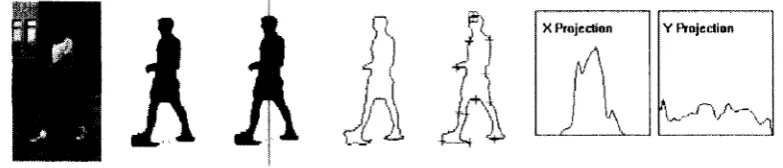
occlusions and shading. For example, W4 system introduced in [HHD98] is a real time system for tracking people and their body parts in monochromatic imagery. W4
employs a combination of shape analysis and robust techniques to detect people, and
to locate and track their body parts (Figure 1.1). This Figure shows that each detected
foreground object can be represented by generating global shape and appearance
features such as centroid (median coordinate of foreground region) and major axis. In
addition, the shape of 2D silhouettes is represented by horizontal and vertical
projection histogram.
• Object detection based on color
Object detection based on color is relatively simple because color is constant and easy
to be acquired. However, color is not always appropriate as the sole means of Y P rojection X Projection
detecting and tracking objects. For example, it is difficult to distinguish between a
field o f orange flowers and a tiger, because it lacks information about how the color is
distributed spatially. It is important to group color in localized regions and to fuse
color with textural properties. Heisele in [HKR97] develops an algorithm to detect and track vehicles or pedestrians in real-time using color cluster based technique.
Each image is divided into given number of clusters by grouping pixels of similar
color and position. Pfinder (“Person finder”) [WAD97J is a real-time system for tracking people. The system uses a multi-class statistical model of color and shape to
obtain a 2D representation of the head and hands. Each pixel in the background is
associated with mean color value and a covariance matrix that describes the color
distribution of each pixel. Meanwhile, Pfinder can detect a differently colored region
as change in scene. Each blob that corresponds to the person’s hands, head, feet, shirt
and pants locations respectively has a spatial (x, y) and color (Y, U, V) component, and also have a detailed representation of its shape and appearance.
• Object detection based on template
Object detection based on template is a process of matching features between the
template and the image sequence under analysis. There are two types of object
template matching, fixed and deformable template matching. Fixed templates are
useful when object shapes do not change with respect to the viewing angle of the
camera. Deformable template matching approaches are more suitable for cases where
objects vary due to either the deformation of the object or different object pose
relative to the camera. Jain in [JZL96] propose a general object localization and retrieval scheme based on object shape using deformable templates. Prior knowledge
of an object shape is described by a prototype template that consists o f the
representative contour/edges, and a set of probabilistic deformation transformations
on the template. A scheme, which is based on this prior knowledge and the edge
information in the input image, is employed to find a match between the deformed
template and objects in the image. Their method has been applied to retrieve objects
with a variety of shapes from images with complex background. The proposed
scheme is invariant to location, rotation, and moderate scale changes of the template.
• Object detection based on motion
Object detection based on motion or detecting moving objects has very important
motion, motion detection complicates the object detection problem by adding object’s
temporal change requirements. A large variety of motion detection algorithms have
been proposed. They can be classified into the following groups.
1). Thresholding technique according to the frame difference
These approaches such as [DN90] rely on the detection of temporal changes either at pixel or block level. The difference map is usually binarized using a predefined
threshold value to obtain the motion/no-motion classification.
2). Global frameworks —dense motion estimates
Many algorithms estimate the optical flow (velocity field in the image plane) that is
the projection of the 3D-motion in the image plane. In subsequent motion
segmentation, each image is divided into segments corresponding to objects with
different motion properties. There are two important requirements for this approach:
dense motion estimates must be calculated and motion discontinuities must be
preserved. The main problem of this approach is that the optical flow cannot be
reliably estimated in image parts with approximately uniform intensity and it is
usually very time consuming.
1.2 The four elements in Tracking Systems
There are numerous real word applications o f tracking system using different
algorithms and procedures. However, as stated in [WJ, all tracking systems usually have four elements: target representation, observation representation, hypotheses
measurement and hypotheses generating.
The target representation — such as size, color, shape, and motion — characterizes the target in a state space. For example, shapes in [HHD98] and color distributions in
[HKR97] are often employed as target representations. Some methods employ both shape and color like in [WAD97J. Sometimes motion could also be taken into account in target representations, since different objects can be segmented by the differences
o f their motions.
The observation representation defines the image features observed in the images. For instance, if the target is represented by its color appearance like in [HKR97] and
observation o f the target. If the target is characterized by its contour shape like in
[HHD98], we should observe edges of the contour in the image.
The hypotheses measurement matches target state hypotheses with their image observations. In general, the question we often ask is that, given a certain image
observation, which hypothesis will be most likely to produce such an image
observation. For instance, in [JZL96], the template-matching tracking method takes SSD as the measurement. SSD is short for sum-of-squared-difference. The fewer the
SSD measurement is, the higher the probability of the hypothesis will be.
The hypotheses generating produces new state hypotheses based on old estimation of target’s representation and old observation. Two commonly used hypotheses
generating algorithms in tracking are Kalman filtering in [K60], [LJH] and CONDENSATION algorithm in [IB98]. Kalman filtering is a prediction-correction procedure under Gaussian assumptions, which the density could be characterized by
its mean and covariance. By encapsulating the motion of the object into internal
states, Kalman filtering aims at finding appropriate states that gives best-fit
observations. Dynamic equation and measurement equation will be used in Kalman
filter for representing the change in internal states and conversion from internal state
to observation respectively. Although Kalman filter’ approach is fast, it suffers from a
few and yet serious problems. For instance, too much prior knowledge is required,
dynamic model should be provided, the uni-modal Gaussian distribution is assumed
and clutter background is not allowed. To overcome these problems,
CONDENSATION (conditional density propagation) algorithm was developed. It
aims at finding most probable area containing the feature or object based on sampling.
By allowing more than one hypothesis, CONDENSATION algorithm can recover
from false tracking o f ambiguous feature or object. The larger the size o f the samples,
the more accurate the tracking result will be. However, larger sample size also implies
higher computational time. As such, there is a tradeoff between time complexity and
accuracy.
1.3 Thesis Overview
This thesis is organized as follows. Chapter 2 provides the theoretical background of
an overview about basic steps o f general object tracking systems. Chapter 4 describes
our interactive Fish-Tracker System used for biology department, including the
implementation details and experiment results. Chapter 5 discusses different aspects
of human identification and activity recognition, presents our Human-Counter System
that is used for counting the number of people in the room. Chapter 6 is the
Chapter2
Background for Vision-based object detection
and tracking
Object detection and tracking are very important task in computer vision and many
related techniques have been developed. The major goal o f object tracking is to
compute properties o f objects in 3-D world from digital images. A space point in 3-D
world and its 2D projection point are linked by the projection matrix that can be
obtained from camera calibration process. After Camera calibration and 3D
reconstruction, the properties o f objects in 3-D world are straightforward. Foreground
segmentation is a process used in object detection to partition a digital image into
disjoint regions of interest based on some similarly criteria, such as intensity, region
or boundary. Noise can have a dramatic effect on the magnitude o f difference images
and recognize wrong object, despite the fact that no interest object have been in that
region. Some basic morphological operations such as: erosion, dilation, opening and
closing, are particularly useful for the analysis of binary images and common usages
including noise removal, edge detection. To establish the necessary background for
object detection and tracking, some related techniques in computer vision mentioned
above are discussed here.
2.1
Camera Calibration
It is straightforward to get some information about 2D point from image sequences,
but our goal in object tracking is to compute properties of objects in 3-D world from
these digital images. To that end, we need to know the projection matrix and the
camera parameters. Camera calibration is a fundamental problem in computer vision
and is a necessary step to extract metric information from 2D images. It is a process
of determining the intrinsic and extrinsic parameters o f the camera, or the process of
estimating the projection matrix. A perspective projection matrix is the link between
the 3D space points and the 2D pixel points.
Camera calibration techniques are roughly classified into two categories: pattern-
based calibration and self-calibration [ZOO]. Pattern-based calibration uses a special calibration object, called calibration pattern. The calibration pattern’s geometry in 3D
pattern, the correspondences between the 3D feature points and their 2D projections
can be built. This set of data contains projection information and can be used to derive
the intrinsic and extrinsic parameters. Pattern-based camera calibration can be done
very efficiently. A well-known example is Tsai’s calibration algorithm [T87], A recently improvement by Zhang’s calibration algorithm in [ZOO] makes it possible to use a planar calibration pattern, which considerably improves the flexibility. Self
calibration does not use the calibration pattern. The calibration process is to move the
camera rigidly and take images with fixed intrinsic parameters; the correspondences
between three images are sufficient to recover both intrinsic and extrinsic parameters.
This approach is quite flexible, but it is not mature yet. Because there are many
parameters to estimate, we cannot always obtain reliable results. A 3D point P must undergo the following steps to be projected onto the image plane:
1) Euclidian transformation from world reference frame to camera reference frame. It can be expressed as a 3*4 matrix D, in which 6 extrinsic parameters are held, namely a rotation and a translation.
2) A 3D-2D perspective projection, projecting point P onto the image plane within the camera reference frame. It can be expressed as a 3* 4 matrix I.
3) A 2D-2D transformation from camera reference frame to image coordinates. It can be expressed as a 3*3 matrix A, in which 4 intrinsic parameters are held.
Therefore, the projection matrix M ean be expressed as a 3 * 4 matrix M:
M = AID
The projection o f a space point P = (X, Y, Z, 1) onto the image point p = (u, v, 1) is 3D-2D projection. (Figure2.1)
p rin c ip a l a x is im a g e p la n e
The projection can be expressed as:
f
V
= X
,
1
>
I
m u ^ 1 2 ^ 1 3 m u
m 21 m 2 2 m 23 m24 77131 77732 777-33 77734
f X \
Y
Z
U . J
It is a 3D-2D response projection (figurel), where A is the scale factor. Equation
provides two basic projection equations describing the relationship between points
defined in space {X, Y, Z) and their corresponding pixels (u, v):
V
m
11
X
+ 771 ] 2 y + 777.13 Z + fflii
77731
X
+
m & Y
+ 77733 Z + 771st
m a t A ' + ilia s Y + 1W2 3Z + m 2
1
77731A" +
77132Y + mm Z
+
m u
where mij , i = 1 ...3 , j = 1... 4 are the entries of projection matrix. At least 6 points are needed to solve 12 entries o f projection matrix M. A singular value decomposition
(SVD) is a good method to solve the equation:
/ - X l - n -Z i -1 0 0 0 0 uiXi u ifi tuZi U1 ^ 0 0 0 0 -X i -Yi -Z i - I 01 Xi « lfl «vZi 111 -X a -Yi - z 2 -1 0 0 0 0 112 X 2 uoV’i «2Z2 us o 0 0 0 -X s -Yi -Z 2 - I 1'2 A' 2 B2f2 V2Z2 n
- x » -Yn -z» -1 0 0 0 Q UflXn tinYn un
\ o 0 0 0 -Z „ -Yn - 7 -1 llnfn B»Zn *n J raj-}
J«14 injji
ra22
t»23
”>31
ra33
\mM = 0
Sometimes, we need to track moving objects along a plane. In such case, points from
calibration pattern are mapped to the image points on the image plane (2D-2D
u
►---V
' 'lin a g e p la u e
I I
calibration pattern plane
z
Figure2.2. 2D-2D correspondence projection
The projection o f a space point P = (X, Y, 1) onto the image point p = (x, y, 1) can be expressed as:
' h-a h l2 hV j'
V
= A
/t21 h%2 ft-23 ■Ui
„ h$l fo$2 &33 , \or,
p = X H P
At least four points are needed in order to calculate homography matrix H. The
calculation o f the matrix H is usually very sensitive to the noise in the image. It
usually requires the knowledge o f more than 4 points on the motion plane and their
projections on the image.
In [BM98], the calculation o f H is reduced to the calculation o f only 3 parameters. This minimal parametrization of the homography matrix allows a robust calculation
even when the number of point correspondences is small. This is done by a change in
the coordinate systems in both the image and the motion plane. Indeed, consider the
image points po, pi, P2 and p3, and their corresponding points in the scene po\ p i’, P2’ and P3’. The points p i’, p2’ and P3’ must belong to the motion plane, while the point pO’must not be on this plane. These 4 points must form a projective basis, i.e., no
P i
P2
Pa
PG
(
0
,
0
, i f
(1,0,0)T
(0,1,0)T
(
1
,
1
,
1
)
7-P i
P2
Ps
Po
(0 ,0 ,1)T
(1,0, o f
(0 ,1 , 0)T
( 1 , 1 , 1)T
Under such choice of coordinate systems, the homography matrix H, such that
p! — H p j(i = 1,2,3) is diagonal, that is H = diag{at, 0 , ^ ) . Because of the equality up to scale factor H now depends on only 2 parameters. The original matrix
is recovered by applying the inverse transformations on the left and right hand sides
of the diagonal matrix.
2.2 Three-dimensional Reconstruction
After having point correspondences identified, the 3D reconstruction from calibrated
images is straightforward. A space point and its 2D projection point is linked by the
projection matrix which has been already attained from calibration stage:
( X '
Y
Z
1 j
If we know the projection matrice and the projections of a space point in both the left
and the right image, we can easily recover that space point’s 3D coordinates (X; Y; Z)
by solving the following 4 equations:
f
u m-12 m % 777-14
V
= A
m i m2
m -iz 77124U i
m-32 771-33 77134j
u =_ / / i n A ' + r n i
2
Y + m 13Z + m i4 m 31 X + m sa y 4- r n ^ z + m 43 ■m2i X + m ^ Y + m 23Z + m 24 •m31A'm
u
=it-+ m 32l '
+ m 421'
+ m 33Z + m 43
4- r n 'isZ + m '14
i/ =
m 31 X
m ^ X
+ m 32y
+ m'22y
+
n Y i Z+
m 4 3 -j- m 23Z + m 2432 33" 43
We have 4 equations and 3 unknowns. The above equation can be rewritten as
/
TOu -
ni^i'U irii
2
- rnmu
ml3 - m33u
m21 -
mmv
m22 - m
32v
m23 - m
33v
\
m'n — mgj u1
\ " 4 i
-mi
2“
m'nu>
m 13 “ m 3 3 u ' ™ 23 ~ " 4 * ' ' //x\
y
v*/
/
m 34tt — ?n y\
rri^v — m-jA
m'u u? - m'u
X’n 'u 1-- ~ ” '24 /
Equation can easily be solved by SVD method. In summary, the coordinates of a
space points can be recovered by knowing its projections on at least two calibrated
images.
In case o f tracking a moving object along a plane, points from a calibration pattern are
mapped to the image points on the image plane (2D-2D projection). A space point P = (X, Y, 1) and its 2D projection point p = (x, y, 1) is linked by the homography matrix:
h u Hu f h z'
f
X \ y = A ^21 ft-22 h -Zi • Y U J ^ i h$2 jI
1 / or,p = \ H P
If we know the homography matrix and the projections of a space point in the image
plane (x, y) we can easily recover that space point’s coordinates (X; Y).
2.3 Foreground segmentation methods used in object detection
Object detection first need to locate and segment a foreground object from
background in a sequence o f images. Image segmentation is the grouping o f image
pixels based on some similarly criteria, such as intensity, region or boundary. The
goal o f image segmentation is to partition a digital image into disjoint regions of
interest. Depending on the technique, the criteria may be different. Some methods are
based on pixel statistics such as intensity. Other methods try to enclose regions within
a boundary. Healy in [HC85] classified segmentation techniques into global, region homogeneity and boundary finding. The global techniques are those that assign a
pixel’s membership based on information from the entire image. Region homogeneity
groups pixels based on some similarity of criteria around pixels. Finally, boundary-
same classification, but employs more specific techniques: binarization and clustering
instead o f global techniques.
• Binarization-based approach
Binarization-based approach, same as threshold technique, is based on finding optimal
threshholding to separate the foreground objects of an image from the background.
Threshold techniques, which make decisions based on local pixel information, are
effective when the intensity levels of the objects fall squarely outside the range of
levels in the background. Frame difference and Background segmentation method can
be categorized as Binarization-based approach.
• Clustering-based approach
Clustering-based approach is an image restoration method that classifies pixels into
clusters based on some attributes. For example, in [HKR97], the algorithm estimates image motion by tracking clusters determined in the color/position feature space.
Each image is divided into a given number of clusters by grouping pixels o f similar
color and position. Adjacent clusters with similar motion are combined to build
interest objects.
• Boundary-based approach
Boundary-based approach depends on the information provided by the object
boundaries. The boundary-based approach usually uses active contour models. The
active contour model is defined as an energy-minimizing spine (also called “snake”)-
the snake's energy depends on its shape and location within the image. Snake is a
deformable active contour used for boundary tracking which was originally
introduced by [KWT98J. It is basically a complex edge finding algorithm, which traces edges o f objects and finds humans by their unique shape (a spherical head on a
body) in human tracking. The main idea is to start with some initial boundary shape
represented in the form of spline curves, and iteratively modifies it by applying
various shrink/expansion operations according to some energy functions. Local
minima o f this energy then correspond to desired image properties. Snakes are the
optimization way of finding structures. For example, suppose we are interested in the
outlines o f the clock faces. We might start by looking to see whether image edges will
help. Maybe there isa simple contour round the clock face, but sometimes the contour
show up in the edge map. Clearly, using an edge detector alone, however good it is,
will not separate the clock faces from other structure in the image. We also can find
the clock faces by using extremely exact 2-D models o f their images - ellipses with known dimensions and orientations. But it is unreasonable to expect that such detailed
information will normally be known in advance. We might want to weaken the
conditions further, and look for a shape in the image that is smooth and forms a closed contour, but which is not necessarily elliptical. Active contour models, or snakes, allow us to set up such general conditions, and find image structures that satisfy the
conditions. This can be illustrated in Figure2.3, suppose we know that there is a clock
face in the rectangular region o f the image. We can set up a snake to start on this
rectangle. Then, we can tell the snake to shrink, to try to form a smooth contour, and
to avoid going onto brighter parts of the image. The final position of the snake has
converged on the contour o f the outside o f the clock face, distorted a little by the
bright flint at 1 o'clock.
Figure 2.3. Snakes for clock face
The snake structure has a very simple form. They consist of a set of control points,
effectively connected by straight lines. Each control point has a position, given by (X,
Y) coordinates in the image, and a snake is entirely specified by the number and
coordinates o f its control points. Moving the control points makes adjustments to the
snakes. Snakes use an energy minimizing spline that is deformed by constraint forces.
M. Kass, A. Witkin, and D. Terzopoulos in [KWT98] describe three forces: • Internal forces modeling the bending o f the contour
• Image forces representing information such as edges
• Constraint forces to provide any additional external forces
In segmentation and boundary tracking problems, these forces relate to the gradient of
image intensity and the positions o f image features. One advantage o f the force-driven
images. The snakes are usually parameterized and the solution space is constrained to
have a predefined shape. So these methods require an accurate initialization step
associated with the solution of a partial differential equation o f motion. Active
contour had been used in pattern location and tracking for a long time. [CB92], [CC96], [KWT88J, [WWJ, [WAD97J and [MT93] all use active contour. It is good at attaching to an object with strong edges and irregular shapes. In [WWJ, the initial position of the active contour is usually the bounding box of the searching window. It
searches for strong edges along the direction towards to centroid of potential region. It
stops at the pixel with strong edge characteristic and close to the skin-color region. By
searching along the line joining the initial position and the centroid, the pixel with
strong edge information is picked as potential contour. In [WAD97J, Pfinder uses a 2D contour shape analysis that attempts to identify the head, hands, and feet location.
[CB92] proposes a B-spline representation of active contours, and [MT93] proposes a deformable quadric model for modeling of shape and motion of 3D non-rigid objects.
They consider the case o f quadric ellipsoids with tapering and bending deformations.
Geodesic active contour models are not parameterized and can be used to track objects that undergo non-rigid motion. In [CC96], a three steps approach is proposed which starts by detecting the contours of the objects to be tracked. An estimation of
the velocity vector field along the detected contours is then performed. At this step,
very unstable measurements can be obtained. Following this, a partial differential
equation is designed to move the contours to the boundary o f the moving objects.
These contours are then used as initial estimates o f the contours in the next image and
the process iterates.
• Region-based approach
Region-based approach groups pixels into regions based on some criteria of
homogeneity among neighboring pixels and relies on information provided by the
entire region such as texture and motion-based properties. A region-based method
usually proceeds as follows: the image is partitioned into connected regions by
grouping neighboring pixels of similar intensity levels. Adjacent regions are then
merged under some criteria involving perhaps homogeneity or sharpness of region
boundaries. With Region-based approach, the estimation of the target's velocity is
based on the correspondence between the associated target regions at different time
correspondence is required within the whole region. But region-based approach
increases robustness due to the fact that the whole region provides information.
Computing Optical flow like in [JB93] is one of the widely used methods in this
category. With this method, the apparent velocity and direction of every pixel in the
frame have to be computed. Although it is a little bit time consuming, this method is
very useful in detecting and tracking objects in video with moving background or shot
by a moving camera.
2.4 Image morphological operations
Sometimes when tracking system locates and detects foreground regions from
background in image sequences, we cannot obtain clear foreground regions. Some
small regions like noise spikes and ragged edges due to illumination changes should
be eliminated first. We usually apply some basic image morphological operations to
binary image to remove such noise. The morphological operations are particularly
useful for the analysis o f binary images and common usages including edge detection,
noise removal, image enhancement and image segmentation.
2.4.1 Erosion and Dilation
The two most basic operations in mathematical morphology are erosion and dilation.
Both o f these operators take two pieces o f data as input: an image to be eroded or
dilated, and a structuring element. Erosion, Dilation and their combined usage are
ways of adding or removing pixels from the boundaries of features in order to smooth
them, to join separated portions of features or separate touching features, and to
remove isolated pixel noise from the image. Dilation turns pixels "on" according to
rules based on the number or arrangement o f neighboring pixels, while Erosion turns
pixels "off' according to similar rules. Dilation increases the size o f objects, while
Erosion reduces the size o f objects. Morphological operations are usually performed
on binary images where the pixel values are either 0 or 1. For simplicity, we will refer
to pixels as 0 or 1, and will display a value o f zero as black and a value o f 1 as white.
a) Erosion
Suppose: object has white (1) pixels, background is made up of black (0) pixels
1 1 1
1 1 1
1 1 1
The logical operator for erosion is AND. The mask has the effect of removing a single
pixel from the boundary of objects. This means that every pixel in the neighborhood
must be 1 for the output pixel to be 1. Otherwise, the pixel will become 0. No matter
what value the neighboring pixels have, if the central pixel is 0 the output pixel is 0.
Just a single 0 pixel anywhere within the neighborhood will cause the output pixel to
become 0. Erosion can be used to eliminate unwanted white noise pixels from an
otherwise black area. The only condition in which a white pixel will remain white in
the output image is if all o f its neighbors are white. The effect on a binary image is to
diminish, or erode, the edges of a white area of pixels (Figure2.4 cited fromn [GWf).
o o o o o c o c : : o o c c c o : o c C' c o c r. o : c c c : c
o :• H D D o c s : . ; s c c c c
0 o n n n an c c c : c c : c c : nnnnn c ;■ ; m m ;
> nnnn : nnnn
1 : o nn ■ ■nnnnnc
i o C' c c c o o nnnnn c :
l : : : . DDDDn c c : c
' r c nnnnn
c : ■ nnnnn : o c c : c
o : nnnnn
i: nnnnnnnn
: ■ nnnnnnnn
c o o - o nuuunn ■
-o j C' c c c o c c c r : c
Figure 2.4. Effect o f Erosion using a 3*3 square structuring element
b) Dilation
Dilation is the inverse o f erosion. The generalised mask is:
1 1 1
1 1 1
1 1 1
The logical operator for dilation is OR. Dilation has the effect of adding a single pixel
the opposite of erosion, dilation will allow a black pixel to remain black only if all of
its neighbors are black. This operator is useful for removing isolated black pixels from
an image (Figure2.5 cited from [G W).
o c o g c g c c c g c c c c c o 0 C 0 C' C G C C C 0 C 0 C C 0 G
0 0 0 B U D c c c c c c c c c o 0 D B B D I 1 C C G C G C C C 0
o o n n n n n c c g c n n n c .
o o d b b b : n n n n c • o o cB B 5 c c c BDBDD c '
o o : i : n n n n n o c : o o o o c : c D D B D B 0 c c o o o o o c D D D D D 0 : c G -c a o c B i l l l i l l l : : : : o o o l l t i u n n '• c c c c c o o c o B n n n n n n i i ^ > : o . B B n m m n n ■ -c o o o n n n n B n . o o o o o :■ c o c :■ c o c c c o
o : c o o g c c o i c o c o o c
nnnnn
BDDDDK1D c g c o o o c c
nnnnnnnc nn n n n c
c c D D D D Iin D B B < c c c
: : c nuunnuDBBu g ■ '■
g g c b d d d d d d b b d : G
. c nnnnnnnB B B ■ c - c nnnnDDDDnnc c c g o OUKIDIIIIKJn 00 c 0
Figure 2.5. Effect o f Dilation using a 3><3 square structuring element
2.4.2 Opening and Closing
Opening and closing are two important operators from mathematical morphology.
They are both derived from the fundamental operations o f erosion and dilation.
Opening - (erosion followed by dilation) - and closing -(the reverse sequence) -
attempt to restore the original area o f features but with some rearrangement of the
boundary pixels. Dilation increases the size of objects. Opening (Erosion-dilation)
removes single pixel anomalies but maintains the original shapes and sizes o f objects.
We can see the result of erosion, dilation and opening to remove noise as following
(Figure2.6):
p
3
Eroded twice
p *
□
Dilated many times
The original image eroded twice and dilated twice (opened). Most noise is removed
THE
T E S T
IMAGE
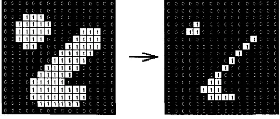
a) Opening
The basic effect o f an opening is somewhat like erosion in that it tends to remove
some ragged edges o f regions o f foreground pixels. Although erosion can be used to
eliminate small noise spikes quite effectively, it has the big disadvantage that it will
affect all regions of foreground pixels. Opening gets around this by performing both erosion and a dilation on the image. Opening can eliminate small noise spikes without
changing its orientation and size. All pixels covered by the structuring element within
the foreground region will be preserved. However, all foreground pixels that cannot
be reached by the structuring element will be eroded away. The effect o f an opening
on a binary image using a 3x3 square structuring element is illustrated in Figure 2.7
(cited from [GW]).
Figure 2.7 Effect o f opening using a 3*3 square structuring element
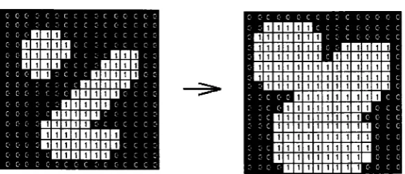
b) Closing
Closing is similar in some ways to dilation. Closing is opening performed reversibly.
It is defined simply as a dilation followed by an erosion using the same structuring
element for both operations. It tends to enlarge the boundaries o f foreground regions
in an image (and shrink background color holes in such regions), but it is less
destructive of the original boundary shape. Although dilation can fill in small
background holes in images, it will also distort all regions. Closing can have same effect without changing its orientation. For any background boundary point, if the
structuring element can be made to touch that point, without any part o f the element
being inside a foreground region, then that point remains background. The effect o f a
closing on a binary image using a 3x3 square structuring element is illustrated in
’ l> ' it I) } ) It > It I) It It It It
<t n n it t t it t • n n * ■ ■ it n n u > t it t kiqi> ' 't a t it t it 11 it n i i u it ■ it it it t n * i n n t it t it n
it t it 1 1 it n t it n o n
>
tnnnn n • ddd
• n n n n t n n n n n n1
tnnnn ■ n ■ ‘
it n a 10 p i it t n t it i
n it t it n nn t >
• ■
■
it n <t t t nnn ■ •c an t 11nnn ■ n ■
tnnn ■ > nn ■ »
it nnnnnn t ■
it t , .
i) o i } i> ■} ■) r. ) > ... i> :• :) i>
m
H H I Hi]
. . . I. DDDDDDD ■
t nnnnnnnnnnD
tnnnnnnnnDnn t
nnnnnnnna ■it n t >t t nnnnn °
1
■
1
■
■
itn t . t tnnnn t t • • .n • . . . nnn > ■ ■ ■
n n t 11 tnnn n n t ■
nnn ■ t nn . . .
. it nnnnnn
1
t . . . . .
I- I> J 1> ) ) :« I) i Ij i Ij D ij I)
Figure 2.8 Effect o f Closing using a 3 ><3 square structuring element
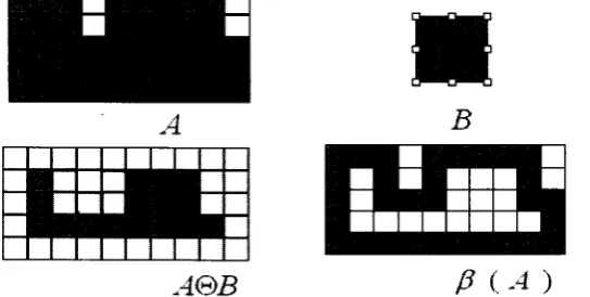
2.5 Boundary Extraction
When dealing with binary images, the principal application of morphology is
extracting image components that are useful in the description o f shape. In particular,
we consider morphological algorithms for extracting boundaries. Here we give detail
introduction about boundary extraction. The images are binary, with l ’s shown
shaded and 0’s shown in white. The boundary of a set A is obtained by first eroding A
by structuring element B and then taking the set difference o f A and it’s erosion. The
resulting image after subtracting the eroded image from the original image has the
boundary o f the objects extracted. The thickness o f the boundary depends on the size
of the structuring element B. The boundary of a set A denoted by (where B is a
suitable structuring element):
P(A) = A - ( A&B)
The effect o f boundary on image A using structure B is illustrated in Figure 2.9 cited
from [GW],
B
g a m
A@B
P
(-4
)2.6 Conclusion
In this chapter, we have established the necessary background for object detection and
tracking. Some basic methods and techniques in computer vision, including Camera
Calibration, Three-dimensional Reconstruction, Foreground segmentation, Boundary
Extraction and some Image morphological operations used to eliminate image noise,
Chapter 3
Tracking System Approach
The Object Tracking system recognizes and tracks interesting objects from image
sequences. In general, object-tracking system usually consists of four steps
(Figure3.1): pixel difference step, object detecting, object tracking and post
processing. In pixel difference step, systems extract the foreground images including
object images, from the static background image. Next, in object detection, they
extract object blobs (which stand for interest objects, such as human, car) from the
extracted foreground images based on the physical position o f each blob. Pixels
whose velocity and position are close to each other are grouped as a blob. Using
several blob features can identify each extracted blob. Object tracking stage compacts
groups of pixels, identifies the blobs, and tracks the identified blobs over time.
Finally, in post processing, they output some results o f the object blobs according to
different requirement such as people number, object trajectory and so on. The use of
Image
/
/
Image /Image Difference
Removing Noise
— I...
Blob O sculating Feature Feint
Object Tracking O bject M atching j'^Came ra' C glib'ration** j o b ject Recon*traction "1
Object Trajectory
Pixel Difference (Interest
Region)
Object
Object Tracking
"blobs" as a representation for image features have a long history in computer vision.
The term has had many different mathematical definitions. As we use it, a blob is a
compact set of pixels that share some visual properties such as intensity that are not
shared by the surrounding pixels. Now we will introduce all these four steps in detail:
3.1 Pixel Difference Method
In many video surveillance applications, cameras are fixed and we are interested in
tracking the motion of the foreground object, which could be people or cars. Pixel
Difference Method detects possible moving regions. The detection will depend on
motion o f the target and image subtraction. Pixel Difference Method is a particularly
efficient and sensitive method for detecting gray level changes between images
sequences. It is widely used in motion detection, where a fixed camera is used to
observe dynamic events in a scene.
The pixel difference method usually works as follows:
1) Select a threshold value m
The light radiation and frame grabber leads to the formation of noise in the input
images, which destroys the efficiency of the tracking system. In order to efficiently
detect within the viewing area o f the camera; the system requires a threshold value.
This threshold value can be calculated by computing the average of apparent
differences between two consecutive still images.
2). Scan every pixel in the two images and compute the pixel difference between the
pixel of the previous image and the same location pixel o f the current image. This
inter-frame difference image indicates where some movement has occurred.
3). If the difference is greater than the threshold value m, make it 0 (black). If the
difference is less than m, make it 255 (white). So all pixels o f the difference image
that have value O(black) include motion and probably belong to an moving object, whereas the pixels with value 255(white) that are not part o f the moving objects can
be ignored. In this way, moving region will be separated from background.
3.1.1 Frame Difference
Many video segmentation algorithms use Frame Difference as their primary
segmentation criterion. The position and shape of the moving object is detected from
the frame difference o f two consecutive frames. In our Fish-Tracker System, we used
Frame Difference method. Rosin in [RE95J has pointed out the disadvantages of change detection : 1) Only the motion “wavefront” will produce any change, so that
only part of the moving object is highlighted. 2) Objects that become stationary for
short periods of time will “disappear”. The alternative is Background Subtraction,
which is the technique that depends on the difference of the current frame with the
scene background. But extracting the background image from sequences o f frames is
needed.
3.1.2 Background Subtraction
Background Subtraction is the technique that depends on the difference between the
current frames with the scene background. But extracting the background image from
sequences o f frames is needed. Obviously, frame difference only gives us a rough
idea of which regions may contain moving objects, but it will not output good
tracking results. Background segmentation is a technique that the foreground region
can be separated from background by maintaining a background model, and
classifying each pixel into either foreground or background. The assumption here is
that the camera is more or less fixed such that we can maintain or train a background
model. In our Human-Counter System, we used Background Segmentation method.
P. L. Rosin and T. Ellis in [RE95] state that Background segmentation Method may be sub-divided into three parts: first, the generation o f a suitable reference or
background; secondly, the arithmetic subtraction operation; and thirdly, the selection
o f a suitable threshold. Background images can be generated by a variety o f methods.
For each image pixel location, we compare the input image pixel and its background
model and determine its class.
Some background models are as follows:
1. Mean: a simple approach in [RE95] [LJH][BK] just uses a median filter (average pixel value of whole image) at each pixel to generate background. Y.H. Yang and
estimate. For each pixel, a mean pixel is used to represent the background, i.e., the
background at some specific time is B (x; y). To check if an input pixel I (x; y) is a
foreground pixel or not, we just check
(I(x; y) - B (x; y))> Tor not. Where T is a threshold value.
2. Mean & Covariance: For each pixel, a Gaussian can be used to model the distribution of such pixel, i.e., the model for a background pixel is represented by a
mean pixel B (x; y) and its covariance C (x; y). To check an input pixel I (x; y), the
Mahalanobis distance is used, i.e., a foreground pixel satisfies:
[7(x; y) - B(x;y)] C(x; y)[I(x; y) - B(x; y ) ] > T. Where T is a threshold value.
R'omer Rosales and Stan Sclaroff in [RS98J use Mean & Covariance as background model.
3. Temporal Deviation: Since the computation o f the mixture of Gaussian model is a bit intensive, the temporal deviation model has a simple representation. For each
pixel, we maintain its minimum M (x; y), its maximum N (x; y), and the largest
interframe absolute difference D (x; y).A foreground input pixel I (x; y) will satisfy
(M(x; y) - I(x; y)j > D(x; y) or (N(x; y) - I(x; y)J > D(x; y).
In [HHD98], W4 system uses Temporal Deviation as background model.
3.2. Removing noise and Foreground Blob computing
Pixel Difference provides an estimate of the similarity with the background at every
pixel. Then, if a region of the image is dissimilar enough to the estimated empty
region, the system marks it as an interesting region.
Pixel Difference alone, however, is not sufficient to obtain clear foreground regions;
it results in significant level of noise due to illumination changes that should be
eliminated first. In [HHD98J, W4 uses region-based noise cleaning to eliminate noise regions. After background subtraction, one iteration o f erosion is applied to
foreground pixels to eliminate one-pixel thick noise. Then, a fast binary connected-
component operator is applied to find the foreground regions, and small regions are
eliminated. In [RS98J, a binary map of the current frame is computed with the interest regions in it. Then basic image morphological operations are applied (erosion-
interest. In [LJH], after binarizing the image derived from background subtraction, a filter is applied to the image to get rid of the noise. Then, a fast connected-component
operator is applied to the image to locate the foreground regions. The operator assigns
a clustering label to each pixel according to the labels of its upper-left and left
neighbors. After this self -clustering procedure, small regions are eliminated, and big
regions are considered as interesting objects.
A blob can be described as a set of connected pixels that share a common attribute. In
object tracking, pixels whose velocity and position are close to each other are grouped
as a blob. We identify each extracted blob by using several blob features. There are
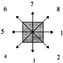
several techniques to cluster and extract blobs, such as “meandering process”[R97J,
“Fill procedure”/S P 7 / and “Neighborhood structure-Region growing algorithm”
[BR02J.
6 8
5
4 ?
3
Figure 3.2. Meandering algorithm
In [R97] (Figure 3.2), meandering algorithm works as follows. The blob analysis algorithm begins by scanning across the image pixels from left to right, top to bottom.
When a black pixel is located, it will be considered a new possible object and the
algorithm will meander through all continuously connected black pixels. We will look
in the eight directions to see if there is a black pixel that is connected to this one.
When all the black pixels within a region have been found, the minimum bounding-
box (blob) that can cover the region will be calculated. This process can extract the
foreground blobs, including human blobs.
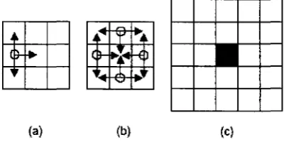
In [BR02], the method is a sort o f region growing algorithm. The objective o f this
method is to give a measure o f how much a pixel belongs to a structural windowed
region around it. The first step is to define the basic structure (Fig.3.3.a). And then
perform a logical “AND” between the pixels pointed by the circle and each one o f its
example, the kernel of Fig.7.b is applied to the 9 different sub-windows of Fig.7.c,
and the value o f the central pixel (the black pixel in Fig.3.3.c) is increased by the
outcome o f all these “AND” operations. Finally, this allows extracting the chain code
representing borders and use contour lines instead o f bounding boxes to highlight
blob.
4i cb if
(a) (b) (c)
Figure 3.3. Neighborhood structure-Region growing algorithm
3.3 Object Type Classification
After segmenting a foreground object from background in image sequences, we need
to classify objects into different categories such as human, vehicles using shape, color
analysis. Recognition techniques based on matching are usually adopted. An unknown
pattern is assigned to the class to which it is closest in terms of a predefined metric.
As stated in [GW], the simplest approach is the minimum-distance classifier, which computes the (Euclidean) distance between the unknown and each of the prototype
vectors. It chooses the smallest distance to make a decision. Another approach based
on correlation can be formulated directly in term of images and is quite intuitive. In
addition, probability considerations become important in pattern recognition because
of the randomness under which pattern classes normally are generated. So an
Optimum Statistical Classifiers approach can also be derived. It is optimal in the sense
that, on average, its use yields the lowest probability of committing classification
errors. Finally, neural networks involve architectures that consist o f layers of
perception computing elements and focus on decision functions of multi-class pattern
recognition, independent of whether or not the classes are separable.
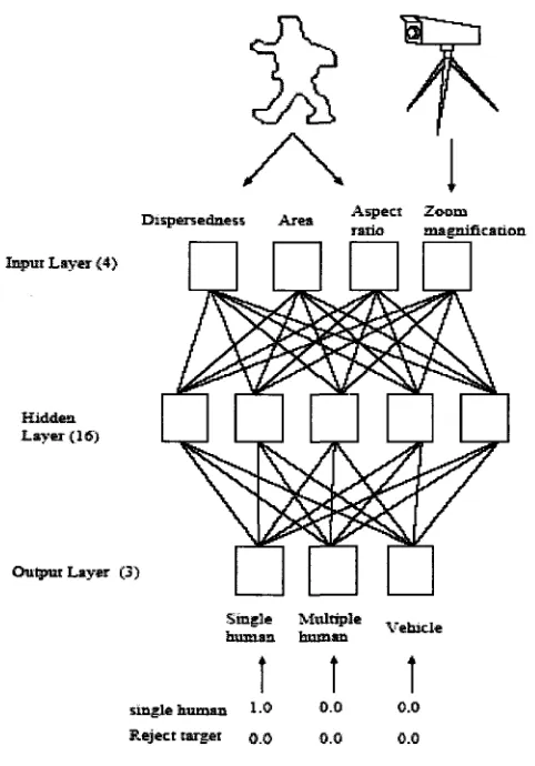
Collins in [CLOO] classifies moving object blobs into general classes such as “humans” and “vehicles” using viewpoint-specific neural networks, trained for each
camera. Each neural network is a standard three-layer network (Figure 3.4). They use
classes: single human; human group and vehicles. Learning in the network is
accomplished using the back propagation algorithm. Input features to the network are
a mixture of image-based and scene based object parameters: image blob
dispersedness (perimeter/area (pixels)); image blob area (pixels); apparent aspect
ratio o f the blob bounding box; and camera zoom. There are three output classes:
human, vehicle and human group. When teaching the network that an input blob is a
human, all outputs are set to 0.0 except for “human”, which is set to 1.0. Other classes
are trained similarly. If the input does not fit any o f the classes, such as a tree blowing
in the wind, all outputs are set to 0.0. This neural network classification approach is
fairly effective for single images; however, one o f the advantages of video is its
temporal component. To exploit this, classification is performed on each blob at every
frame, and the results o f classification are kept in a histogram. At each time step, the
most likely class label for the blob is chosen.
T arg et C am era
4 \
D ispersedaess A rea A sp ect Z oom ratio m ag n ific atio n In p u t L a y e r <4>
Hidden. L a y e r { 16)
O u tp u t L ay er (3)
Single M ultiple v
human human
t
t
1
cmglfr human 1.0 0.0 0.0
R e je ct target q q o.O 0.0