ISSN (Online): 2319-8753 ISSN(Print) : 2347 - 6710
International Journal of Innovative Research in Science, Engineering and Technology
An ISO 3297: 2007 Certified Organization Volume 6, Special Issue 7, April 20175th National Conference on Trends in Automotive Parts Systems and Applications (TAPSA-2017) 30th & 31st March 2017
Organized by
Sri Krishna College of Engineering & Technology, Kuniamuthur, Coimbatore-641008, Tamilnadu, India
PASSIVE CAR CABIN COOLING SYSTEM
Maheswaran. K.G1*, Sriram.M2, Tarun Kumar.S2, Yogesh.JR S2,
1Associate Professor, Department of Mechanical Engineering, KCG College of Technology, Chennai, Tamil Nadu,
India1
2Final year UG student, Department of Mechanical Engineering, KCG College of Technology, Chennai, Tamil Nadu,
India2
ABSTRACT: In today‟s world, cars are the most important form of transportation for an individual besides the public transport. The number of vehicles on the road is increasing on a daily basis and drivers experience difficulty in getting an indoor or roof parking space especially during peak hours. As a result, they have no choice except to leave their car in an open space parking. Under such circumstances, temperature inside the car increases. This causes the car to heat up and creates an intense sense of discomfort for passenger when they get inside the car later. As a solution for this deplorable condition, a passive car cabin cooling system is proposed. The purpose of this passive cabin cooling system is to help cool off the cabin of the car parked without a shade. Thus, the aim of this project is to develop a product that is capable to cool the passenger cabin without operating the car's engine, using a highly efficient kind of heat exchangers known as heat pipes. A heat pipe is an evaporation-condensation device for transferring heat in which the latent heat of vaporization is utilised to transport heat over long distances with a corresponding small temperature difference. The advantage of using a heat pipe over other conventional heat exchange methods is that large quantities of heat can be transported through a small cross-sectional area over a considerable distance with no additional power input to the system. Materials used are also of low cost and has high durability. This car cooling system is used to maintain the temperature inside the car at ambient temperature even under very hot conditions. As a result, once the user starts the car, the air conditioner doesn‟t have to work too hard in order to bring the temperatures to a comfortable level.
KEYWORDS: Heat pipes, Thermosyphon, Passive device, Thermal radiations, Heat exchanger.
І.INTRODUCTION
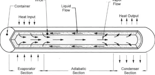
Figure 1: Schematic of the heat pipe
II. GEOMETRICAL CONFIGURATIONS
The heat pipe design is an iterative process and the selections or calculations are usually repeated several times. Depending upon the space restrictions of the car, several different configurations of heat pipe can be manufactured. Table 1 gives the design requirements of the heat pipe and Figure 2 gives the heat pipe geometry and dimensions.
Table 1: Design requirements of heat pipe
Design type
Heat pipe length (lhp)
1:2:1 10.16 cm
Evaporator length (le) 02.54 cm
Condenser length (lc) 02.54 cm
Adiabatic length (la) 05.08 cm
Outer diameter of heat pipe (do) 01.58 cm
Inner diameter of heat pipe (di) 01.39 cm
Wall thickness (tw) 00.17 cm
Vapor space radius (rv) 00.69 cm
Surface area of heat pipe (Ahp) 01.53 cm2
Area of vapor space (Avs) 00.38 cm2
Capacity (Q) 300.0 W
ISSN (Online): 2319-8753 ISSN(Print) : 2347 - 6710
International Journal of Innovative Research in Science, Engineering and Technology
An ISO 3297: 2007 Certified Organization Volume 6, Special Issue 7, April 20175th National Conference on Trends in Automotive Parts Systems and Applications (TAPSA-2017) 30th & 31st March 2017
Organized by
Sri Krishna College of Engineering & Technology, Kuniamuthur, Coimbatore-641008, Tamilnadu, India
Figure 2: Heat pipe geometry and dimensions
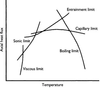
Figure 3: Operating limits of the heat pipe
A.Viscous Limit
The vapor pressure difference between the evaporator and condenser end is very small at low temperatures, then the viscous forces may be dominant. During startup when the temperatures are low, the dominant viscous forces prevent the operation of the heat pipe until the working range is achieved. The criteria for the consideration of viscous limit is given by (1)
(∆Pv/Pv) < 0.1 (1)
Viscous limit is of minimal importance for normal temperature applications according the Handbook of heat transfer.
B.Sonic Limit
The sonic limit is to be considered at the minimum working temperature. Equation (2) is used to calculate sonic limit
qs ρVL γVRTV (2)
2(γV 1)
Table 2: Sonic Limit Heat Flux
Water 1.448 KW/cm2
Methanol 5.870 KW/cm2
Acetone 4.660 KW/cm2
ISSN (Online): 2319-8753 ISSN(Print) : 2347 - 6710
International Journal of Innovative Research in Science, Engineering and Technology
An ISO 3297: 2007 Certified Organization Volume 6, Special Issue 7, April 20175th National Conference on Trends in Automotive Parts Systems and Applications (TAPSA-2017) 30th & 31st March 2017
Organized by
Sri Krishna College of Engineering & Technology, Kuniamuthur, Coimbatore-641008, Tamilnadu, India
Table 3: Sonic Limit Heat Flux
Water 9.000 K
Methanol 0.717 K
Acetone 0.690 K
The calculated values of degree of superheat for the three choices of working fluid are given in table 3. Preference must be given to those fluids that have the highest degree of superheat since the chances of boiling in the wick will be reduced. In our case water gets the first preference as the working fluid followed by methanol and acetone.
D. Entrainment Limit
The entrainment limit is evaluated at maximum temperature of operation and is given by (4)
qent πrv2 2πVσl (4)
L z
Table 4: Entrainment limit
Water 15786.20 W
Methanol 10917.34 W
Acetone 7401.33 W
The heat pipe has a circular cross section and is required to transport 300 W. Comparison with the entrainment limitations as given in table 4; we can see that the limit is not going to be reached for the fluids.
E.Capillary Limit
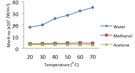
The performance of the working fluids can be evaluated by the Merit Number. The formula for evaluating merit number is given by (5). The Merit number for different fluids are shown the figure below
ρl(σμllL) (5)
Figure 4: Chart displaying the merit number of different working fluids
Figure 5 shows the experimental setup of the heat pipe. The adiabatic section and the protruding ends of condenser and evaporator section are insulated by means of glass wool. Figure 6 shows the front view of the heat pipe setup and Figure 7(a) shows the close up view of evaporator section, Figure 7(b) adiabatic section and Figure 7(c) the condenser section.
Figure 5: Experimental setup
0 10 20 30 40
20 30 40 50 60 70
M
er
it
n
o
(
x10
7 (
W
/m
)
2)
Temperature (O C)
Water
Methanol
ISSN (Online): 2319-8753 ISSN(Print) : 2347 - 6710
International Journal of Innovative Research in Science, Engineering and Technology
An ISO 3297: 2007 Certified Organization Volume 6, Special Issue 7, April 20175th National Conference on Trends in Automotive Parts Systems and Applications (TAPSA-2017) 30th & 31st March 2017
Organized by
Sri Krishna College of Engineering & Technology, Kuniamuthur, Coimbatore-641008, Tamilnadu, India
Figure 7(a): Evaporator, Figure 7(b): Adiabatic, Figure 7(c): Condenser
Three thermocouple wires are connected to the heat pipe, one for each region, and the other end to a multipoint scanner for temperature measurement. The voltage is controlled by means of a voltmeter to provide a supply power of 18W. Three sets of temperature readings were taken and the average of them is tabulated in table 5.
Table 5: Experimental results
Evaporator temperature Adiabatic temperature Condenser temperature Ambient temperature
65°C 45°C 42°C 40°C
Figure 8: Installed heat pipe system
III. CFD ANALYSIS OF HEAT PIPE
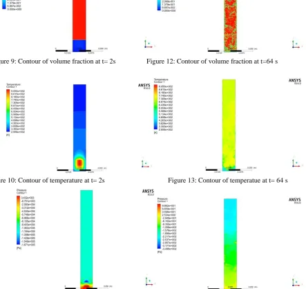
Figure 9: Contour of volume fraction at t= 2s Figure 12: Contour of volume fraction at t=64 s
ISSN (Online): 2319-8753 ISSN(Print) : 2347 - 6710
International Journal of Innovative Research in Science, Engineering and Technology
An ISO 3297: 2007 Certified Organization Volume 6, Special Issue 7, April 20175th National Conference on Trends in Automotive Parts Systems and Applications (TAPSA-2017) 30th & 31st March 2017
Organized by
Sri Krishna College of Engineering & Technology, Kuniamuthur, Coimbatore-641008, Tamilnadu, India
Table 7: Comparison between experimental and CFD results Section Position TEXP (°C) TCFD (°C) RE (%)
Evaporator Te 65 60 8.33
Adiabatic Ta 45 53 17.77
Condenser Tc 42 40 5.00
The convergence criteria of the scaled residuals were in the order of 10-4. The entire simulation took two months to be completed due to the excessive computational effort that is required. Steady state was reached around 1.067 minutes. The volume fraction of vapor phase, the temperature and pressure at the beginning and the end of simulation are displayed above. Three thermocouple wires were connected in the car, one to measure the ambient temperature, one to measure the temperature of the car cabin and the other to measure the temperature of the heat pipe. Fig. 8 shows the installed heat pipe on the car. As it can be seen, the evaporator is located below the roof of the car while the condenser is located above the roof of the car.
Table 8: Results after installing heat pipe
Before heat pipes After heat pipes
Peak inside temperature
40°C Peak inside temperature
43°C Ambient
temperature
19°C Ambient
temperature
38°C
∆T 19°C ∆T 5°C
VI. CONCLUSION
The following conclusions are drawn from the studies conducted.
1. The heat pipe system, its materials and fabrication were easily and commercially available at a low cost. 2. The total temperature drop of the heat pipe was 6° C
3. The heat pipe system reached steady state around 64 s 4. The final temperature drop inside the car cabin was 5° C
5. Distilled water was found to be excellent working fluid for copper heat pipes.
6. The presence of mesh inside the heat pipe ensured sufficient capillary pressure for the return of working fluid under inclined orientation.
7. Thus, heat pipes were found to be efficient heat transfer devices for car cabin cooling system.
ACKNOWLEDGMENT
I would like to thank Dr. S Ramesh, Professor and HoD of mechanical engineering department, KCG College of Technology, Chennai for his valuable support to develop this project.
REFERENCES
[1] H. Hussain Al-kayiem, B. Noble, and I.N. Sneddon, “Study on the thermal accumulation and distribution inside a parked car cabin,” American
[2] A.S Annamalai, V. Ramalingam, “Experimental Investigation and computational fluid dynamics of a air cooled condenser heat pipe,” Thermal Science, vol. 15, 2011, pp.759-772.
[3] R. Kempers, D. Ewing and C.Y. Ching, “Effect of number of mesh layers and fluid loading on the perfromance of screen mesh wicked heat
pipes,” Applied Thermal Engineering, Science Direct, vol. 26, 2006, pp. 589-595.
[4] J. Leigierski, B. Wiecek and Gilbert de Mey, “Measurements and simulations of transient characteristics of heat pipes,” Microelectronics
Reliability, Science Direct, vol. 46, 2006, pp. 109-115.
[5] B. Fadhl, C. Luiz Wrobel and H. Jouhara, “Numerical modelling of the temperature distribution in a two-phase closed therosyphon,” Applied
Thermal Engineering, Science Direct, vol. 60, 2013, pp. 122-131.
[6] C.K. Schepper, J. Heynderickx and B. Marin, “Modeling the evaporation of a hydrocarbon feedstock in the convection section of a steam
cracker,” Computers and Chemical Engineering, Elsevier, vol. 33, 2009, pp. 122-132.
[7] N. Putra, N. Septiadi and Ridho Irwansyah, “Thermal performance of screen mesh wick heat pipes with nanofluids,” Experimental Thermal and
Fluid Science, Elsevier, vol. 40, 2012, pp. 10-17.
[8] Per Wallin, “Heat pipe, selection of working fluid ,” Energy Sciences, Lund University, Sweden, 2012.
[9] S.M. Peyghambarzadeh, S. Shahpouri, N. Aslanzadeh and M. Rahimnejad, “Thermal performance of different working fluids in a dual diameter
circular heat pipe,” Ain Shams Engineering Journal, Elsevier, vol. 4, 2013, pp. 855-861.
[10] R. Kempers, A.J Robinson, D. Ewing and C.Y Ching, “Characterization of evaporator and condenser thermal resistances of a screen mesh