Determination of the Side and Front-rear
Buckling Loads for a Connecting-rod
Alejandro Esteban Rodríguez Sánchez1
Full Time Professor, Department of Academic Program, Automotive and Mechanical Engineering Program,
Universidad Politécnica de Chihuahua, Chihuahua, Chihuahua, México1
ABSTRACT:Buckling phenomena occurs in automotive connecting-rods when abnormal combustion takes place in the combustion chamber, this compromise their stability and ultimately the functionality of an Internal Combustion Engine. In the present study a numerical analysis, by means of a Finite Element model, was carried out to determine the two practical buckling loads for a connecting-rod.
KEYWORDS:Buckling, Critical Loads, Connecting-rod, Finite Element Method.
I. INTRODUCTION
The main purpose of a Piston Connecting-rod assembly of an Internal Combustion Engine (ICE) is to receive the pressure generated in the combustion chamber and transmit it, by means of a torque, to the crankshaft. The connecting-rod plays a key role in the aforementioned task, being important for it to complete the following functions: a) to be the link between the piston and the crankshaft, b) to transform the linear motion of the piston to rotational motion to the crankshaft, and c)to be strong enough to resist the main loading sources of the internal combustion process.
The design of connecting-rods for an ICE involves the analysis of yielding regions in the material of which they are manufactured, fatigue-life analysis and buckling analysis [1, 2, 3]. Also, because vibration plays a great factor among the design, vibrational analyses are important too in order to avoid resonance phenomena.
The recognition of the abovementioned analyses for connecting-rods gives to the engineers the knowledge to propose better optimizations in terms of weight reduction, cost reduction and better functionality [4-7]. Most of these optimization methodologies rely on the Finite Element (FE) method and reliability techniques to address enhanced designs.
Specifically, designs tolerant against buckling are relevant because pre-ignition, knocking, piston blocking or abnormal combustion could cause that the resulting pressures might be higher than the nominal in the combustion chamber, leading to a failure in the shank section of a connecting-rod.
The aim of the present work is to obtain, through a FE model, the critical loads of the two practical buckling modes for a connecting-rod which is planned to be used in an alternative ICE fuelled with hydrogen/gasoline mixture.
II. RELATEDWORK
As pointed out in [8], the shank section in a connecting-rod is subjected to compression due combustion pressure; this happens when the power stroke takes place in the combustion chamber. Buckling is a phenomena characterized by an excessive of these compression loads and is classified as anEuler-type collapse failure [8].
order to identify the cross sectional areas where excess of material existed; they proposed gradually change the cross-sectional area of the connecting-rod monitoring the buckling stress and critical loads. They concluded with an optimized geometry for a connecting rod in terms of weight reduction.
The present work deals with LEBin order to determine the buckling loads of a connecting-rod, therefore, the formulation of the referred technique is described in the next section. Then, the corresponding FE model for the buckling simulation of a connecting rod is detailed and its results are discussed in the final sections of this work.
III. LINEARELASTICBUCKLING
As mentioned earlier, excessive compression loads lead to structural instabilities in ICE connecting-rods. Such instabilities are characterized by critical loads which cause buckling. Fundamental theory of elastic buckling refers that the first elastic critical load for an ideal column is given by:
=
(1)
where is the effective length of column; is the elastic modulus of the material; is the moment of inertia for the normal section of the member. The critical load/s for a given connecting-rod cannot be calculated directly by the Eq. (1), because its effective length is not clearly defined from its extremities, i.e., for small end (upper) and big end (lower) supports, the boundary conditions are not the same as an ideal column; furthermore, connecting-rods have a variable cross section along the shank. Due the aforementioned reasons, Finite Element method arises as good technique to analyze and obtain the critical loads in complex-like geometries for connecting-rods.
FE Linear Elastic Buckling technique is based on the eigenvalue problem and serves to identify critical buckling loads. For a slender mechanical member under compression, being { } and { } the initial load and its displacement, their relationship is given by:
{ } = [ ]{ } (2)
where [ ] is the elastic stiffness matrix of the mesh generated through FE for the mechanical member (in this case the con-rod). Developing the eigenvalue problem, for a given increment {∆ } in the load, the Eq. (2) could be re-written as follows:
{∆ } = [ ] + [ ( )] {∆ } (3)
where {∆ } is the change in displacement as a result of the load increment and [ ( )] is the stiffness matrix evaluated at a given stress state .
Instability due to buckling is assumed when the system exhibits a change in displacement and, at the same, the load tends to zero, i.e.,{∆ }≈0. Thus:
[ ] + [ ( )] {∆ } = {0} (4)
where λ is the eigenvalue of the buckling load. Re-writing Eq.(4):
[ ] + [ ] { } = {0} (5)
where1 refers to a compression unit load applied in the FE model.
FE Linear Elastic Buckling was the technique used to obtain the buckling critical loads for the connecting-rod presented in this study.
IV. FEMODEL
A FE model was carried out in Abaqus® to obtain the critical loads of the front-rear y side buckling eigenmodes and eigenvalues of the connecting-rod shown in the Figure 1. The analysed connecting-rod corresponds to a 1781cc four cylinder engine.
Fig. 1. ICE Connecting-rod
SolidWorks® was used to model the geometry of the connecting-rod depicted in the Figure 1; this was done through reverse engineering that consisted on measuring a batch of 8 connecting-rods. The geometrical properties of the connecting-rod are presented in the Figure 2.
Fig. 2. Geometrical properties of the connecting-rod (all dimensions are in millimeters).
Property
Poisson’s ratio 0.29 Elastic Modulus 205 (GPa) Table 1: AISI 4140 mechanical properties.
The boundary conditions applied in the model consisted in fixing the lower big end of the connecting-rod and a vertical unit load = 1[N] was applied to the lower half inner cylindrical faces of the upper small end to obtain the eigenvalues and (see Figure 3 for reference).
Fig. 3. Boundary conditions.
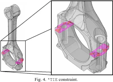
The figure 4 shows a surface-to-surface*TIE constraint that was considered to simulate the connection of the upper and lower big end parts of the connecting-rod. This was done to simplify the model because in a more sophisticated simulation, pre-stress could be needed along with plasticity (because the clamping force of the bolts stress the outer region of the lower big end).
Fig. 4. *TIE constraint.
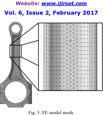
A mesh convergence study was performed to ensure that the critical buckling loads were reliable. The resulting mesh of the FE model consisted in 174,673 quadratic tetrahedral type C3D10 elements.
=
=
= 0
Fig. 5. FE model mesh.
The mesh, as it can be seen in the Figure 5, considered a general aspect ratio of 1:1 for all elements.
V. SIMULATIONANDRESULTS
The buckling eigenmodes are presented in the Figure 6 and the Figure 7. It can be noticed that the buckling shapes correspond to the presented in the literature [8, 9], i.e, virtual displacements in the side buckling mode happens in the small upper end of the connecting rod while for the front-rear buckling is observed in the upper part of the shank section.
Fig. 6. Side-buckling eigenmode. (a) Front view, (b) Isometric view.
Fig. 7. Front-rear buckling eigenmode. (a) Side view, (b) Isometric view.
In Figure 7 it can be seen that the front-rear buckling mode is a more complex mode in terms of displacements of the connecting rod:the maximum virtual displacement goes in the direction of the crankpin journal and gudgeon pin axes, while the small upper end depicts a combination of rotation and displacement in a plane that contains these axes.
Buckling load
Side buckling, , 3.22004E+05 (N) Front-rear buckling, , 4.67082E+05 (N)
Table 2: Buckling loads.
Regarding to the Table 2, front-rear buckling is approximately 45.04% higher than the side buckling mode. This states that re-design and safety factors against buckling should be driven by front-rear critical loads in order to prevent the two practical buckling modes.
VI. CONCLUSIONS
A FE Linear Elastic Buckling model was used to determine the two practical buckling modes and critical loads for a connecting-rod. The following conclusions are addressed in this work:
1. The FE method is a practical way to forecast the elastic buckling critical loads for a connecting-rod, it helps engineering design teams to recognize critical loads even before testing.
2. Because the presented work deals only with elastic behaviour, for further understanding of the buckling phenomena, it could be necessary to investigate how the plasticity and pre-stress affectthe loads presented in the Table 2.
3. It is recommended that the FE Linear Elastic Buckling approach presented in this work will be one of the first steps when buckling is critical for the design of connecting-rods.
4. Based on the results, a recommendation is that the designshould be focused in dealing with the critical loads regarding the front-rear mode.
REFERENCES
[1] Rabb, R., “Fatigue Failure of a connecting rod”, Engineering Failure Analysis, Vol. 3, pp.13–28, 1996.
[3] Ankhare, A.V., Dupare, Y.B., and Wagh, A.S., “Stress Analysis of Connecting Rod”, International Journal of Pure and Applied Research in Engineering and Technology, Vol. 1, Issue no.8, pp.250–260, 2013.
[4] Lee, H.J., and Lin, M.C., “Optimal shape design of engine connecting rod of with special lumping mass constraint”, JSME International Journal, Series C, Vol. 39, Issue no. 3, pp.597–605, 1996.
[5] Rao, N.M., “Design Optimization and Analysis of a Connecting Rod using ANSYS”, International Journal of Scientific and Research (IJSR),
Vol. 2, Issue no. 7, pp.225-229, 2013.
[6] Vazhappilly, C.V., and Sathiamurthi, P., “Stress Analysis of Connecting Rod for Weight Reduction – A Review”, International Journal of Scientific and Research Publications, Vol. 3, Issue no.2, pp.1-5, 2013.
[7] Pandey, N., and Nikaam, J., “Designing Stress Analysis of the Industrial Compressor Connecting Rod Depending Upon the Design Inputs
Using ANSYS Workbench”, International Journal of Innovative Research in Science, Engineering and Technology, Vol. 5, Issue no. 6, pp.9574–9583, 2016.
[8] Strozzi, A., Baldini, A., Giacopini, M, Bertocci, E., and Mantovini, S. “A repertoire of failures in connecting rods for internal combustion engines, and indications on traditional and advanced design methods. Engineering Failure Analysis”, Engineering Failure Analysis Vol. 60, pp.20–39, 2016.
[9] Lee, M.K., Lee, H., Lee, T.S., and Jang, H., “Buckling sensitivity of a connecting rod to the shank sectional area reduction”, Materials & Design, Vol. 31, Issue no. 6, pp.2796–2803, 2010.
[10] Dave, A., Mourya, R.M., and Bartariya, V. N., “Study of Connecting Rod to the Shank Sectional Area Reduction of Variable Cross Section by
using Finite Element Method”, International Journal for Scientific Research & Development, Vol. 3, Issue no. 2, pp.371-376, 2015.
[11] Kumar, P.S., and Kumar, K., “Buckling Analysis and Shape Optimization of a Connecting Rod using FEA”, REST Journal on Emerging