Behaviour of Flat Slab a Study by Finite
Element Analysis
Dr. K.N.Kadam1, Viquaar Shaikh2
Associate Professor, Department of Applied Mechanics, Government College of Engineering, Amravati, India1
P.G. Student, Department of Applied Mechanics, Government College of Engineering, Amravati, India2
ABSTRACT:Flat slabs system of construction is one in which beams are absent. In this types of the slab, load from the slab is directly transferred to the columns and then to the foundation i.e. the slab is directly supported on columns. As there is no beam present, the thickness of slab near the support of the column is increasedto support heavy loads. This increased thickness of the slab near the column is called as drops. The columns generally provided with enlarged heads called column heads or capitals are also used as an alternative. And sometimes due to more punching shear both drop as well as column capital is provided together. Due to ease of construction and its minimum depth, flat slabs has been widely used in the construction of buildings. A plain ceiling is formed due to the absence of beam, thereby giving a better architectural appearance. Plain ceiling diffuses light better, easier to construct and requires cheaper formwork.
Though many advantages, flat slab faces a major problem of punching shear. The brittleness of punching shear makes it the concern of structural engineer since it does not give any warning before failure. Hence in this research work, the behaviour of punching shear in the flat slab with drops, column capital, both drop & column capital together, grade of concrete and shear stud rails has been studied.Different models of the flat slab are analysed by Finite Element Analysis method using SAFE 2016. The punching shear behaviour has been studied and comparison among them has been done. However, the analysis of such a connection is rather complex and includes several challenges. Consequently, the punching strength depends on various parameters that have to be investigated individually.
Slab failure if predetermined can save the loss of lives, a proper analysis can help in proper designing which can enhance the performance of the structure.
KEYWORDS: Flat Slab, Punching Shear, Flat plate, Shear Strengthening.
I.INTRODUCTION
The flat slab is generally a type of two-way reinforced concrete slab in which the flooring slab is directly supported on columns without the agency of beam or girders. For span from 5 to 9m thin flat slabs are the preferred solution for the construction of in-situ concrete frame building, where a square or near square grid is used. Due to ease in construction and for the architectural view, flat slabs has been widely used in the construction of buildings. Though many advantages, flat slab faces a major problem of punching shear force acting at the slab-columnjunction. The punching shear force at the slab-column junction increases in this type of slab due to the transmission of vertical loads to the columns through the small thickness of slabs.
to the economical and architectural concerns. In such situations, placing shear reinforcementin the intersection of the flat slab-column system is a good solution to the brittle punching shear failure problem[5,2].Nonlinear finite element analyses of reinforced concrete slab-column connections under static and pseudo-dynamic loadings were conducted to investigate their failures modes in terms of ultimate load and cracking patterns[1].Finite-element analyses (FEA) of reinforced concrete slab-column connections with shear reinforcement are presented and discussed.Ultimate loads and crack patterns are shown and compared to the experimental findings[2].To date, a significant number of investigations have been conducted on strengthening existing slab to column connections for internal columns.The research investigates the effectiveness of strengthening flat slab to column corner connections by using carbon fibre reinforced polymer (CFRP) bolt[4].A strengthening of flat slabs using steel bolts can also be done[11].
II. SPECIMEN DETAILS AND MATERIAL PROPERTIES
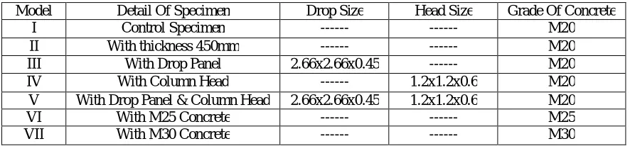
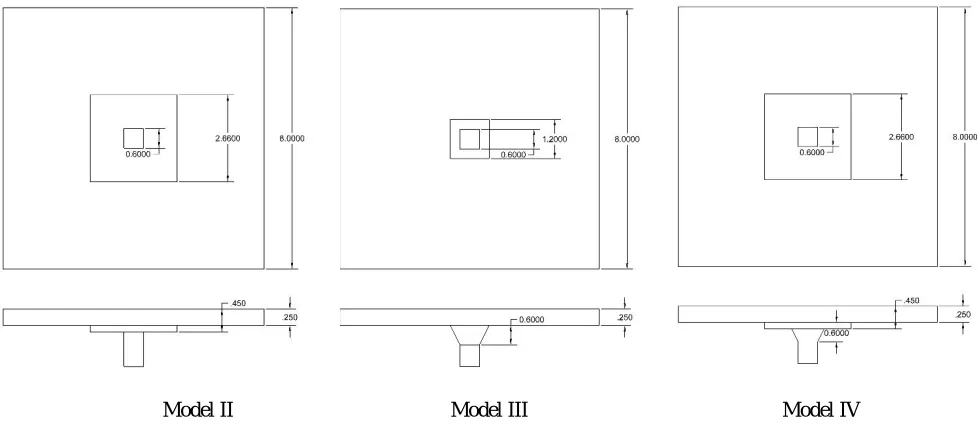
A flat slab model of having four bay in both the direction is considered which resembles with most of the commercial buildings. The slab is directly rested on column have the thickness of slab as 250mm. The size of the column is taken as 0.6mx0.6m. The size of each slab-panel is 8mx8m. The plan view of the model is given in Fig. 1. To ensure that punching shear takes place, no column capital nor drop panned is provided and nor any shear strengthening is done. The design of the Flat slab is done using CSI software SAFE2016 by Finite Element Method. Dead load of 6.25kN/m2 and live load of 4kN/m2floor finish of 1.5kN/m2and partition of 2kN/m2is applied on slab and factor of safety of 1.5 is applied to the total load. Thus, the total factored load applied on the slab is 20.625kN/m2. The clear cover of 15mm is provided at the bottom face as well as at top face of the slab. The grade of concrete used are M20, M25, M30 and grade of steel used is Fe415. Total 7 models are designed and analysed.
Table No. 1: Specimen details
Model Detail Of Specimen Drop Size Head Size Grade Of Concrete
I Control Specimen --- --- M20
II With thickness 450mm --- --- M20
III With Drop Panel 2.66x2.66x0.45 --- M20
IV With Column Head --- 1.2x1.2x0.6 M20
V With Drop Panel & Column Head 2.66x2.66x0.45 1.2x1.2x0.6 M20
VI With M25 Concrete --- --- M25
VII With M30 Concrete --- --- M30
Fig. 1: Plan view of the model
The drop of 2.6x2.6m and depth of 450mm is provided in the 2nd model. The column head of dimension 1.2x1.2m and depth of 600mm is provided in the 3rd model. In the 4th model, both drop panel, as well as column head, provided together. In the 5th model, we use the M25 grade of concrete and as well as the depth of slab is also increased. And in the last model, we use the M30 grade of concrete. For overcoming the punching shear we use the FE415 models. All the model has been analysed in finite element analysis based software SAFE 2016.
Model II Model III Model IV
III. NUMERICAL ANALYSIS
A three-dimensional finite element based program ‘SAFE' is used for the numerical analysis of seven flat slab models, one of them as control specimen and other models with different arrangements. In this analysis, the material is defined as M20, M25, M30 for the grade of concrete and Fe415 as the grade of steel. All the seven case are modelled and analysed by using the ‘Automatic slab mesh option' for the meshing of the slab. Minimum reinforcement ratio use for cracking is 0.12% as per IS 456. Since CSI SAFE is a designed based software the model/structure will not fail until the maximum percentage of steel reached the maximum permissible limit as per IS 456 i.e. 8%. Thus, in this software depending upon different arrangements the percentage of steel and the deflection is affected for all the seven case. Due to different arrangements the designed shear stress in the structure increases which results in the increment of punching shear ratio, where, punching ratio is,
PunchingShearRatio =MaximumDesignedShearStress
ShearStressCapacity
The shear stress capacity of the concrete is 1.118N/mm2 for M20 and 1.25 N/mm2 for M25 and 1.3693 N/mm2 for M30. The shear stress capacity depends upon the grade of concrete and the shear reinforcement provided. And the design shear stress i.e. nothing but punching shear depends on the grade of concrete, depth of concrete at that location and shear reinforcement. Since the punching shear changed by using different arrangements in this paper, the shear stress capacity is only due to concrete.
For, Punching Shear ratio ≤ 1 …………. (Implies the Structure/Model is safe)
Punching Shear ratio > 1 …………. (Implies the Structure/Model fails in punching) Depending upon above relation the following studies has been done.
IV. EFFECT ON PUNCHING SHEAR
Depending upon the load applied, the punching force varies abruptly. Punching shear occurs when the design/maximum shear stress at a point is more than shear stress capacity at the same point. Generally, the punching shear occurs due to localized forces. Since punching shear is a type of brittle failure the failure in the structure is sudden so it is more important to design the structure within permissible shear stress capacity.
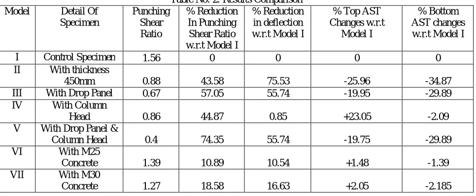
Table No. 2: Results Comparison Model Detail Of
Specimen Punching Shear Ratio % Reduction In Punching Shear Ratio w.r.t Model I
% Reduction in deflection w.r.t Model I
% Top AST Changes w.r.t
Model I
% Bottom AST changes w.r.t Model I
I Control Specimen 1.56 0 0 0 0
II With thickness
450mm 0.88 43.58 75.53 -25.96 -34.87
III With Drop Panel 0.67 57.05 55.74 -19.95 -29.89
IV With Column
Head 0.86 44.87 0.85 +23.05 -2.09
V With Drop Panel &
Column Head 0.4 74.35 55.74 -19.75 -29.89
VI With M25
Concrete 1.39 10.89 10.54 +1.48 -1.39
VII With M30
Total7 models have been analysed by finite element analysis using CSI software SAFE 2016 for the loading condition as per IS 875. It is observed that for this loading condition the punching shear capacity is very low since only flat slab plate of thickness 250mm is provided. In order to increase punching shear capacity so that structure should be safe, the depth of slab needed to be increased. The depth of slab require is 450mm in order to be safe in punching. Though the structure is safe in punching, the economy of the structure is highly affected. From above observation, we have noticed that the depth of 450mm of the slab is required at a slab-column junction only for increasing punching shear capacity. Hence in model III & IV, the punching shear ratio was calculated by providing drop panel & column head respectively. And the result obtained was positive i.e. punching shear capacity is considerably increased.
So in model V both drop panel, as well as column head, are provided together. And thus it shows the drastic change in punching behaviour of flat slab i.e. the punching shear is reduced to 74%. Which is the most effective & economical in this case. Thus model V should be used in critical cases. Further, the effect of the grade of concrete is also studied using M25 and M30 grade of concrete then the result shows the punching shear capacity of structure increase with respect to grade of concrete but the increase in the punching shear capacity is in the small amount. So this shows that the effect of drop panel with column head gives the much better results compared to other models.
From the result it was observed that for the specimen with both drop panel and column head together, the punching shear reduced drastically also it was observed the required percentage of steel was also reduced by 19.75%.
VI. CONCLUSIONS
This paper represents a numerical analysis of flat slab with different models. Without providing any shear reinforcement the results were obtained for all the seven cases so that the effect of depth on concrete & grade of concrete in the flat slab can be studied and compared among themselves. Based on the numerical results and discussions, the following conclusions are drawn,
i. The punching shear capacity of flat slab depends on the depth of flat slab at the slab-column junction. ii. The grade of concrete also affects the punching shear but in the small amount.
iii. The depth of slab is inversely proportional to the deflection in slab i.e. as the depth of slab increases the deflection decreases.
iv. The area of steel in the flat slab is inversely proportional to the depth of slab i.e. with an increase in the depth of slab, the area of steel required decreases.
v. The design punching shear is low in which both column drop and column head are provided together.
vi. It was observed that by increasing the depth of slab near slab column junction i.e. in punching area the punching capacity can be increased so there is no need to provide more depth throughout the section. Hence for optimisation purpose the more depth of slab is provided at punching area only.
REFERENCES
1. Aikaterini S. Genikomsou, Maria Anna Polak, “Finite element analysis of punching shear of concrete slabs using damaged plasticity model in ABAQUS” Elsevier. (2015).
2. Aikaterini S. Genikomsou, Maria Anna Polak, “Finite-Element Analysis of Reinforced Concrete Slabs with Punching Shear Reinforcement”American Society of Civil Engineers.(2016).
3. Long Nguyen-Minh, MariánRovňák and Toan Tran-Quoc, “Punching Shear Capacity of Interior SFRC Slab-Column Connections”
ASCE.(2012)
4. Ran Li, Young Sang Cho &Sumei Zhang, “Punching shear behavior of concrete flat plate slab reinforced with carbon fiber reinforced polymer rods” Elsevier. (2006)
5. Ashraf Mohamed Mahmoud, “Finite element implementation of punching shear behaviors in shear-reinforced flat slabs” Ain Shams Engineering Journal. (2015)
6. Hong-Gun Park, You-Ni Kim, Jin-Gyu Song and Su-Min Kang, “Lattice Shear Reinforcement for Enhancement of Slab-Column Connections”
ASCE. (2015)
7. Marko Bartolac, DomagojDamjanović& Ivan Duvnjak, “Punching strength of flat slabs with and without shear reinforcement.” JCE. (2015) 8. H. Erdoğan, G. Özcebe and B. Binici, “A New CFRP Strengthening Technique To Enhance Punching Shear Strength Of RC Slab-column
Connections” APFIS (2007)
10. Nicholas Lawler and Maria Anna Polak, “Development of FRP Shear Bolts for Punching Shear Retrofit of Reinforced Concrete Slabs” ASCE (2011).
11. Carlos Moreno, Débora Ferreira, AbdelkrimBennani, Ana Sarmento, and Michel Noverraz. “Punching Shear Strengthening Of Flat Slabs CFRP And Shear Reinforcement” (2015).