Dynamic Modeling of Multistring Inverter
with Multi Rated Models of Photovoltaic Cells
Tadi Asha kranthi
1, S Sruthi
2PG Scholar, Department of Electrical and Electronics Engineering, Sri Padmavathi Mahila Visva Vidyalayam, Tirupathi, Andhra Pradesh, India1
Assistant professor, Department of Electrical and Electronics Engineering, Sri Padmavathi Mahila Visva Vidyalayam, Tirupathi, Andhra Pradesh, India2
ABSTRACT: This paper presents the study of modeling of one stage multi string inverter with multi rated model of photo voltaic modules. As the name implies, the Multi string topology can able to handle more number of PV strings with different orientations and varied irradiation levels. This multi string inverter is capable to harvest the maximum possible power from each without depending upon orientation, irradiation level, and at different operating temperatures. In this paper a multi string inverter with two different PV modules using MATLAB/SIMULINK has been implemented and complete analysis is carried out with and without filters. THD of output is also obtained.
KEYWORDS: Multi string inverter, photo voltaic module, total harmonic distortion (THD), and filter.
I. INTRODUCTION
ISSN(Online): 2319-8753 ISSN (Print): 2347-6710
I
nternational
J
ournal of
I
nnovative
R
esearch in
S
cience,
E
ngineering and
T
echnology
(An ISO 3297: 2007 Certified Organization)
Website: www.ijirset.com Vol. 6, Issue 6, June 2017
Fig.1conventional configuration
In its conventional configuration, several strings are interfaced with their own MPP-tracked dc–dc converter to a common inverter as shown in Fig. 1. The multistring approach permits the combination of strings with different features with respect to the manufacturing technology, geographic orientation, and number of modules per string. It also provides the enhanced operation of the PV systems in partial shading conditions when the PV strings are at different irradiance levels and operating temperatures. The conventional multistring PV topology has the limitation of very low conversion efficiency due to two stages of power conversion and the use of several bulky limited-lifetime electrolytic capacitors in the main dc-link.
A soft switched one-stage multistring PV inverter with multi rated photo voltaic modules has been presented in this paper. Similar to the conventional multistring topology, the proposed inverter can handle an arbitrary number of PV strings with different electrical parameters and working conditions while obtaining the maximum possible power from each string independently. However, the proposed topology has a one stage of soft switched power conversion without electrolytic capacitor in the link. Therefore, this converter is estimated to have an improved efficiency, more power density, and enhanced reliability. The new inverter has an HFAC link, so a small-sized high-frequency (HF) transformer has been used to achieve galvanic isolation.
II. PV MODULE
Photovoltaic (PV) array which is integration of modules is considered as the basic power conversion unit of a PV generator system. The PV array has nonlinear characteristics and it is little expensive and takes more time to get the operating curves of PV array under varying operating conditions. In order to overcome these obstacles, common and simple models of solar panel have been developed and combined to many engineering softwares including Matlab/Simulink. However, these models are not adequate for application involving hybrid energy system since they need a flexible tuning of some parameters in the system and not easily understandable for readers to use by themselves. DS-100M solar panel is taken as reference model. The operation characteristics of PV array are also studied at a wide range of operating conditions and physical parameters.
disadvantage of these papers is lack of presenting simulation procedure so it causes difficulties for readers to follow and simulate by themselves later. T his disadvantage is filled in by (Jena et al. 2014), (Pandiarajan and Muthu 2011). A step-by-step procedure for simulating PV module with subsystem blocks with user-friendly icons and dialog in the same approach with Tarak Salmi and Savita Nema is developed by Jena, Pandiarajan and Muthu et al. However, the biggest gap of the studies mentioned above is shortage of considering the effect of partially shading condition on solar PV panel’s operation. In other researches, authors used empirical data and Lookup Table or Curve Fitting Tool (CF tool) to build P–V and I–V characteristics of solar module (Banu and Istrate 2012). The disadvantage of this method is that it is quite challenging or even unable to collect sufficient data if no experimental system be available so that modeling curves cannot be built and modeled. From the work of (Ibbini et al. 2014) and (Venkateswarlu and Raju 2013), a solar cell block which has already been built in Simscape/Simulink environment is employed. With this block, the input parameters such as short circuit current, open circuit voltage, etc. is provided by manufacturers. The negative point of this approach is that some parameters including saturation current, temperature, and so on cannot be evaluated. Solar model developed with Tag tools in Simulink environment is recorded in the research of (Varshney and Tariq 2014), (Mohammed 2011), etc. In these papers, only two aspects (solar irradiation and temperature) are investigated without providing step-by-step simulation procedure.
•• previous models are insufficient to study all parameters which can significantly affect to I–V and P–V characteristics of solar PV array, including physical parameters such as saturation current, ideality factor, series and shunt resistance, etc. and environmental working conditions (solar isolation, temperature and especially shading effect).
•• The proposed model shows strength in studying all parameters’ influence on solar PV array’s operation. In addition, a unique step by-step modeling procedure shown allows readers to follow and simulate by themselves to do research. The equivalent circuit of a PV cell is shown in Fig. 1. The current source Iph
represents the cell photocurrent. Rsh and Rs are the intrinsic shunt and series resistances of the cell, respectively.
Usually the value of Rsh is very high and that of Rs is very small, hence they may be neglected to simplify the
analysis (Pandiarajan and Muthu 2011). Practically, PV cells are grouped in larger units called PV modules and these modules are connected in series or parallel to create PV arrays which are used to generate
electricity in PV generation systems. The equivalent circuit for PV array is shown in Fig. 2.
The voltage–current characteristic equation of a solar cell is provided as (Tu and Su 2008; Salmi et al. 2012): Pv cell output
voltage is given by
V
C=
AkTC𝒒
ln [
Iph+I0-Ic
I0
] - R
sI
cModule photo-current Iph:
Iph = [Isc + Ki(T − 298)] × Ir/1000
Here, Iph: photo-current (A); Isc: short circuit current (A) ; Ki: short-circuit current of cell at 25 °C and 1000 W/m2; T: operating temperature (K); Ir: solar irradiation (W/m2). Module reverse saturation current Irs:
Irs = Isc/[exp(qVOC/NSknT) − 1]
Here, q: electron charge, = 1.6 × 10⁻¹⁹C; Voc: open circuit voltage (V); Ns: number of cells connected in series;
n: the ideality factor of the diode;
ISSN(Online): 2319-8753 ISSN (Print): 2347-6710
I
nternational
J
ournal of
I
nnovative
R
esearch in
S
cience,
E
ngineering and
T
echnology
(An ISO 3297: 2007 Certified Organization)
Website: www.ijirset.com Vol. 6, Issue 6, June 2017
Fig. 2 PV cell equivalent circuit (Salmi et al. 2012)
Fig. 3 Equivalent circuit of solar array (Tu and Su 2008)
Tc-- reference cell operating temperature (20 oC)
VC-- cell output voltage (V)
Equation of VC is validated for specific temperature and solar irradiation level. Said so, under a new cell temperature
and a new solar irradiation level, the output voltage and the cell photocurrent would become,
Vc_new=CTVCSVVC
Iph_new=CTICSIIph
Where, CTV, CSV, CTI and CSI are correction coefficients whose values are dependent on
The cell temperature and the solar irradiation level
Reference model:
The 100 W solar power modules is taken as the reference
Module for simulation and the detailed parameters of module is given in Table below
Electrical characteristics data of DS-100 M PV Module:
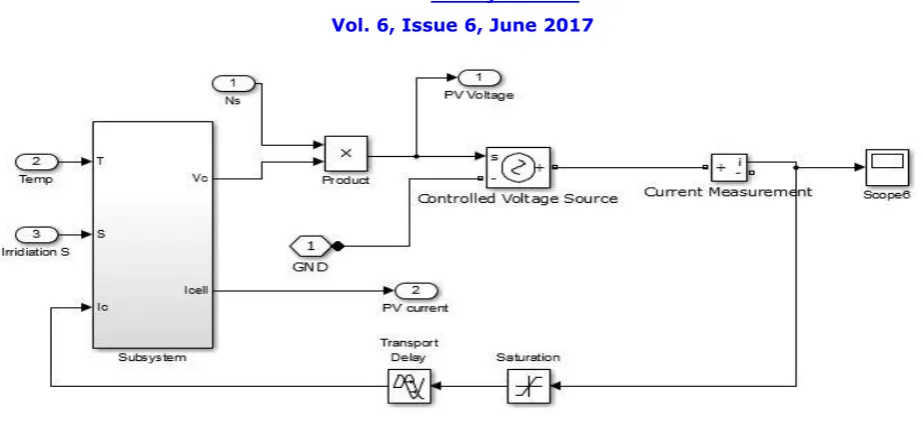
A mathematical model of PV array including fundamental components of diode, current source, series resistor and parallel resistor is modeled with Tags in Simulink Environment (http://mathwork.com). The simulation of solar module is based on equations given in the section above.
Fig.4 Solar subsystem Simulink design
Name DS-100M
ISSN(Online): 2319-8753 ISSN (Print): 2347-6710
I
nternational
J
ournal of
I
nnovative
R
esearch in
S
cience,
E
ngineering and
T
echnology
(An ISO 3297: 2007 Certified Organization)
Website: www.ijirset.com Vol. 6, Issue 6, June 2017
Fig. 5 Solar module Simulink design
III. SOFT SWITCHED MULTI STRING INVERTER
The soft-switched multistring PV inverter with multi-rated PV source is shown in Fig. 4. The number of the input PV strings as well as their characteristics, operating voltages, and power levels is completely random. The proposed inverter can individually collect the maximum possible power of each string regardless of its location, orientation, irradiation level, or operating temperature. A capacitor is placed on primary side of the transformer for soft switching and to behave as passive snubbers as well. In this way, they provide paths for the leakage inductance currents of the transformer when the switches are turned OFF and avoid voltage spikes.
Fig.6 proposed soft switched multi string inverter
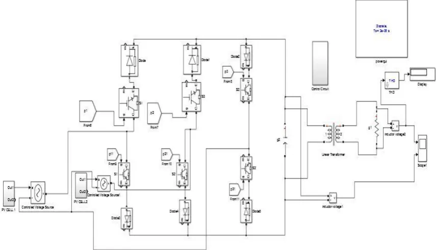
The converter needs to have two reverse-blocking switches for each PV string in addition to two more reverse-blocking switches for the return leg. A reverse-blocking switch can be realized by a conventional IGBT or MOSFET in series with a diode. The newly available individual reverse-blocking switches can also be employed with
A. Control Strategy
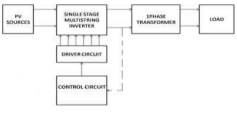
The control strategy of the proposed multistring PV inverter is shown in Fig. 5. This scheme can be easily extended to a higher number of PV strings. Here two ETT PV panels are connected to the single stage multistring inverter. The driver circuit provides the gate signals to the switches in accordance with the control signals from the control circuit and also it isolates the gate signals from power signals. The control circuit provides six digital output control signals for six reverse blocking switches.
Fig. 7 Block diagram
Control circuit generates control signals according to the required output. A single phase 50Hz 12V/230V transformer is connected at the output of proposed multistring inverter to provide single phase 50Hz, 230V AC output. The output of the inve rter is captured to calculate the Total Harmonic Distortion (THD).
B. Switching Algorithm of the Proposed Converter
The operation of the proposed soft-switched multistring inverter consists of several modes in each cycle depending on the number of PV panels connected. The switching flowchart of the converter is shown in Figure 6.Figures 7&8 shows the typical operating modes and link cycle of the proposed PV inverter in the two -string case. The described switching algorithm can be extended to higher number of input solar PV panels.
The entire 50Hz operating cycle can be divided into six modes with time period of 0.0033 seconds each. Total time period of cycle is 0.02 seconds.
A capacitor is connected across the output of the multistring inverter. Due to the existence of the capacitor, the link voltage
'Vc' changes slowly while the switches are turned OFF at the end of each mode. Consequently, the switch voltages change slowly at their turn-off. This provides a soft switching operation to the inverter reducing the switching losses and also functions as a filter.
A single phase two winding transformer is connected to step up the output voltage of multistring inverter to get the required level. The switching sequence of the reverse blocking switches is shown in the figure 6. The switch S31 conducts for first half cycle for the flow of PV panel current in positive direction and switch S3 conducts for the
ISSN(Online): 2319-8753 ISSN (Print): 2347-6710
I
nternational
J
ournal of
I
nnovative
R
esearch in
S
cience,
E
ngineering and
T
echnology
(An ISO 3297: 2007 Certified Organization)
Website: www.ijirset.com Vol. 6, Issue 6, June 2017
Fig8.Control scheme of proposed multistring PV inverter
Fig. 9. Control flow chart
IV. SIMULATION RESULTS
The single stage multistring inverter was simulated using MATLAB/SIMULINK tool. The PV cell was designed and simulated with the help of its equivalent circuit shown in figures 2 & 3. Temperature and irradiation were considered as the changing parameters to change the output of the solar cell. Two PV cells of 12V and 24V were taken as input for the multistri ng configuration as per Figure 4. The switching circuit consists of reverse blocking switches using IGBTs and diodes which are taken from Simulink library. A two winding 12V/230V, 50Hz linear transformer is used to connect the inverter to the load side. Resistive load was considered for the simulation and the switching sequence were provided according to the operation described above. A 50Hz, 20V peak voltage waveform was obtained at inverter output. A 50Hz, 320V peak voltage waveform was obtained at secondary of transformer. The simulation diagram of multistring inverter with and without filter is shown in figure 10 and the output waveforms are shown in figure 11.
ISSN(Online): 2319-8753 ISSN (Print): 2347-6710
I
nternational
J
ournal of
I
nnovative
R
esearch in
S
cience,
E
ngineering and
T
echnology
(An ISO 3297: 2007 Certified Organization)
Website: www.ijirset.com Vol. 6, Issue 6, June 2017
Fig. 11 Output voltage waveforms of load and inverter with and without filter
V.CONCLUSION
A single stage soft-switched multistring inverter for PV systems was simulated using MATLAB/SIMULINK tool. This multi-rated source inverter can have an arbitrary number of PV strings and is capable to obtain the maximum possible power of each string independently. The PV strings can be of different electrical parameters and working conditions. Simulated digital gate pulses are provided to the switches by control circuit. A single phase 50Hz transformer is responsible for boosting the voltage to achieve required output level. Small ac capacitors on primary side of the transformer realize soft -switching operation. They also behave as passive snubbers to avoid voltage spikes. The control scheme and the switching algorithm of the proposed inverter were described. The output of inverter is also read to measure the THD using Matlab FFT analysis. THD of the output waveform was reduced to 12.83% using filter circuits.
REFERENCES
[1] H. Keyhani and H. A. Toliyat, ―A soft-switching three-phase ac–ac con-verter with a high-frequency ac link,‖ in Proc. Energy Convers. Congr. Expo., 2012, pp. 1040–1047.
[2] S. B. Kjaer, J. K. Pedersen, and F. Blaabjerg, ―A review of single-phase grid-connected inverters for photovoltaic modules,‖ IEEE Trans. Ind. Appl., vol. 41, no. 5, pp. 1292–1306, Sep./Oct. 2005.
[3] M. Calais, J.Myrzik, T. Spooner, and V. G. Agelidis, ―Inverters for singlephase grid connected photovoltaic systems—An overview,‖ in Proc. IEEE Power Electron. Spec., 2002, vol. 2, pp. 1995–2000.
[4] C. Meza, J. J. Negroni, D. Biel, and F. Guinjoan, ―Energy-balance modeling and discrete control for single-phase grid-connected PV central inverters,‖ IEEE Trans. Ind. Electron., vol. 55, no. 7, pp. 2734–2743, Jul. 2008.
[5] H. Keyhani, H. A. Toliyat, M. H. Todorovic, R. Lai, and R. Datta, ―Isolated soft-switching HFAC-link 3-phase ac–ac converter using a single-phase HF transformer,‖ in Proc. IEEE 38th Annu. Conf. Ind. Electron. Soc., 2012, pp. 512– 517.
[6] I. D. Kim, and G. H. Cho, "New bilateral zero voltage switching AC/AC converter using high frequency partial-resonant link," Industrial Electronics Society, 1990. IECON '90., 16th Annual Conference of IEEE , vol., no., pp.857-862 vol.2, 27-30 Nov 1990.
[8] R. Lai, F, Wang, R. Burgos, Y. Pei, D. Boroyevich, B. Wang, T.A. Lipo, V.D. Immanuel, and K.J. Karimi, "A Systematic Topolo gy Evaluation Methodology for High-Density Three- Phase PWM AC-AC Converters," Power Electronics, IEEE Transactions on , vol.23, no.6, pp.2665-2680, Nov. 2008.
[9] M. Rashid, Power Electronics Handbook - Devices, Circuits, and Applications, 3rd Edition, New York: Elsevier, 2010.
[10] J. Itoh, D. Matsumura, S. Kondo, A. Odaka, and H. Ohguchi" "A novel control strategy for high-frequency AC-link ACIAC direct converter based on virtual converter system," Power Electronics and Applications, 2005 European Conference on , 2005
[11] A. Balakrishnan, H. A. Toliyat, and W. C. Alexander, "Soft switched ac link buck boost converter," Applied Power Electronics Conference and Exposition, 2008, APEC 2008, Twenty-Third Annual IEEE , vol., no., pp.1334-1339, 24-28 Feb. 2008.
[12] S. Jain and V. Agarwal, ―A single-stage grid connected inverter topology for solar PV systems with maximum power point tracking,‖ IEEE Trans. Power Electron., vol. 22, no. 5, pp. 1928–1940, Sep. 2007.
[13] Pandiarajan N, Muthu R (2011) Mathematical modeling of photovoltaic module with Simulink. International Conference on Electrical Energy Systems (ICEES 2011), p 6
[14] Panwar S, Saini RP (2012) Development and simulation photovoltaic model using Matlab/Simulink and its parameter extraction. International conference on computing and control engineering (ICCCE 2012)
[15] Savita Nema RKN, Agnihotri Gayatri (2010) Matlab/Simulink based study of photovoltaic cells/modules/arrays and their experimental verification. Int J Energy Environ 1(3):14
[16] Sudeepika P, Khan GMG (2014) Analysis of mathematical model of PV cell module in Matlab/Simulink environment. Int J Adv Res Electr Electr Instrum Eng 3(3):7
[17] Tu H-LT, Su Y-J (2008) Development of generalized photovoltaic model using MATLAB/SIMULINK. Proc World Congr Eng Comput Sci 2008:6
[18] H. Patel and V. Agarwal, ―Maximum power point tracking scheme for PV systems operating under partially shaded conditions,‖ IEEE Trans. Ind. Electron., vol. 55, no. 4, pp. 1689–1698, Apr. 2008.
[19] A. C. Nanakos, E. C. Tatakis, and N. P. Papanikolaou, ―A weightedefficiency-oriented design methodology of flyback inverter for AC photovoltaic modules,” IEEE Trans. Power Electron., vol. 27, no. 7, pp. 3221–3233, Jul. 2012.
[20] C. Shih-Ming, L. Tsorng-Juu, Y. Lung-Sheng, and C. Jiann-Fuh, ―A boost converter with capacitor multiplier and coupled inductor for AC module applications,‖ IEEE Trans. Ind. Electron., vol. 60, no. 4, pp. 1503–1511,Apr. 2013.
[21] H. Haibing, S. Harb, F. Xiang, Z. Dehua, Z. Qian, Z. J. Shen, and I. Batarseh, ―A three-port flyback for PV microinverter applications with power pulsation decoupling capability,” IEEE Trans. Power Electron.,vol. 27, no. 9, pp. 3953–3964, Sep. 2012.
[22] IEEE transactions on power electronics, vol. 29, NO. 8, AUGUST 2014 3919― Single-Stage Multistring PV Inverter With an Isolated High-Frequency Link and Soft-Switching Operation‖ Hamidreza Keyhani, Student Member, IEEE, and Hamid A. Toliyat, Fellow, IEEE [23] N. A. Rahim and J. Selvaraj, ―Multistring five-level inverter with novel PWM control scheme for PV application,‖ IEEE Trans. Ind. Electron., vol. 57, no. 6, pp. 2111–2123, Jun. 2010.