Intelligent Control Algorithm for Maximum
Power Point Tracking of PV Arrays
Binhan Kanchan Bijaykant1, Shashi Minz 2
P.G. Student, Department of Electrical Engineering, BIT, Sindri, Jharkhand , India1
Assistant Professor, Department of Electrical Engineering, BIT, Sindri, Jharkhand , India2
ABSTRACT: In PV system power available at the output of solar cell keeps on changing with changing irradiation, temperature and load because solar cell exhibits nonlinear V-I characteristic therefore MPP of solar cell varies. Maximum power point tracking therefore plays an important role in optimizing solar energy efficiency. In this paper two intelligent control technique – Fuzzy logic and Artificial Neural Network are use for MPPT of PV array. Fuzzy logic does not need the knowledge of exact model of the system and uses heuristic reasoning based on experience to deal with this nonlinearity of PV arrays. The proposed ANN is trained with PV output current, voltage to estimate the duty cycle of dc-dc boost converter and their by track MPP of PV arrays. A conventional IC algorithm is compared to these intelligent control algorithm on the basis of settling time, efficiency, transient tracking time, steady state oscillation, dynamic behaviour. MATLAB/SIMULINK is use to design three phase grid connected PV system consisting of 100kW PV array, DC-DC boost converter, three phase three level diode clamped inverter along with synchronous reference frame control strategy connected to utility grid via a three phase coupling transformer.
KEYWORDS: PVarray,MPPT (Maximum power point tracking), ANN(Artificial Neural Network), FLC(Fuzzy logic
control),IC (Incremental conductance )algorithm, boost converter ,duty cycle.
I. INTRODUCTION
With the ever increasing demand of energy due to rapid industrialization, development of technologies and raised standard of living of human being has put a lot of pressure on the non-renewable energy resource. To full fill the requirement of the energy demand renewable energy sources must be used along with non renewable energy sources. Solar energy is lavishly available on the earth surface; it is clean, inexhaustible and free to harvest. Solar energy is not reliable source as the output power of photovoltaic cell depends on solar irradiance, temperature and load [1][2]. The photovoltaic panel has an optimal operating voltage and current where the PV panel can produce maximum power called Maximum power point. Due to the nonlinearity of the I-V and P-V characteristic of solar cell, it is difficult to determine analytically the maximum power operating point. MPPT algorithms are adaptive system used to control power electronic device interconnecting a PV panel and a load. It makes the apparent impedance of the load equal to the impedance of PV array so as to transfer maximum power to load.
There many different techniques for maximum power point tracking of photovoltaic (PV) arrays listed in the literature[6][14]. The conventional MPPT method includes perturbation and observation (P&O), incremental conductance (IC), voltage-feedback methods etc. Fuzzy logic controls (FLC), neural network, genetic algorithm are intelligent method. These methods vary in complexity, sensors required, convergence speed, cost, range of effectiveness, implementation hardware and popularity.
controller is an intelligent way of tracking the maximum power point (MPP). Fuzzy Logic (FL) has been used for tracking the MPP of PV modules because it has the advantages of being robust, relatively simple to design and does not require the knowledge of an exact model [3]. Artificial Neural Network (ANN) is an artificial network that mimics the human biological neural networks behaviour. The primary significance of the neural network is the ability of the network to learn from its environments and to improve its performance through learning [5]. PV array current and voltage are the two inputs given to ANN and it computes an optimized duty cycle to track maximum power point
.
In this paper, using MATLAB /SIMULINK a PV array model is used to simulate actual PV arrays behaviour and then a Maximum Power Point tracking method using Fuzzy logic, ANN is proposed in order to control the DC-DC converter. DC-DC converter is followed by voltage source inverter. VSC is controlled in the rotating dq frame to inject a controllable three phase AC current into the Utility grid to achieve unity power factor operation, current is injected in phase with the grid voltage[12][13]. A phase locked loop (PLL) is used to lock on the grid frequency and provide a stable reference synchronization signal for the inverter control system [13]. A grid-connected complete photovoltaic model is generated to simulate the actual life case.Section II presents proposed system configuration, section III presents modelling of PV cell, section IV presents MPPT algorithm. Finally, Section V presents conclusion.
II. PROPOSEDSYSTEMCONFIGURATION
A grid connected PV system consists of a100kW PV array connected to Dc-Dc boost converter which convert 272V DC to 500V DC whose duty cycle is controlled by (ANN/FLC)MPPT controller which extracts maximum power from the PV array. To convert DC to three phase AC a three phase three level VSC is use which convert 500V DC to 260 V AC then it is connected to a 100kVA 260/25kV three phase coupling transformer then it is given to the utility grid.
III.MODELLINGOFPHOTOVOLTAICCELL
A photovoltaic cell is basically a semiconductor diode whose p–n junction is exposed to sunlight to convert it into electricity. PV cell can simply be represented by a single diode model which is a equivalent circuit consisting of a photo current, an antiparallel diode, a parallel and a series resistor.
By applying Kirchhoff Law in fig 2.The current output of PV module given by
I = − × ( ×( × )−1)−( × ) (1)
IPh is the current generated by incident light, I0 is PV saturation current, q=1.6*10-19C, V is voltage across the diode,
k=1.381*10-23 . T is actual temperature of cell, A is ideality factor used in PV technology, Id is diode current, series
resistance Rse and parallel resistance Rp .
Fig:2 Equivalent circuit of PV cell Fig:3 Equivalent circuit models of generalized PV
A PV cell generates very less voltage .A PV module is made up of solar cells connected in series to obtain adequate operating voltage .These PV module are then connected in series shunt combination to obtain a desire output power. An equivalent circuit for all PV cell, module, and array is generalized and expressed in Fig. 2.7. The mathematical equation of generalized model can be described as[9]
= − × ×( / × ×× / )−1 − ∗ / × (2)
If Np denotes cells connected in parallel and Ns denotes number of cells connected in series . It can be shown that Ns=
Np = 1 for a PV cell. Np = 1and Ns: series number of cells for a PV module, and Ns and Np: series-parallel number for a
PV array.
.
Table – I Electrical Parameter Sun Power SRP- 305-WHT Solar Panel
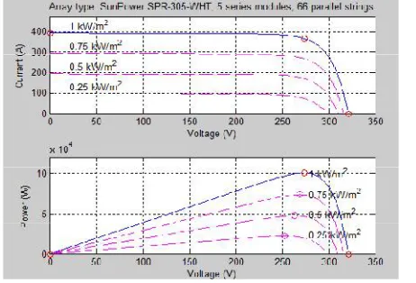
Figure:3 V-I and P-V curve of 100kW PV array
A 100kW PV array is formed by connecting 5 SunPower 305WHT solar panel in series with 66 panel in parallel.fig.3 shows the I-V,P-V curve for 100kW panel with varying irradiation from 0.1kW/m2to 0.25 kW/m2 .
III. MAXIMUM POWER POINT TRACKING
A typical solar panel has low conversion efficiency of 9% to 18% .PV modules also have nonlinear current-voltage (I-V) characteristics that are dependent on solar radiation, temperature and load. Therefore, their operating point that corresponds to the maximum output power varies with the environmental and load conditions as seen in fig.3 Maximum power point tracking technique is used to improve the efficiency of the solar panel. MPPT is a tool for the dynamical optimization of the power produced by a PV array. MPPT is a power electronic device (here boost converter) interconnecting a PV power source and a load. According to Maximum Power Transfer theorem, the power output of a
Maximum power(Pmax) 305W
Voltage at MPP(Vmpp) 54.7V
Current at MPP(Impp) 5.58A
Open circuit voltage(Voc) 64.2
Short circuit current(Isc) 5.96A
Number of cells connected in series
There are different techniques used to track the maximum power point mentioned in literature.[5] Two intelligent MPPT Algorithm based on FLC and ANN are designed and compared to conventional IC algorithm.
A. Ann Based Maximum Power Point Tracking of PV Array
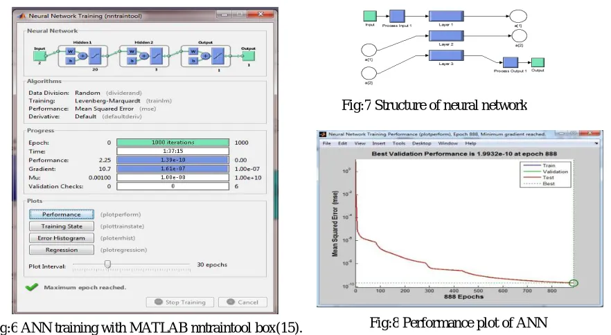
An Artificial Neural Network (ANN) is an information processing paradigm[11]. ANNs are considered nonlinear statistical data modelling tools where the complex relationships between inputs and outputs are modelled. ANN is a massively parallel distributed processing system made up of highly interconnected neural computing elements that have the ability to learn and thereby acquire knowledge and make it available for use. The proposed ANN in this paper is a feed forward neural network comprising four layers namely input layer, 2 hidden layers and the output layer is considered for the online estimation of the duty ratio. The configuration of the proposed four-layer feed forward neural network is illustrated in fig 4.
Collecting Data : In this paper the input data set is PV array output current and output voltage whereas output layer of the proposed ANN comprises is a controlling signal for the boost converter i.e. the duty cycle. Data for duty cycle which is used as the target in the ANN based MPPT is obtained from the Incremental conductance Algorithm with Integral regulator [7]. The training data has been obtained by varying the solar radiation level from 250W/m2 to 1000W/m2. Totally 150000 sets of input data samples are given to the network for training.
Selecting Network Structure : A four layered feed forward network is created using command feedforwardnet. The network is created with two neurons in the input layer, 20 neurons in the first hidden layer, 3 neurons in the second hidden layer and one neuron in the output layer. The input information is connected to the hidden layers through weighted connections and then the output data is calculated. The activation functions used at the input and output layers are tansig and purelin functions respectively
Training the network: The training process determines the connection weights of the neural network. The learning function is taken to be trainlm. “Trainlm” is a network training function that updates weight and bias values according to Levenberg-Marquardt (LM) optimization. The error criterion that is considered for training is Mean Square Error.[05]
=1
2 ( − )
Where p is the index of the output neurons, Opj is the measured output and tpj is the desired output of the output neurons. Fig:5 Simulink model of ANN based MPPT
Fig:4 Four layer feed forward neural network for MPPT of PV array
Fig.6 shows neural network training tool box for training network. Fig.7 shows structure of neural network and fig.8 shows Performance plot of ANN after training network.
The smaller the mean square error is, the better the performance and accuracy the network will achieve in real life
.
fig 8 shows that Best performance is achieved at 1.9932e-10 at 888 epochs.B. Fuzzy Logic Based MPPT
The Fuzzy Logic tool is a mathematical tool for dealing with uncertainty. It refers to a soft computing partnership the important concept of computing with words. Fuzzy logic is tolerant to imprecise data and can model nonlinear functions of arbitrary complexity(9) .The proposed FLC is shown in Fig.10;
It consists of two inputs and one output. The slope of the P-V curve E(K) and the change of slope CE(K) were used as Fig:6 ANN training with MATLAB nntraintool box(15). Fig:8 Performance plot of ANN
Fig:7 Structure of neural network
( ) = ( ) ( ) ( ) ( )
( ) = ( )− ( −1)
1)Fuzzification :
The
fuzzification convert the system actual inputs values error (E) i.e. slope of PV curve and change in error (CE) i.e. change in slope of PV curve and output duty cycle into linguistic fuzzy sets using fuzzy membership function. These variables are expressed in terms of seven linguistic variable negative big (NB), negative medium(NM), negative small(NS), zero(Z), positive small(PS), positive medium(PM), positive big(PB). The triangular membership function is used for simplicity and also to reduce the calculations.Fig:11(a) Membership function of error Fig:11(b) Membership function of change of error
Fig: 11(c) Membership function of duty cycle
2)Rule base & inference engine: Fuzzy rule base is a collection of if-then rules that contain all the information for the controlled parameters. It is set according to professional experience and the operation of the system control(9).
Table: 2 contains 49 control fuzzy rule .These rules are employed for controlling the DC-DC boost converter such as the MPP of the PV Array is reached. E (K) shows if the load operating point at the instant K is located on the left or on the right of the maximum power point on the P-V characteristic where it is equals to zero at MPP as shown in Fig.3 while the change of error CE(K) expresses the moving direction of this point. When E(K) is positive it means that operating point is in left side of the MPP and when it will be negative ,the operating point is in right side of the MPP
Table: II Fuzzy rules
CE
E NB NM NS ZE PS PM PB NB ZE ZE ZE NB NB NB NB
NM ZE ZE ZE NM NM NM NM NS NS ZE ZE NS NS NS NS ZE NM NS ZE ZE ZE PS PM PS PM PS PS PS ZE ZE ZE PM PM PM PM ZE ZE ZE ZE PB PB PB PB ZE PS ZE ZE
(4)
(5)
Case: If E is PB and CE is NB Then ∆ is PB . This implies that if operating point is distant from MPP towards left hand side and the change of slope in P-V characteristic is big in opposite direction, then the duty ratio is largely increased.
Fuzzy inference is the process of mapping from given input to an output. Mapping thus provides a basis from which decision can be made. Here Mamdani’s fuzzy inference method has been used.
3) Defuzzification: The Defuzzification is reverse of the Fuzzification process which converts the set of modified control output values into single point wise values. In this work Centre of Gravity (COG) defuzzification method is used[9].
IV.RESULTSAND DISCUSSIONS
MATLAB SIMULINK software has been to model 100kW PV array with 5 SunPower 305WHT solar panel in series with 66 panels in parallel, MPPT controller based on ANN, FLC, IC algorithm, boost converter, three phase three level VSC and utility grid.
A. Comparison of Maximum Power Point Tracking Technique : Incremental conductance algorithm[4], Fuzzy logic algorithm and Artificial Neural Network based MPPT algorithm are compared on the basis of maximum power extracted from PV array, steady state power ripple, transient tracking time. First the system is operated at nominal operating conditions (25 oC and 1000W/m2).The irradiance is kept constant at 1000W/m2 for 0.7sec then from 0.7 sec to 2 sec irradiation is changed slowly from 1000W/m2 to 250W/m2 and back to 1000W/m2 to 250W/m2 and form 2.3 sec to 2.75 sec a fast changing irradiation from 1000W/m2 to 250W/m2 and back to 1000W/m2 is considered here for simulation.
(a) Comparison of three MPPT algorithms on basis of maximum power extracted from PV array
Fig:13 A Comparative Simulation results showing power extracted from PV Source by using ANN(red) ,FLC(black) and IC(blue) based MPPT algorithm.
Maximum power produced by PV array is 100.7kW from the above fig(3). It is seen that ANN track maximum power of 100.59 kW, FLC extract 100.35kW and IC extract 96.90kW at 1000w/m2 irradiation as seen in fig(13). It also shows that with the change in irradiation from 1000W/m2 to 250W/m2 these three algorithm tracks maximum power. Fig(14)Shows that with the change in irradiation level ANN, FLC, IC algorithm respectively changes it duty cycle to track maximum power.
B. Comparison of three MPPT algorithm on basis of steady state power ripple around MPP of PV array.
Fig:15 A Comparative Simulation results showing steady state power ripple around MPP of PV array by using IC ,FLC and ANN based MPPT algorithm.
At Steady state ,as seen from the fig.15 power ripple at maximum power tracked at 1000W/m2 by ANN (red )is less as compared to FLC(blue) and IC algorithm(green).
C.Comparison of three MPPT algorithm on basis of transient tracking time[8]
.
Transient tracking time required to reach 95% of maximum average power available for extraction at MPP by ANN is 0.082 sec, FLC requires 0.084 sec and IC algorithm takes 0.087sec.
TABLE:IV
Performance comparison of Incremental Conductance, Fuzzy logic and Artificial Neural Network based MPPT algorithms
V. CONCLUSION
It has been observed from above Table IV that ANN based MPPT algorithm is precise in tracking MPP as compared to fuzzy logic and IC based MPPT algorithm. ANN based MPPT shows very good dynamic response under fast and slow changing irradiation and has very small steady state power ripple around maximum power point hence very less energy is wasted at steady state. It is seen from fig.16 that ANN require less settling time and transient tracking time. Efficiency to track MPPT of PV array is highest of ANN algorithm (99.89%) followed by fuzzy logic algorithm (99.65%) then IC algorithm (96.2%).
REFERENCES
[1] Habbati Bellia, Ramdani Youcef ,Moulay Fatima,“A detailed modeling of photovoltaic module using MATLAB” NRIAG Journal of
Astronomy and Geophysics (2014) 3, 53–61.
[2] Huan-Liang Tsai, Ci-Siang Tu, and Yi-Jie Su, Member, IAENG “Development of Generalized Photovoltaic Model Using
MATLAB/SIMULINK “Proceedings of the World Congress on Engineering and Computer Science 2008 WCECS 2008, October 22 - 24, 2008, San Francisco, USA.
[3] F.Bouchafaa, I.Hamzaoui, A.Hadjammar “Fuzzy Logic Control for the tracking of maximum power point of a PV system” F. Bouchafaa et al.
/ Energy Procedia 6 (2011) 633–642
[4] Azadeh Safari and Saad Mekhilef, Member, IEEE “Simulation and Hardware Implementation of Incremental Conductance MPPT With Direct
Parameters MPPT ALGORITHMS
Incremental Conductance
Fuzzy logic Artificial Neural Network
Power(kW) at G=1000W/m2 96.90kW 100.35kW 100.59kW
Voltage at G=1000W/m2 252.10V 267.98V 272.25V
Efficiency 96.2% 99.65% 99.89%
Steady state Power ripple (watts) 93.75-93.71 100.3534-100.3528 100.591-100.695
Transient Tracking Time 0.087s 0.084s 0.082s
Settling time 0.395s 0.3s 0.21s
P_B1(active power) (gridside measurement)
94.26kW 98.65kW 99.01kW
Stability Less stable Stable More stable
Implementation medium Complex complex
PV array dependent no Yes yes
Dynamic response Not good Moderate Very good
[6] Trishan Esram, Patrick L. Chapman “Comparison of Photovoltaic Array Maximum Power Point Tracking Techniques” IEEE Transactions On Energy Conversion, Vol. 22, No. 2, June 2007.
[7] Hemant Kumar, A K Sharma. “Performance Analysis of Maximum Power Point. Tracking Algorithms for Grid Connected PV System”
978-1-4799-6042-2/14/$31.00 ©2014 IEEE
[8] S. Jain and V. Agarwal “Comparison of the performance of maximum power point tracking schemes applied to single-stage grid-connected photovoltaic systems”. IET Electric Power Applications Vol. 1, No. 5, September 2007
[9] Bendib, F. Krim, H. Belmili, M. F. Almi, S. Boulouma “Advanced Fuzzy MPPT Controller for a stand-alone PV system” The International Conference on Technologies and Materials for Renewable Energy, Environment and Sustainability, TMREES14.
[11] Arash Anzalchi and Arif Sarwat. “Artificial Neural Network Based Duty Cycle Estimation for Maximum Power Point Tracking in Photovoltaic Systems” Proceedings of the IEEE SoutheastCon 2015, April 9 - 12, 2015 - Fort Lauderdale, Florida.
[12] Wanchai Subsingha. “Design and Analysis Three Phase Three Level Diode-ClampedGrid Connected Inverter” Energy Procedia 89 ( 2016 )130– 136
[13] Guan-Chyun Hsieh and James C. Hung “Phase-Locked Loop Techniques-A Survey” IEEE Transactions On Industrial Electronics, Vol. 43,No.6, December 1996.
[14] Moacyr Aureliano Gomes de Brito et al “Evaluation of the Main MPPT Techniques for Photovoltaic Applications”IEEE Transactions on Industrial ElectronicsVol. 60, No. 3, March 2013