Seismic Evaluation of RC Unsymmetrical
Building with Floating Columns & Soft storey
Considering Different Configuration
Bhavya B S1, Jisha P2
P.G. Student, Department of Civil Engineering, AWH Engineering College, Calicut, Kerala, India1 Assistant Professor, Department of Civil Engineering, AWH Engineering College, Calicut, Kerala, India2
ABSTRACT:Open first story and Floating columns are typical features in the modern multi-storey constructions in urban India.This paper deals with the study of architectural drawing and the framing drawing of the building having Floating columns & Soft storey. Existing commercial building comprising of G+ 7 structures has been selected for carrying out the project work. The building was modelled as per plan and the plan was remodified in different ways so that total twelve models are carried out in this study.In the present work, the recommendations such as the effect of Infill, Bracings and Shear wall are introduced in the building in order to improve the seismic performance.The structural action of masonry infill panels have been taken into account by modelling them as diagonal struts.Equivalent static and response spectrum methods are used for analysis by ETABS 15.2.0 software. The structure was assumed to be situated in earthquake Zone III & V on a medium soil (type II). The parameters evaluated were displacement, storey drift, storey shear, and storey stiffness of all models are compared and significant co-relationship between these values are established with graphs.
KEYWORDS: Floating column, Soft storey, Infill, Bracings, Shear wall,Equivalent diagonal strut, Equivalent static analysis, Response spectrum analysis, ETABS.
I. INTRODUCTION
Conventional Civil Engineering structures are designed on the basis of strength and stiffness criteria. In case of earthquake forces the demand is for ductility. Larger is the capacity of the structure to deform plastically without collapse, more is the resulting ductility and the energy dissipation. This causes reduction in effective earthquake forces [1].The behaviour of a building during earthquakes depends mainly on its overall shape, size and geometry, in addition to how the earthquake forces are carried to the ground. The earthquake forces developed at different floor levels in a building need to be brought down along the height to the ground by the shortest path; any deviation or discontinuity in this load transfer path results in poor performance of the building. Buildings that have fewer columns or walls in a particular storey or with unusually tall storey tend to damage or collapse which is initiated in that storey [2].
Floating Column:A column is supposed to be a vertical member starting from foundation level and transferring the load to the ground. The term floating column is also a vertical element which ends (due to architectural design/ site situation) at its lower level (termination Level) rests on a beam which is a horizontal member as shown in figure 1.The beams in turn transfer the load to other columns below it. Such columns where the load was considered as point load. This is being provided more space in ground floor for a) Accommodation of parking or ground lobbies b) For architectural beauty c) To increase floor space index [3].
whereas the ‘soft storey’ is severely strained causing its total collapse, much smaller damages occurs in the upper storeys, if at all.
Fig 1: Floating column or Hanging column in a building [4]
When irregular features such as floating columns and soft storey are included in buildings, a considerably higher level of engineering effort is required in the structural design and these kinds of discontinuous members are endangered in seismic regions. But those structures cannot be demolished, rather study can be done to strengthen the structure or some remedial features can be suggested. The stiffness of these columns can be increased by retrofitting or these may be provided with masonry infill, bracing or shear wall to decrease the lateral deformation.
For present study, the building with soft storey &floating columns is provided with Infill, Lateral bracings, Shear wall. Linear analysis was carried out for this study (Equivalent static & Response spectrum) using ETABS 15.2.0.The results were tabulated for lateral displacement, storey drift, storey shear and storey stiffness.
II. RELATEDWORK
A.P. Mundada et al., [5]dealt with the study of architectural drawing and theframing drawing of the building having floating columns. In this study an existingG+7 residential building is selected for the equivalent static analysis of loaddistribution on floating columns and various effects due to it are presented usingstaad pro v8i. Thus the main objective of this paper is to find the variousanalytical properties of the structure and also understand a very systematic andeconomical design of the structure.
Pratyush Malaviya., et al., [6] made a comparative study of effect of floatingcolumns on the cost analysis of a structure designed on staad pro v8i. The conclusion is made thatin the framed structure with no floating columns, the nodal displacements is minimumwith uniform distribution of stresses at all beams and columns and these are the mosteconomical one and at a particular case (all the outer columns(Y direction) in groundfloor) there is maximum requirement of concrete and steel. This type of building isfrequently used so as to avoid any external facility for parking of vehicles; so theanalysis shows that it is not advisable to propose such structures.
Srikanth.M.K et al., [7]studied the importance of explicitly recognizing thepresence of the floating column in the analysis of building and also along withfloating column some complexities were considered for ten storey building atdifferent alternative location and for lower and higher zones.It is concluded that, the displacement of the building increases from lower zones tohigher zones, similarly for drift, because it is correlated with the displacement. Storey shear will bemore for lower floors, then the higher floors due to the reduction in weight.
Prerna Nautiyal et al., [8]investigated the effect of the floating column underearthquake excitation for different soil conditions and a linear dynamic analysis isdone for the 2D frame of the multi-storey building with and without floating columnto achieve the response of the frame for safer and economical design of the structureunder such excitations.
III.OBJECTIVESANDMETHODOLOGY
strut.(d)To carry out Static (ESA) and Dynamic analyses (RSA) for different cases of unsymmetrical building.(e)To compare the multi-storey building with and without floating column, when the floating columns are present at ground floor and different location.(f)To observe the structural performance of the soft storey structure (with and without floating column) having equivalent diagonal strut, bracings, shear wall when subjected to lateral loads.(g)To study the structural response of building in different seismic zones (Zone 3 & Zone 5).(h)To study the structural response of the building models with respect to following aspects –storey displacement, storey shear, storey drift, storey stiffness .Generally these buildings with floating columns are usually designed for gravity loads and are safe under gravity loads but are not designed for earthquake loads. So these buildings are unsafe in seismic prone areas .Hence this study aims to create awareness about these issues in earthquake resistant design of multi-storeyed buildings with floating columns.
Methodology:The methodology worked out to achieve the above-mentioned objectives is as follows:(i) Review the existing literature and Indian design code provision for designing the building.(ii) Select an existing building model for the case study.(iii)The plan is remodified by selecting some of the ground floor columns considered as floating column.(iv) Model the selected BF building with and without floating column.(v) To improve the seismic performance the building with floating column and soft storey is recommending some design recommendations such as infill, bracings and shear wall.(vi) Linear analysis of the building models and a comparative study on the results obtained from the analyses.(vii) Observations of results and discussions.
IV.STRUCTURALMODELLINGANDANALYSIS
One of the major purposes of this work was to test a real life structure under various loads. The building considered is a commercial building having G+7 stories. The original structure is detailed according to new conforming seismic detailing practice as per IS 13920 and Earthquake loads are considered as per IS1893 (part 1):2002.The plan layout for all the building models is same as shown in figure 2.Study has been done on twelve different models of an 8 storey building with special moment resisting frames in two orthogonal directions.
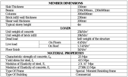
Table 1: Details of Building
MEMBER DIMENSIONS
Slab Thickness 150mm
Beams 230x300mm , 230x600mm
Columns 300x600mm
Brick infill wall thickness 230mm
Shear wall thickness 200mm
Typical storey height 4m
LOADS
Unit weight of concrete 25kN/m3
Unit weight of brick infill 20kN/m3
Dead load Self-weight of the structure
Live load On Floors 4 kN/m
2
On Roof 1.5 kN/m2
Floor finish 1kN/m2
MATERIAL PROPERTIES Characteristic strength of concrete, fck 25 Mpa
Yield stress for steel, fy 415 Mpa
Modulus of Elasticity of steel, Es 2 X 10⁵ Mpa
Modulus of Elasticity of concrete, Ec 27386.13 Mpa
Type Of Frame Special Moment Resisting frame
Diagonal Strut and Model details:The geometric and material properties of the equivalent diagonal strut are required for conventional braced frame analysis to determine the increased stiffness of the infilled frame. The geometric properties are of effective width and the thickness of strut. The infills are modelled by single equivalentdiagonal strut approach and its thickness is equal to infill wall thickness. The ends of strut are pin connected to frame and make it moment releases at it ends, to avoid the transfer of moment from frame to strut.The width of the diagonal strut given as,
W= 0.175(λ'h) -0.4 d' d'= √(L'2+h'2)
Where,
Contact length parameter (λ’) = 4
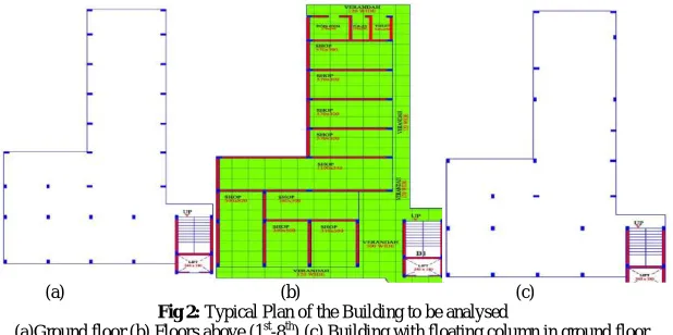
To study the effect of various loads in various Earthquake zone, the building was modelled as per plan and the plan was remodified in different ways and also randomly some of the ground floor columns are considered as floating column as shown in fig 2(c).The discontinuity has been provided at the ground floor only because it has already been observed in previous research studies that floating column caused adverse effects when discontinued at ground floor.In all the models floating columns(5 numbers) are located in ground floor and various features are included in each model in order for earthquake resistant design. The ground floor of the all models were considered as soft storey.
(a) (b) (c)
Fig 2: Typical Plan of the Building to be analysed
(a)Ground floor (b) Floors above (1st-8th) (c) Building with floating column in ground floor
The models are developed by progressive addition of various features. Each model is described in following:
1) MODEL 1: Building model is same as the floor plan, but there is no infill (considered as bare frame) 2) MODEL 2: Building model is same as model 1, with floating columns and soft storey at Ground floor.
3) MODEL 3: Building model is same as model 1, with soft storey at ground floor, has full brick masonry infill in the form of diagonal strut.
4) MODEL 4: Building model is same as model 2, with floating columns and soft storey at Ground floor, has full brick masonry infill in the form of diagonal strut.
5) MODEL 5: Building model is same as model 4, brick masonry infill in the form of diagonal strut provided on the specific corners of outer face of ground floor.
6) MODEL 6: Building model is same as model 4, X – Bracings are provided on the specific corners of outer face.
7) MODEL 7: Building model is same as model 4, Shear wall is provided on the specific corners of outer face 8) MODEL 8: Building model is same as model 4, brick masonry infill in the form of diagonal strut provided on
the location of floating columns
11) MODEL 11: Building model is same as model 1, located in ZONE V. 12) MODEL 12: Building model is same as model 2, located in ZONE V.
The configuration of infill, bracings and shear wall for (Model 5 to model 10) are shown in figure 3.For model 5, model 6, model 7, infill bracings and shear wall provided on all possible corners as shown in figure while for model 8, model 9, model 10, they are provided on the floating column locations as shown in figurebelow:
(a) (b)
Fig 3: Configuration of building models (a)Building Model 5,6,7 (b) Building Model 8,9,10
V. RESULTSANDDISCUSIONS
Equivalent static analysis (ESA) and Response spectrum analysis (RSA) has been performed for each model in ETABS 15.2.0 software. From the obtained results below charts has been drawn in X direction. Similar variation is observed on Y direction.
4.1. Lateral Displacement
The lateral displacement profiles of the variousmodels for the ESA and RSA performed in this study are shown inFigures below:
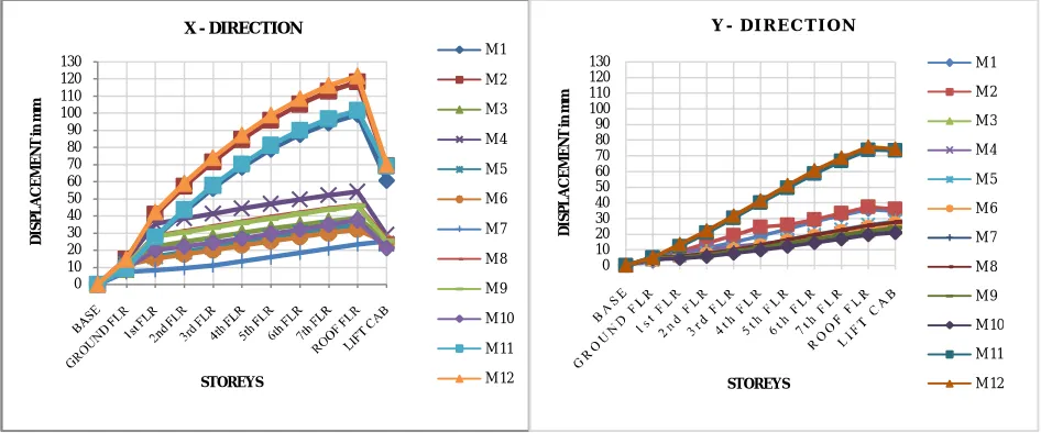
Fig 4: Comparison of Displacement in X & Y direction due to lateral loads in ESA
0 10 20 30 40 50 60 70 80 90 100 110 120 130
D
IS
P
L
A
C
E
M
E
N
T
in
m
m
STOREYS
X - DIRECTION
M 1 M 2 M 3 M 4 M 5 M 6 M 7 M 8 M 9 M 10 M 11 M 12
0 10 20 30 40 50 60 70 80 90 100 110 120 130
D
IS
P
L
A
C
E
M
E
N
T
in
m
m
STOREYS
Y - D I R E C T I O N
Storey displacement is the lateral movement of the structure caused by lateralforce. The deflected shape of a structure is most important and most clearly visiblepoint of comparison for any structure. The maximum displacements of building in different stories in both X and Ydirections for all models have been compared. No other parameter of comparison can give a better idea of behavior of the structure than comparison of storey displacement.
Fig 5: Comparison of Displacement in X & Y direction due to lateral loads in RSA
4.2.Storey Drift
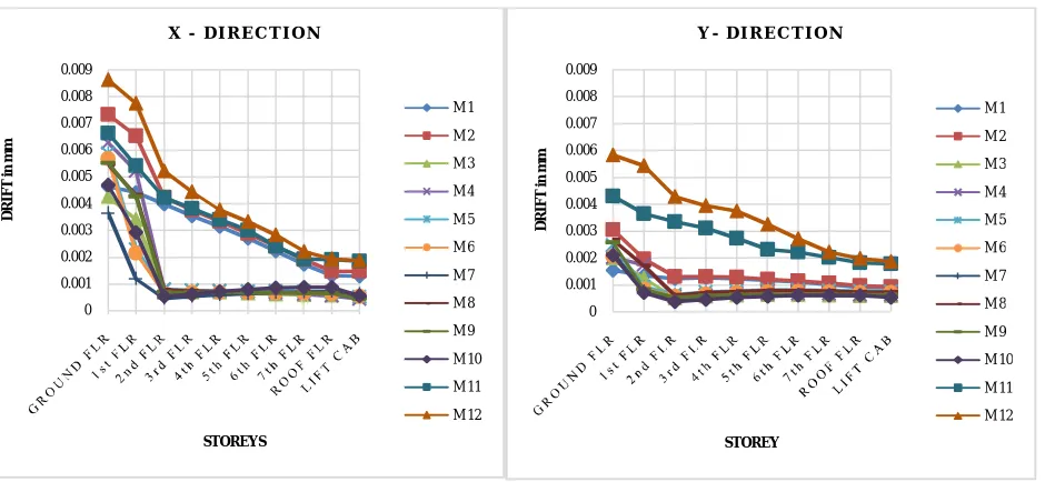
Fig 6:Comparison of Storey Drift in X & Y direction of the different models in ESA
Story drift is the displacement of one level relative to the other level above orbelow. Damage to non-structural components of buildings depends on drift. First of all consider model 1 “Bare Frame (G+7)” because, it is a basic or
0 10 20 30 40 50 60 70 80 90 100 110 120 130 D IS P L A C E M E N T in m m STOREYS
X - D I R E C T I O N
M 1 M 2 M 3 M 4 M 5 M 6 M 7 M 8 M 9 M 10 M 11 M 12 0 10 20 30 40 50 60 70 80 90 100 110 120 130 D IS P L A C E M E N T in m m STOREYS
Y - D I R E C T I O N
M 1 M 2 M 3 M 4 M 5 M 6 M 7 M 8 M 9 M 10 M 11 M 12 0 0.001 0.002 0.003 0.004 0.005 0.006 0.007 0.008 0.009 D R IF T i n m m STOREYS
X - D I R E C T I O N
M 1 M 2 M 3 M 4 M 5 M 6 M 7 M 8 M 9 M 10 M 11 M 12 0 0.001 0.002 0.003 0.004 0.005 0.006 0.007 0.008 0.009 D R IF T i n m m STOREY
Y - D I R E C T I O N
traditional structure in which no other element are included or considered in structure for improving the performance of the building, so the results of the Bare frame (G+7) can compare with the results of the other models. The storey drifts at each floor height of the model 1 (i.e. Bare Frame (G+7)) with all load combination get from software, from this result understand the load combination shows the maximum storey drift. So here storey drift of that maximum load combinations in all models can considered as a benchmark to state the comparative statement.
Fig 7:Comparison of Storey Drift in X & Y direction of the different models in RSA
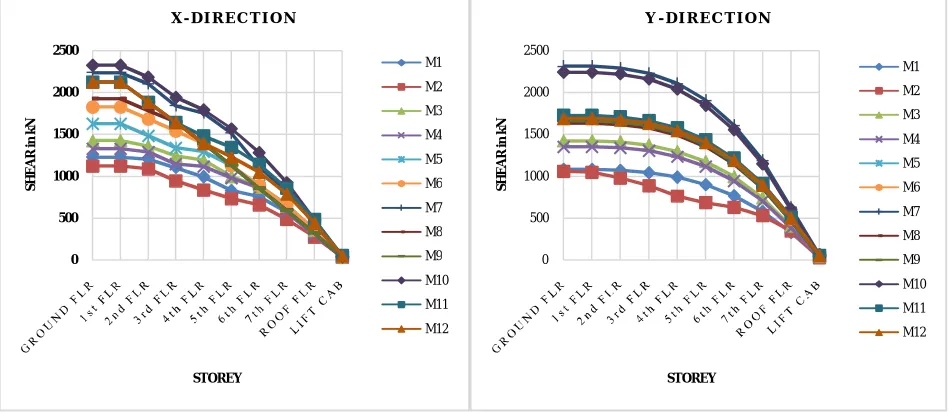
4.3. Storey Shear
Storey shear is the distribution of design base shear along height of thestructure. Storey shear depends on stiffness in the frame. The infill as equivalentdiagonal strut have significance influence on shear. The struts resist the lateral seismicforces through axial compression along the strut. Shear induced at the base of building during earthquake is called base shearwhich depends on the seismic mass and stiffness of building.
Fig 8:Comparison of Storey shear of all models in X &Y direction in ESA
0 0.001 0.002 0.003 0.004 0.005 0.006 0.007 D R IF T i n m m STOREY
X - D I R E C T I O N
M 1 M 2 M 3 M 4 M 5 M 6 M 7 M 8 M 9 M 10 M 11 M 12 0 0.0005 0.001 0.0015 0.002 0.0025 0.003 0.0035 D R IF T i n m m STOREY
Y - D I R E C T I O N
M 1 M 2 M 3 M 4 M 5 M 6 M 7 M 8 M 9 M 10 M 11 M 12 0 500 1000 1500 2000 2500 S H E A R i n k N STOREY
X - D I R E C T I O N
M1 M2 M3 M4 M5 M6 M7 M8 M9 M10 M11 M12 0 500 1000 1500 2000 2500 S H E A R i n k N STOREY
Y - D I R E C T I O N
Storey shear is minimum forbare frame models as the mass is less, and shear is maximumfor building with shear wall The shear increase also by theintroduction of infill and bracings too. Due to the introduction of floating columns in the buildingthe value of shear decreases due to increase of natural period of vibration of structure.Also, the mass of concrete in column is less for floating column building as comparedto normal building (NB), so this further decreases the base shear.
Fig 9:Comparison of Storey shear of all models in X &Y direction in RSA
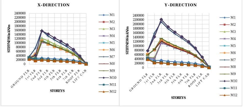
4.4. Storey Stiffness
The storey stiffness is defined as the magnitude of the force couple required atthe floor levels adjoining the storey to produce a unit lateral translation within thestorey, letting all the other floors to move freely. The stiffness of twelve models in X& Y directions for both analysis are shown in figures below:
Fig 10: Comparison of Storey Stiffness in X & Y direction of different models in ESA
0 500 1000 1500 2000 2500 S H E A R i n k N STOREYS
X - D I R E C T I O N
M 1 M 2 M 3 M 4 M 5 M 6 M 7 M 8 M 9 M 10 M 11 M 12 0 500 1000 1500 2000 2500 S H E A R i n k N STOREY
S T O R E Y S H E A R : Y - D I R E C T I O N
M 1 M 2 M 3 M 4 M 5 M 6 M 7 M 8 M 9 M 10 M 11 M 12 0 200000 400000 600000 800000 1000000 1200000 1400000 1600000 1800000 2000000 2200000 2400000 S T IF F N E S S i n k N /m STOREYS
X - D I R E C T I O N
M 1 M 2 M 3 M 4 M 5 M 6 M 7 M 8 M 9 M 10 M 11 M 12 0 200000 400000 600000 800000 1000000 1200000 1400000 1600000 1800000 2000000 2200000 2400000 S T IF F N E S S i n k N /m STOREYS
Y - D I R E C T I O N
Except BF models all other models shows a reduction in the stiffnessvalues in ground and first floor after that it reach a particular value from second floorand gradually decreases. This is due to the presence of floating column and soft storeyin ground floor. The BF models shows a constant variation in stiffness. For the building models at hand, the storey stiffness of the first and secondstoreys are comparatively less compared to other storeys except bare frame buildingmodels. The stiffness irregularity in building models with soft first storey is evidentthat they are weak storeys. Here, stiffness is more for building having shear wallconfigurations.
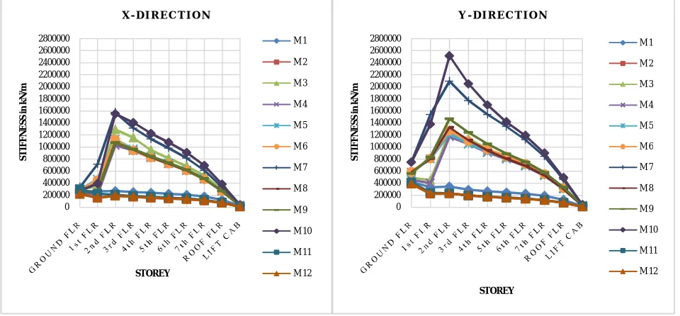
Fig 11: Comparison of Storey Stiffness in X & Y direction of different models in RSA
VI. CONCLUSION
Following conclusions have been made on the basis of analysis and results: 1. Floating column building shows poor performance during earthquake.
2. RC frame buildings with open first storeys are known to perform poorly during instrong earthquake shaking. The drift and the strength demands in the first storeycolumns are very large for buildings with soft ground storeys. It is not very easy toprovide such capacities in the columns of the first storey. Thus, it is clear that suchbuildings will exhibit poor performance during a strong shaking. This hazardousfeature of Indian RC frame buildings needs to be recognized immediately, andnecessary measures taken to improve the performance of the building.
3. The displacement of building increases from lower zones to higher zones, because the magnitude of intensity will be more for higher zones, similarly for drift, because it is correlated with the displacement. In all models the displacement values are less for lower zones and it goes on increases for higher zones in ESA and RSA methods. 4. The storey displacements increase when floating columns are introduced in the building, which proves that
buildings with floating columns in ground floor are more vulnerable during earthquake. It was also observed that deflections increase marginally in that storey where floating columns are located.
5. Out of all the models, by using ESA & RSA methods to evaluate storey drift, multi-storey building with shear walls has performed exceedingly well when compared with normal multi-storey building, building with bracings and masonry infill walls. Drift is more severe in ground floor due to vertical irregularity
6. Storey shear reduces due to presence of floating column in building as the mass isless for building with floating column. Storey shear will be more for lower floors than the higher floors due to the reduction in weight when we go from bottom totop floors. And with this if we reduce the stiffness of upper floors automaticallythere will be a reduction in weight on those floors so in the top floors the storeyshear will be less compared to bottom stories.
0 200000 400000 600000 800000 1000000 1200000 1400000 1600000 1800000 2000000 2200000 2400000 2600000 2800000
S
T
IF
F
N
E
S
S
i
n
k
N
/m
STOREY
X - D I R E C T I O N
M 1 M 2 M 3 M 4 M 5 M 6 M 7 M 8 M 9 M 10 M 11 M 12
0 200000 400000 600000 800000 1000000 1200000 1400000 1600000 1800000 2000000 2200000 2400000 2600000 2800000
S
T
IF
F
N
E
S
S
i
n
k
N
/m
STOREY
Y - D I R E C T I O N
7. The building with shear wall configuration shows more stiffness compared toother models. Nevertheless building with masonry infill as equivalent diagonal strut, bracings also shows good performance. Except BF models all other modelsshows a reduction in the stiffness values in ground and first floor after that it reachsecond floor and gradually decreases. This is due to the presence of floatingcolumn and soft storey in ground floor. The BF models shows a constant variationin stiffness.
8. The recommendations such as shear walls, infill walls, bracings are considered inthe modelling and analysis and observed that they can also be designed as anearthquake resistant up to an extent, such that on introduction of floating columnsin the RC frames increases the time period of bare frames due to decrease in thestiffness.
9. On comparison of the results obtained for each model, it is observed that thebuilding with shear wall are much preferable when compared with otherrecommendations.
Though floating columns are of more interest to architects for construction of multi-storey buildings in urban areas which are not as reliable as the conventional structures. The failure of storeys having floating columns can have a serious effect on progressive collapse of the building. Hence, floating columns should be avoided as faras possible in seismic regions and if they are unavoidable, then the structure should bestrengthened by adopting some remedial features such as infill, bracings and shearwall etc. The analysis also proves that irregularities are harmful for the structures and itis important to have simpler and regular shapes of frames as well as uniform loaddistribution around the building especially in seismic zone areas. Therefore, as far aspossible irregularities in a building must be avoided. But, if irregularities have to beintroduced for any reason, they must be designed properly following the conditions ofIS 1893-part-1: 2002 and IS-456: 2000, and joints should be made ductile as per IS 13920:1993. Now a days, complex shaped buildings are getting popular, but theycarry a risk of sustaining damages during earthquakes. Therefore, such buildingsshould be designed properly taking care of their dynamic behaviour.
VII. SCOPEFORFUTUREWORK
1. The applicability of the procedure of taller structure and structure with large time periods needs to be investigated. 2. In this work column size has been kept constant throughout the building height. One may go for the variation of sizes
for the different levels as per the actualdesign consideration. 3. Nonlinear analysis need to be carried out for all the models.
4. The reactions at footing level is to be investigated and modified for the presentstudy
5. An experimental investigation and verification can be done with small scalemodel on a shake table under simulated motions.
6.Design and estimation of building is necessary for checking the cost effectivenessof these measures used for improving the seismic performance of structure.
REFERENCES
[1] Sabari S, Mr.Praveen J.V, (2015), “Seismic Analysis of Multistorey Buildingwith Floating Column”, International Journal of Civil and Structural Engineering
Research ISSN 2348-7607, Vol. 2, Issue 2, pp: (12-23).
[2] T.Raja Sekhar, Mr.P V Prasad, (2014), “Study Of Behaviour Of Seismic Analysis Of Multi Storied Building With And Without Floating Column”, Caribbean
Journal of Science and Technology, Vol2, 697-710.
[3] Prof. Sarita Singla, Er. Ashlie Rahman, (2015), “Effect of Floating Columns on Seismic Response of Multi-Storeyed RC Framed Buildings”, International Journal
of Engineering Research & Technology (IJERT), ISSN: 2278-0181, Vol. 4 Issue 06.
[4] Isha Rohilla, S.M. Gupta, Babita Saini, (2015), “Seismic Response Of Multi-Storey Irregular Building With Floating Column”, International Journal of Research
in Engineering and Technology, Volume 04, Issue 03.
[5] A.P. Mundada, and S.G. Sawdatkar, (2014), “Comparative Seismic Analysis of Multistorey Building with and without Floating Column”, International Journal of
Current Engineering and Technology, E-ISSN 2277 – 4106, P-ISSN 2347 – 5161.
[6] Pratyush Malaviya, Saurav,(2014), “Comparitive Study of Effect of Floating Columns on the Cost Analysis of a Structure Designed On Stadd Pro V8i.”
International Journal of Scientific & Engineering Research, Volume 5, Issue 5, 22 ISSN 2229-5518.
[7] Srikanth.M.K, Yogeendri.R.Holebagilu, (2014), “Seismic Response of Complex Buildings with Floating Column for Zone II and Zone V”, International journal of
Engineering Research-Online, Vol.2. Issue.4, ISSN: 2321-7758.
[8] Prerna Nautiyal , Akhtar Saleem, Batham Geeta,(2014),“Seismic Response Evaluation of RC frame building with Floating Column considering different Soil
Condition”, International Journal of Current Engineering and Technology”, Vol.4, pp. 132-138.
[9] SukumarBehera, (2012), “Seismic Analysis of Multistory Building with Floating Column” A Thesis of National Institute Of Technology Rourkela, Pp. 21-93.
![Fig 1: Floating column or Hanging column in a building [4]](https://thumb-us.123doks.com/thumbv2/123dok_us/1630801.1203283/2.595.175.416.214.315/fig-floating-column-hanging-column-building.webp)