Design and Analysis Characterization of Car
Bumper Using Glass Fiber Reinforced With
Aluminium
G.Annamalai 1, V.Thirumalairaj 2, R.Santhaseelan3, M.Pradeep4, R.Nagaraja5
Lecturer, Department of Mechanical Engineering, AMK Polytechnic College, Chembarambakkam, Chennai, Tamil Nadu, India1
Assistant Professor, Department of Mechanical Engineering, Nadar Saraswathi College of Engineering and Technology, Theni, Tamil Nadu, India2,
Assistant Professor, Department of Mechanical Engineering, Nadar Saraswathi College of Engineering and Technology, Theni, Tamil Nadu, India3
Assistant Professor, Department of Mechanical Engineering, Nadar Saraswathi College of Engineering and Technology, Theni, Tamil Nadu, India4
Assistant Professor, Department of Mechanical Engineering, Nadar Saraswathi College of Engineering and Technology, Theni, Tamil Nadu, India5
ABSTRACT: Fiber metal laminates are good candidates for advanced aerospace structural applications due to their high specific mechanical properties especially fatigue resistance. The most important factor in manufacturing of these laminates is the adhesive bonding between aluminium and FRP layers. In this study several glass-fiber reinforced aluminium laminates with different bonding adhesion were manufactured. Mechanical Tests like Tensile, Compression and Impact tests were carried out based on ASTM standard were then conducted to study the effects of interfacial adhesive bonding on impact behaviour of these laminates. It was observed that the damage size is greater in laminates with poor interfacial adhesion compared to that of laminates with strong adhesion between aluminium and glass layers. In addition, FMLs of with good adhesion bonding show better resistance under low velocity impact and their corresponding contact forces are about 25% higher than that of specimens with a weak bonding. Moreover, maximum central deflections in laminates with strong bonding are about 30% lower than that of FMLs with poor adhesion.
KEYWORDS:Adhesive bonding, FRP layers, ASTM, FMLs with poor adhesion. I. INTRODUCTION
Basic requirements for the better performance efficiency of an aircraft are high strength, high stiffness and low weight. The conventional materials such as metals and alloys could satisfy these requirements only to a certain extent[1]. This lead to the need for developing new materials that can whose properties were superior to conventional metals and alloys, were developed. [2]
A composite is a structural material which consists of two or more constituents combined at a macroscopic level.[3] The constituents of a composite material are a continuous phase called matrix and a discontinuous phase called reinforcement.[4]
boron, glass etc[5]. Low cost, high strength and simple manufacturing principles are the reason why they are most commonly used in the repair of aircraft structures.[6]
To measure the relative mechanical advantage of composites, two parameters are widely used, namely, the specific modulus and the specific strength. These two parameter ratios are high in composites.[7]
In the highly competitive airline market, using composites is more efficient.[8] Though the material cost may be higher, the reduction in the number of parts in an assembly and the savings in the fuel cost makes more profit.[9] It also lowers the overall mass of the aircraft without reducing the strength and stiffness of its components.
Fig1.1 Primary Material Selection Parameter For A Hypothetical Situation For Metal And Composite
II.LITERATURE REVIEW
S.Prabhakaran (2012) et al performed the fabrication on composite bumper for light passenger vehicles glass / epoxy with single ratio of composites. Here the bumper is fabricated and impact test is carried at a velocity of 2.22 m/s [1].
Celal Erci and Mofit Gulgec (2012) perform an Experimental Investigation on the impact response of composite materials by means of using drop weight testing machine at different energy levels. The materials used are Unidirectional E-glass fibre, Woven E-glass fibre and Woven Aramid fibre [2]. Mehmet Aktas et al (2009) studied the impact response of unidirectional glass/epoxy laminates by considering energy profile diagrams and associated load– deflection curves. Damage modes and the damage process of laminates under varied impact energies were discussed. Two different stacking sequences, [0/90/0/90]s and [0/90/+45/−45]s, were chosen in tests for comparison [3]. Amal A.M.Badway (2012) performed the impact behaviour on glass fibres reinforced composites at different temperatures. The fabrication was carried on unidirectional laminate of glass fibre as a reinforcement and polyester resin as a matrix by hand layup method. The fibres are oriented in two sequences of 0° / 45° / 90° and 0° / 90° / 0° and fibre volume fraction of 16 %, 23% and 34.9% are different and it is tested at different temperatures on izod impact test. It shows that the increase in fibre volume fraction shows the increase in impact strength [4].
III.CLASSIFICATION OF COMPOSITE
Composites are classified by
1. the geometry of the reinforcement as particulate, structural and fibers 2. the type of matrix as polymer, metal and ceramic
3. Composites can be categorized into three groups on the basis of matrix material. They are: * Metal Matrix Composites (MMC)
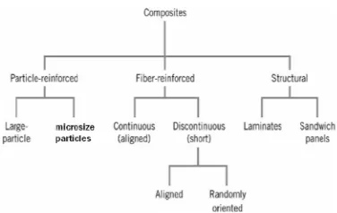
3.1. CLASSIFICATION OF POLYMER COMPOSITES
Fig 1.2. CLASSIFICATION OF POLYMER COMPOSITES
3.2. FIBER REINFORCED POLYMER ( FRP )
The fiber reinforced composites are composed of fibers and a matrix. Fibers are the reinforcing elements and the main source of strength while matrix glues all the fibers together in shape and transfers stresses between the reinforcing fibers. Sometimes, filler is added to smoothen the manufacturing process and to impact special properties to the composite’s .These also reduces the production cost. Most commonly used agents include asbestos, carbon/graphite fibers, beryllium, beryllium carbide, beryllium oxide, molybdenum, aluminum oxide, glass fibers, polyamide, natural fibers etc. Similarly common matrix materials include epoxy, phenolic resin, polyester, polyurethane, vinyl ester etc. Among these materials, resin and polyester are most widely used. Epoxy, which has higher adhesion and less shrinkage than polyesters, comes in second for its high cost.
Fig 1.3 Types Of Fibber Reinforced Polymer
3.3.FIBER SYSTEM CODES.
S.NO CODE FIBER
1 AIO Alumina 2 Ar Aramid 3 B Boron 4 C Carbon 5 GI Glass 6 DGI D-Glass 7 EGI E-Glass 8 GR Graphite 9 Li Lithium
IV. CRACK FAILURE IN GLASS FIBERS
Most of the modern car bumpers made up of glass fiber. For the main purpose of light weight, high strength and good aesthetic look. But when small accident happened the glass fibered car bumpers will cracked. For example a dog hits by a car. The reason for crack penetration is one layer material and also low ductile property of Glass Fiber. Glass Fiber is reinforced with Aluminium alloy, where asAluminium has good ductile property may solve the problem.
Figure 6.1Crack Failure
V. LAMINATE PREPARATION
METHOD: HAND LAY-UP
Even though the method has been replaced with automated techniques, the lay-up of preimpregnated material by hand is the oldest and most common fabrication method for advanced composite structures. Furthermore, the basic features of the method remain unchanged. Each step must follow in successive fashion in order to obtain a high-quality composite laminate after final processing. A description of these steps follows.
Figure5.1 Laminate Preparation
VI.SIMULATION AND RESULTS
6.1 MODELING
new designs or concepts on the computer gives the opportunity to eliminate problems before beginning production. Additionally, designers can quickly and easily determine the sensitivity of specific molding Parameters on the quality and production of the final part.
The car bumper model is created by modeling software like pro-E, Catia and it is imported in to the analysis software and the loading, boundary conditions are given to the imported model and result are evaluated by post processor. The different comparative results of glass fiber car bumper and glass reinforced with aluminium car bumper are obtained to predict the advantages of car bumper for a vehicle.FEA tool is the mathematical idealization of real system. Is a computer based method that breaks geometry into element and link a series of equation to each, which are then solved simultaneously to evaluate the behavior of the entire system. It is useful for problem with complicated geometry, loading, and material properties where exact analytical solution are difficult to obtain. Most often used for structural, thermal, fluid analysis, but widely applicable for other type of analysis and simulation.
DIMENTIONS
LENGTH = 250mm THICKNESS = 4.0mm WIDTH = 25mm
Figure 6.1Modeling of Car Bumper
6.2 MESHING
Meshing involves division of the entire of model into small pieces called elements. This is done by meshing. It is convenient to select the free mesh because the car bumper has sharp curves, so that shape of the object will not alter. To mesh the car bumper the element type must be decided first. Here, the element type is solid 72. Fine mesh is created with 16916 nodes and 2212 elements. The material properties of the given Car Bumper are given in table 1 and table 2.
Fig 6.2Meshing of Car Bumper
Table 6.1: Properties Of Aluminium
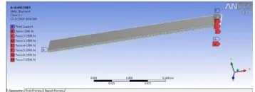
6.3 BOUNDARY CONDITIONS
The Car Bumper is mounted on the front part of chassis of the automobile; the frame of the vehicle is connected to the ends of the Car Bumper. The ends of the Car Bumper are formed in the shape of rectangle.. The load is applied along Fy direction. Same procedure is conducted for composite Car Bumper..
Figure 6.3Boundary Conditions of Car Bumper
6.4 STATIC ANALYSIS
Figure 6.4Static Analysis of Pure glass Figure 6.5Static Analysis of Glass Fiber with Aluminium
6.5 IMPACT ANALYSIS
Figure 6.6Impact Analysis of Glass fiber Figure 6.7Impact Analysis of Glass fibber withAluminium
6.6 LIFE DATA ANALYSIS
:
This is carried out by applying a load of 1000N and the analysis is carried out by the above mentioned four approaches. Goodman’s and Gerber’s approach: Using the Gerber’s theory the life data obtained is similar to the Goodman’s theory.
Table 3.3 Total Deformation
VII REVIEW ON TENSILE TEST
This test is of static type i.e. the load is increased comparatively slowly from zero to a certain value.Standard specimens are used for the tension test. There are two types of standard specimen are which are generally used for this purpose, which have been shown below:
Specimen I& II:
Figure7.1 Specimen
Figure 7.2stress strain curve
Elastic Action:
The elastic is an adjective meaning capable of recovering size and shape after deformation. Elastic range is the range of stress below the elastic limit
.
Figure 7.3 Elastic Action Curve
Figure7.4 Stress Strain Curve For Iron Or Steels With High Carbon Contents
VIII. GRAPHS AND TEST RESULT
8.1 GFRP-Al RESULT
8.2.1 TENSILE TEST
Specimen 1
8.3 LOAD VS DISPLACEMENT
Figure8.1. Load VS Displacement and Stress VS Strain
IX. FUTURE SCOPE
In this regard the laminate will prepare according to study the thermal characterization and mechanical characterization. FMLs consist of metallic alloy and fibre reinforced prepreg. Mostly commercially avaible GLARE, ARALL and
CARALL consist various aluminium alloys. Many researches have been trying to use possible metallic alloys such as magnesium, titanium, etc. instead of aluminium alloys. It is expected that this diversity gives optimum mechanical properties.Same efforts have been examined for engineering polymeric materials to replace fibre reinforced prepreg.
X. CONCLUSION
From the obtained result we find that the tensile and impact strength of the glass fiber with Al is higher than the glass fiber alone. This will effect in the application like automobile, aeronautical and marine structures.
This result will produce the more fusible and dynamic properties in the composite structure. The strength of the glass fiber with al is more than the glass fiber laminate.
In the flexural strength of will not be increased during the reinforced the al with glass fiber ,but during the testing the glass fiber with al specimen was not broken which cause the bending only.so that the elastic property will be high when compared to that of glass fiber alone.
After releasing the load the glass fiber al specimen’s was tried to regain to original level, which will increase the elastic property of the laminate.
Also conclude that, even when increases the strength also will not effect on the actual weight and cost of the laminate since that al is lighter and cheaper.
REFERENCES
[1]H.S.Park,X.P.Dang, A.Roderburg, “Development of Plastic Front Panels Of Green Cars” CIRPJournal of Manufacturing &Technologyvol 26 Pages 35-53,1998
[2]Kuziak.R.Kawalla,R.waengler.s. “Advanced high strength materials for automotiveindustry A review” Journal of Archives of Civil & Mechanical engineering .volume 8 issue2, 2008-12-30 ,Pages 103-117,1998
[3]Falaichen, Bert Juttler,“Geometric Modeling & Processing”, Journal on CAD, volume 42 issue1 pages1-15,1996
[4]David H. Allen “Structural Analysis, Aerospace” Journal on Encyclopedia of Physical science and technology 3rd edition 2003
[5]Japan.s.Daniel.L. and Theodor .k.2005. “Finite Element Analysis of Beams”, Journal of Impact engg.Vol31, Pages 861-876., Pages155-173,1999. [6]OLBISIolagoke “Hand book of Thermo Plastics”, MarcelDekker, New York. Pages 102-108,1997
[8]Dominick v. rosato, “Plastics Engineering”, Manufacturing & Data Hand Book. Pages 102-108,1997 [9]Donald v.rosato, “Plastics Engineering”,Manufacturing& Data Hand Book .Pages216-222,1992
0 1 2 3 4 5 6 7 8 9 10111213141516
Lo
a
d
N
Displacement mm
Load Vs Displacement
0 13 26 39 52 65 78 91 104 117 130
St re ss N /m m 2 Strain %