Predicting Axial Shortening of Vertical
Elements in High Rise Buildings by Using
PCA Method
Diptesh Patil1, M. N. Bajad2
P.G. Student, Department of Civil Engineering, Sinhgad College of Engineering, Pune, Maharashtra, India1
Associate Professor, Department of Civil Engineering, Sinhgad College of Engineering, Pune, Maharashtra, India2
ABSTRACT: Tall concrete buildings experience time-dependent axial shortening which may be interpreted as either absolute or differential, the former being with respect to a single column or core element, the latter being with respect to adjacent elements.The effects of column shortening, both elastic and inelastic, take on added significance and need special consideration in design and construction with increased height of structures. Calculation of exact values of axial shortening is not a straight forward task since it depends on a number of parameters such as the type of concrete, reinforcement ratio, and the rate and sequence of construction. All these parameters may or may not be available to the design engineer at the preliminary design stage of construction. Furthermore, long term shortening of columns could affect the horizontal structural members such as beams and floors and hence could affect the finishes and partitions. Therefore, a reasonable idea about the probable axial shortening could be important for construction engineers and project managers as well.This paper does a study ofcolumn shortening by using PCA(Portland Cement Association) method.In order to analytically solve the problem, the construction stage analysis function of MIDAS Gen considering shrinkage and creep effect is applied on a G+40-storey RC frame structure with internal core wall.
KEYWORDS: Column shortening, Construction stage analysis, Creep, Deformation, High rise buildings, Shrinkage.
I. INTRODUCTION
In tall buildings, vertical structural members such as columns and core walls arecontinuously subjected to a certain amount of vertical movement or axial shortening.For steel structures, axial shortening is rather fundamental as steel columns onlyundergo elastic shortening at the instance of load application. However, in the case ofreinforced concrete columns and core walls, the focus of this paper, the phenomenonbecomes more complicated as the columns also undergo long-term shortening due tocreep and shrinkage.According to Fintel and Ghosh (1984), axial shortening in concrete buildings isdefined as the combined shortening due to elastic, shrinkage and creep effects of acolumn and can be as high as 1 inch for every 80 feet of building height.
Combination of axial creep, shrinkage and elastic shortenings causes axial shortening. In high rise buildings, perimeter columns tend to be more heavily stressed compared to shear walls of internal core. These perimeter columns thereby tend to deform axially at higher rates compared to the shear walls. This leads to differential axial shortening (DAS) between the columns and shear walls. DAS increases with building height and non-vertical load path as a result of geometric complexity of structural framing systems and causes serviceability related problems; impacting on floor flatness, load redistribution and cracking.
Therefore to mitigate above effects column shortening needs to be investigated.
In this paper column deformation is predicted by defining time dependent material properties i.e creep and shrinkage using PCA method. This research can be applied in designing of high rise buildings where considering column shortening at design stage and suggesting compensation for this column shortening will increase the safety and serviceability limit state of building structure. Ultimately future cost for repairing and retrofitting of damaged structural components can be reduced. Also analysing structure by construction stage analysis more accurate results about load distribution can be obtained
II. LITERATUREREVIEW
Fintel, M., and Khan, F. R. (1969) [1] outlined a procedure for prediction of the amount of creep and shrinkage strains. Consideration is given to the loading history of columns in multi-storey buildings, which receive their load in as many in-remints as there are stories in the building, thus considerably reducing the creep as compared to a single load application. Also, volume-to-surface ratio of sections and the effect of reinforcement on the creep and shrinkage is considered.
S.C.Chakrabarti , et al. (1978) [2] observed that simulation of sequence of construction in the analysis leads to considerable variations in the design moments obtained by conventional one step analysis. It is, therefore, necessary that for multi-storied building frame, the effect be taken into consideration. Although exact simulation of the construction sequence may be difficult, idealization of the sequence of construction on the basis of a simplified model is always possible and some approximate ratios of sequential analysis and one step analysis depending upon relative beam and column stiffness are desirable as a design load.
Mark Fintel, et al. (1987) [3] explained how to predict and compensate axial shortening of column. An analytical procedure had been developed to predict the anticipated elastic and inelastic shortenings that will occur in columns and the walls both before the slab is installed and after slab installation. This is also called as PCA method (Portland Cement Association). Limitations of slab distortions caused by column shortening due to gravity loads and shrinkage effects are recommended. For several different structural systems, different construction methods to compensate for differential shortening are suggested.
M. M. Elnimeiri and M. R. Joglekar (1989) [4] developed a procedure to predict the long-term deformations of reinforced concrete columns, walls, and composite columns. The procedure incorporates the effects of concrete properties, construction sequence, and loading history. For composite columns, the effects of load transfer from the steel erection column to the reinforced concrete column are also included. Methods to minimize differential shortening of columns and walls are discussed. The methods involve corrections during both design and construction phases. Differential shortening effects for three tall buildings, in Chicago, which were designed using the procedure, were discussed.
Brian Uy, (1998) [5] studied the effects of composite action on creep and shrinkage strains and concluded that these strains are low than those of reinforced concrete members because of the confinement effects. This study also presented the factors limited to three concrete strengths and these factors can be used to predict the creep strain of the composite members comprising the limited concrete strengths.
K. Sakata, et al. (2005) [6] developed and maintained the data base and making technical reports on prediction equation for creep and shrinkage of concrete. Most data in the database were collected from technical papers published in Japan and classified into data of standard specimens and structures.
M. T. R. Jayasinghe and W. M. V. P. K. Jayasena (2005) [7] discussed the effect of relative humidity on absolute and differential shortening of vertical elements in reinforced concrete buildings. They found that the absolute shortening of a column reduces with an increase in relative humidity of the surrounding environment. This is due to the lower moisture evaporation from concrete surfaces in highly humid environments. The variation of absolute shortening is very small when the relative humidity changes from 40 to 80%.
Tsu-Te Huang, et al. (2007) [8] developed a robust possibility-based differential shortening prediction framework, and associated risk distribution profiles, which overcomes the deficiencies in the current models for predicting axial column shortening in reinforced concrete high rise buildings.
(FEM) is used to calculate the creep and shrinkage strains. Results show that, for tall concrete buildings, a nonlinear static staged construction analysis can result in more realistic and significantly different results as compared to traditional analysis that ignore this phenomenon.
HN Praveen Moragaspitiya (2010) [10] developed a numerical method incorporating time dependent parameter to predict during design the axial shortening of column and core shear wall components of concrete building that will occur during construction and service life. Develop a post construction monitoring procedures that incorporate time dependent behaviour to quantify axial shortening using ambient measurement of vibration characteristics.
III.METHODOLOGY
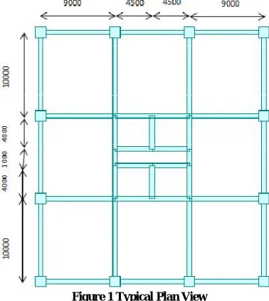
3.1 Analytical Model- A G+40 story RC frame (figure 1) is considered with beam size 500mmX750mm, column of size 1300mmX1300mm at top 10 floors reducing 100mm at each 10 floors. The core wall considered at the center is of thickness 600mm at top 10 floors and reducing 100mm at each 10 floors and the slab thickness taken is 150mm. The grade of concrete used in beams and slabs is M35, for core wall M50 and that in column is M50. The floor height is taken as 3m. Along with the dead load of the structure, live load of 2kN/m2 and a floor finish of 1kN/m2is also taken into account. The rate of construction sequence is assumed to be 3 days for each story construction. The structure is analysed using construction stage analysis option in Midas Gen, which analyses the structure step by step at every floor.
Figure 1 Typical Plan View
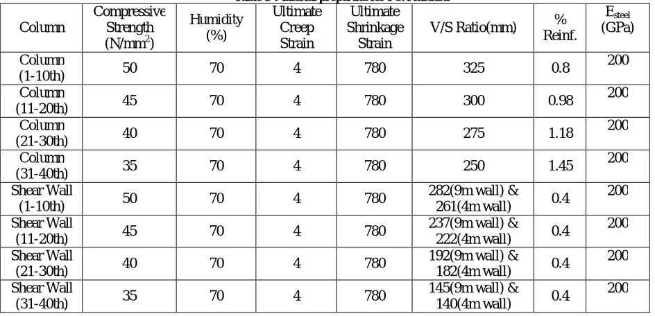
3.2 Material Properties-In order to define the properties of concrete shrinkage and creep, the PCA standard is used, and the concrete material properties are shown in table 1.
In V/S column in table 1, 9m wall is along X-direction and 4m wall is along Y-direction
Elatic strains of concrete with time are determined from compressive strength f’c(t) and elastic modulusEc(t), in
Equations (1) & (2)
′ ( ) =
. . (1)
( ) = 0.43 . ′ ( ) (MPa) (2)
Where t is age of concrete in days,
f28 is compressive strength of concrete at 28 days (MPa),
w is unit weight of concrete
PCA method suggests shrinkage strains with time in the form of Equation (3)
, = ( ) ∗ : ∗ ∗ ∗ (3)
:= Coefficients of volume to surface of member
=Shrinkage with time
=Shrinakge with relative humidity =Residual shrinkage of reinforced concrete
=
. . ( : ) (4)
Where, t is time in days after concrete pouring,
ts time in days of initial wet curing
v:s volume to surface area ratio
PCA method suggests creep strains with time in the form of Equation (5)
, = ∗( ) ∗ ∗ : ∗ ∗ ∗ (5)
Where, = Acting stress
( ) = Specific creep
= Age of concrete at loading
: = Member size
= Creep with time
= Creep with relative humidity
= Residual creep of reinforced concrete
= ( ).
. ( ) . (6)
t’ time in days to first loading after concrete pouring
Table 1 Material properties for PCA method
Column
Compressive Strength (N/mm2)
Humidity (%)
Ultimate Creep Strain
Ultimate Shrinkage
Strain
V/S Ratio(mm) % Reinf.
Esteel (GPa)
Column
(1-10th) 50 70 4 780 325 0.8
200
Column
(11-20th) 45 70 4 780 300 0.98
200
Column
(21-30th) 40 70 4 780 275 1.18
200
Column
(31-40th) 35 70 4 780 250 1.45
200
Shear Wall
(1-10th) 50 70 4 780
282(9m wall) &
261(4m wall) 0.4
200
Shear Wall
(11-20th) 45 70 4 780
237(9m wall) &
222(4m wall) 0.4
200
Shear Wall
(21-30th) 40 70 4 780
192(9m wall) &
182(4m wall) 0.4
200
Shear Wall
(31-40th) 35 70 4 780
145(9m wall) &
140(4m wall) 0.4
IV.RESULTSANDDISCUSSION
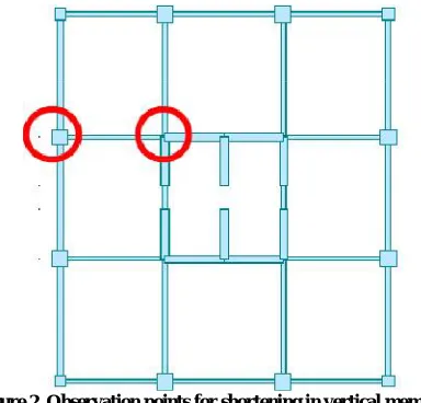
The observation points for the shortening of vertical members are selected at a column and a wall, highlighted in figure 2.From the analysis results, deformations due to the creep and shrinkage effects and elastic deformations, are shown in table 2. It shows that axial shortening increases with floor no. and maximum deformation is at top floor.
Deformation of column and wall is calculated after 3 years(1095 days) of building completion.
Figure 2 Observation points for shortening in vertical members
Table 2 The deformation of column by PCA method (1095 days)
Floors
Column Shear Wall
Elastic Deformation
Deformation Due to Creep & Shrinkage
Total Deformation
(mm)
Elastic Deformation
Deformation Due to Creep & Shrinkage
Total Deformation
(mm)
1 0.806529 0.994138 1.800667 0.435185 0.863059 1.298244
2 1.984953 2.458969 4.443921 1.070869 2.141488 3.212357
3 3.131204 3.895706 7.026911 1.689441 3.40265 5.092091
4 4.245531 5.304607 9.550138 2.291411 4.647644 6.939055
5 5.328166 6.6859 12.014067 2.876856 5.876713 8.753568
6 6.379328 8.039775 14.419103 3.445759 7.089784 10.535544
7 7.39922 9.366376 16.765596 3.998086 8.286662 12.284748
8 8.388031 10.66581 19.053841 4.533797 9.467057 14.000854
9 9.34593 11.938138 21.284069 5.052869 10.630513 15.683382
10 10.273066 13.183366 23.456432 5.555324 11.776136 17.331459
11 11.169553 14.401421 25.570975 6.041327 12.901763 18.94309
12 12.241259 15.962304 28.203562 6.634573 14.401702 21.036275
13 13.276453 17.489533 30.765986 7.20718 15.875436 23.082616
14 14.275318 18.983132 33.25845 7.759447 17.326113 25.085559
15 15.238013 20.44305 35.681062 8.291417 18.754637 27.046054
17 17.055428 23.261375 40.316803 9.294395 21.54549 30.839885
18 17.910366 24.619428 42.529793 9.765358 22.907405 32.672763
19 18.729565 25.943073 44.672638 10.215968 24.246503 34.462471
20 19.513073 27.231983 46.745055 10.646312 25.562161 36.208473
21 20.260898 28.485696 48.746594 11.056735 26.853081 37.909816
22 21.160328 30.099162 51.259491 11.573366 28.550687 40.124053
23 22.015998 31.666408 53.682406 12.063441 30.212015 42.275456
24 22.827949 33.186979 56.014927 12.52756 31.840564 44.368123
25 23.596188 34.660247 58.256435 12.965863 33.437268 46.403131
26 24.320696 36.085539 60.406235 13.37838 35.002227 48.380607
27 25.6383 38.788709 64.427009 14.126088 38.035711 52.161799
29 25.001426 37.462019 62.463445 13.765117 36.535179 50.300296
28 26.231209 40.06456 66.295769 14.461342 39.503382 53.964723
30 26.780003 41.288399 68.068401 14.771062 40.937751 55.708812
31 27.284481 42.458713 69.743194 15.055843 42.338358 57.394202
Floors
Column Shear Wall
Elastic Deformation
Deformation Due to Creep & Shrinkage
Total Deformation
(mm)
Elastic Deformation
Deformation Due to Creep & Shrinkage
Total Deformation
(mm)
32 27.880028 43.943098 71.823125 15.424427 44.159537 59.583964
33 28.419113 45.351524 73.770637 15.756835 45.923268 61.680103
34 28.901439 46.68136 75.582798 16.054159 47.633566 63.687725
35 29.32664 47.929796 77.256436 16.316665 49.29107 65.607735
36 29.694281 49.093521 78.787802 16.544405 50.895099 67.439504
37 30.003837 50.168701 80.172539 16.73736 52.444392 69.181752
38 30.254662 51.150483 81.405145 16.89545 53.937073 70.832523
39 30.445915 52.032941 82.478856 17.018516 55.370829 72.389345
40 30.576382 52.807948 83.38433 17.106203 56.742187 73.84839
Table 3 shows the comparison between axial shortening amounts at the 41th story by PCA method.
Table 3 Comparison between Axial Shortening Amounts at the 41th Story by PCA Method
Construction Stage Analysis
Elastic Creep and Shrinkage Total
Shortening at Column 30.64mm 53.46mm 84.10mm
Ratio (%) 36.43 63.57 100
Shortening at Shear Wall 17.16mm 58.04mm 75.20mm
Ratio (%) 22.82 77.18 100
Comparison Column > Shear Wall Column > Shear Wall Column > Shear Wall
The column exhibits the maximum vertical displacement of 84.10mm at the highest story, and the wall exhibits the maximum vertical displacement of 75.20mm at the highest story. These values gradually increase with the increase in no. of stories. Column shows maximum elastic as well as inelastic shortening as compared to shear wall.
For a column, elastic shortening contributes 36.43% of total shortening and shortening due to creep and shrinkage is 63.57%.
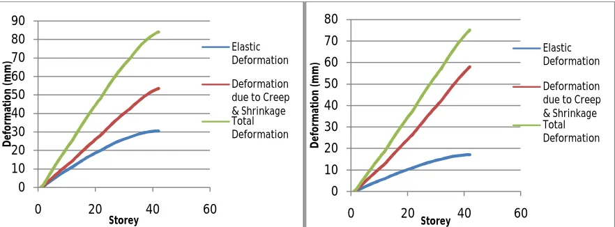
Figure 3 and figure 4 shows the distribution graphs of the vertical deformations by stories for the column and wall, respectively. In both fig. deformation due to creep and shrinkage is more than elastic deformation. Thus it shows effect of inelastic deformation on RC structure.
Also, in both fig. total axial shortening in column is more than shortening in wall.
Figure 3 Vertical deformationof column by PCA methodFigure 4 Vertical Deformation of shear wall by PCA method
V. CONCLUSION
The construction stage analysis reflecting deformations due to creep and shrinkage of the 40-story reinforced concrete structure consisting of core walls and exterior frame shows the following effects:
Inelastic shortening(due to creep and shrinkage) is 1.75 times the elastic shortening for a column and 3.38 times for a wall element.
0 10 20 30 40 50 60 70 80 90
0 20 40 60
D e fo rm at io n ( m m ) Storey Elastic Deformation Deformation due to Creep & Shrinkage Total Deformation 0 10 20 30 40 50 60 70 80
0 20 40 60
The proportion of the deformations due to creep and shrinkage that contribute to the total amount of deformations is63.57% for the column, and 77.18% for the shear wall. Therefore for concrete buildings, deformations due to the creep and shrinkage must be considered.
Since there are considerable amounts of deformations due to creep and shrinkage, their effects must be considered in analysis. This fact becomes more significant forhigh-rise construction or for structures with longer construction periods.
REFERENCES
[1] Fintel, M., and Khan, F. R.,“Effects of Column Creep and Shrinkage in Tall Structures Prediction of Inelastic Column Shortening”, ACI
Journal, Vol. 66, No. 12, pp. 957-967, 1969.
[2] S. C. Chakrabarti, G. C. Nayak and S. K. Agarwala, “Effect of sequence of construction in the analysis of multi storeyed building frame”,
Building and Environment, Vol. 13, No. 1, pp.1–6, 1978.
[3] Fintel, M., S. K. Ghosh, and H. Iyengar, "Column Shortening in Tall Buildings-Prediction And Compensation." Publ. EB108 D, Portland
Cement Association, Skokie 3: 1-34, 1987.
[4] [M. M. Elnimeiri and M. R. Joglekar, “Influence of Column Shortening in Reinforced Concrete and Composite High Rise Structures” Special
Publication Vol 117, 1989.
[5] Uy, B, “Concrete-Filled Fabricated Steel Box Columns for Multi Storey Buildings: Behaviora and Design”, Construction Research
Communication Limited, Vol. 28 pp 150-158, 1998.
[6] K. Sakata, T. Ayano, K. ImamotoAnd Y. Sato, ''Database of creep and Shrinkage Based on Japanese Research”, RILEM and ACI, 2005
[7] M. T. R. Jayasinghe and W. M. V. P. K. Jayasena,“Effect of Relative Humidity on Absolute and Differential Shortening of Columns &Walls
in Multistory Reinforced Concrete Buildings”,Practice Periodical on Structural Design and Construction , Vol. 10, No. 2, pp. 88-97,2005
[8] Taehun ha, Sungho Lee, Bohwan Oh, “RC High-Rise Building Construction Based on Case Studies of Displacement & Guidelines for
Building Movement During Construction of High-Rise Buildings”, South Korea Concrete Institute Conference, Vol.20 No.5, pp 1-15, 2007.
[9] A. Vafaia, M. Ghabdiana, H.E. Estekanchi and C.S. Desai,“Calculation of Creep and Shrinkage in Tall Concrete Buildings Using Nonlinear
Staged Construction Analysis” Asian Journal of Civil Engineering (Building And Housing) Vol. 10, No. 4 pp 409-426, 2009.
[10] H. N. Praveen, Moragaspitiya, David. P. Thambiratnam, Nimalparera, Tommy H. T. Chen, “A Numerical Method to Quantify Differential