ISSN(Online): 2319-8753 ISSN (Print): 2347-6710
International Journal of Innovative Research in Science,
Engineering and Technology
(An ISO 3297: 2007 Certified Organization)
Website: www.ijirset.com
Vol. 6, Issue 6, June 2017
Performance Enhancement of Refrigeration
Cycle by Employing a Heat Exchanger
Shoeb Inamdar 1, H. S. Farkade 2
P.G. Student, Department of Mechanical Engineering, Govt. College of Engg. Amravati. Maharashtra, India1
Assistant Professor, Department of Mechanical Engineering, Govt. College of Engg. Amravati. Maharashtra, India2
ABSTRACT: Refrigeration system works on the second law of thermodynamics specifically on the Clausius statement
which summarizes that the refrigerator is nothing but a reversed heat engine which consumes energy in the form of work to transfer heat from Low temperature body to high temperature body.
Refrigeration system mainly works on Vapour Compression Refrigeration cycle (VCR), in simple VCR cycle the refrigerant after condensation enters into the region of interest after throttling i.e. from where the heat is to be removed. Greater the extent of condensation that ensures the low temperature vapour in cooling region. To enhance the performance means to enhance the cooling capacity but with adjustment of the consequences of doing so. The heat exchanger is installed between the suction line and the discharge line which transfer the heat from low temp low pressure suction line to the high temperature high pressure discharge line also known as Liquid Suction Heat Exchanger. The liquid in the discharge line gets sub cooled and the vapour gets superheated due to which the compressor works increases due to increase in specific volume. In this experimentation various parameters change. This paper identifies the ways of installing the heat exchanger and to find the best suitable way and to analyze the impacts of experimentation on various operating parameters.
KEYWORDS: Clausius statement, VCR, Cooling capacity, Subcooling.
I. INTRODUCTION
Refrigeration system takes energy in the form of work and transfer heat from low temperature to high temperature to get the desired cooling therefore it consumes a large amount of electrical energy to do so, as a result many methods have been developed by researchers to improve the system performance [2].The commercial refrigeration systems (freezer and air conditioner) consume approximately 50- 60% of energy total. Installed heat exchanger (HX) uses an internal heat exchanging technique to subcool the discharge liquid, which transfers heat from the condenser outlet to the compressor suction, may lead to an increase in the cooling capacity produced by the evaporator. This method is called subcooling using liquid suction heat exchanger (LSHX). The most important effect of the use of LSHX is the increase in cooling capacity because of the lower quality of refrigerant entering the evaporator, consequently the evaporator absorb more heat from the ambient. On the other hand due to the liquid suction heat exchanger (LSHX) the vapour to the suction of compressor get superheated
.
ISSN(Online): 2319-8753 ISSN (Print): 2347-6710
International Journal of Innovative Research in Science,
Engineering and Technology
(An ISO 3297: 2007 Certified Organization)
Website: www.ijirset.com
Vol. 6, Issue 6, June 2017
Figure1. LSHX Subcooler Schematics and P-h Plot
In employment of the LSHX to enhance the performance the factors which dominate mainly are the proper selection of the refrigerant and the operating ambient temperature. Some of the famous refrigerant which suit to this design are R22, R290, R134a etc. because R22 has a high global warming potential (GWP), the near future this refrigerant shall be phased out and R290 (propane) is recommended as a substitute refrigerant for R22. The R290 is a natural refrigerant, abundant and relatively cheaper than that of R22. Many studies reported that replacement of R22 with R290 in freezer resulted in COP improvement. The discharge temperature of R290 at an ambient temperature greater than 40 0C is above 110 0C hence this puts limitation to the use of this refrigerant [5].
As can be seen from the Pressure (bar)-Enthalpy (kJ/kg) (P-h) plot Fig.1. that
In the simple VCR cycle without LSHX:
Refrigerating effect = h1-h4 (kJ/kg)
Compressor work = h2-h1 (kJ/kg)
Hence,
COP = R.EC.W = (h1-h4)/ (h2-h1)
In the simple VCR cycle with LSHX:
Refrigerating effect = h1-h4, (kJ/kg)
Compressor work = h2-h1, (kJ/kg)
The refrigerating effect is increased and the compressor work also increases but to certain extent hence the overall COP Increases.
COP = R.EC.W
= (h1-h4,)/ (h2-h1,)
Nomenclature
Re Reynold’s number Nu Nusselt number
Pr Prandtl number m Mass flow rate of refrigerant
h Heat transfer Coefficient (W/m2k) L Length of heat exchanger
COP Coefficient of performance V Velocity of fluid (m/s)
Cp Specific heat at const. Pressure Greek symbols
U Overall heat transfer coefficient ρ density of fluid, kg/m3
ISSN(Online): 2319-8753 ISSN (Print): 2347-6710
International Journal of Innovative Research in Science,
Engineering and Technology
(An ISO 3297: 2007 Certified Organization)
Website: www.ijirset.com
Vol. 6, Issue 6, June 2017
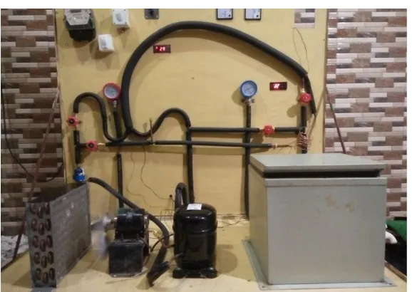
II. EXPERIMENT SET-UP
The simple VCR system needs to be developed first so as to get the initial readings and then from those readings of suction and discharge all the flow properties are calculated and then the Heat exchanger is designed from this data.
The cycle of the system under study was composed of five basic components, i.e., a compressor, an evaporator, a condenser, capillary tube and a liquid line filter–drier. A Single-phase, 220 V, reciprocating compressor originally designed for R134a systems was used. The input power of the compressor within the system varied between 230 and 300 W. The major ingredient of the compressor lubricant was mineral oils. A silica gel drier filter was used to absorb the moisture. Compact forced air cooled type condenser was used for their good heat transfer performances. Evaporator section was made by Galvanized iron sheet chamber box for minimizing the heat loss, the evaporator tank was well insulated by puff. The refrigerants used is R134a. Some other measuring and controlling components were used in the system, that were, an electrical switch, an energy meter, a voltmeter, an ampere meter, a digital thermostat for controlling the evaporator temperature, bourdon tube type low pressure gauge and high pressure gauge, thermistor based temperature indicator and gas flow control valves.
Figure 1: Initial Simple VCR Setup
A. Specifications of Experimental Set-up
Following are the specifications of the various components of the used in the experimental set-up.
In the experimental set up, KCE444HAG, Hermetically sealed, Reciprocating type compressor was used.The
compressor having the cooling capacity of 1077 W and an average current consumption of 2A at subzero evaporator temperature and Power consumption of 450 W.
In the experimental set up, compact 10inch * 11 inch * 3 row type air cooled condenser was used. Here air was circulated by fan motor of power 1/83 HP.
In the experimental set up, DM 50 type filter-drier was used, which contains silica gel for absorbing the moisture content from the working medium.
In the experimental set up capillary tube of 0.050 inch diameter is used.
ISSN(Online): 2319-8753 ISSN (Print): 2347-6710
International Journal of Innovative Research in Science,
Engineering and Technology
(An ISO 3297: 2007 Certified Organization)
Website: www.ijirset.com
Vol. 6, Issue 6, June 2017
In the experimental set up, two bourdon tube type mechanical pressure gauges were used. First one was high pressure gauge (Range 0300 psi) for discharge pressure and other one was low pressure gauge (Range 30 -150 psi) for suction pressure were used here.
In the experimental set up, digitally operated electronic type thermostat was used to indicate and control the temperature in evaporator tank. The sensor used are thermister based sensor.
In the setup the sub zero SZ 7569 is used with the selector switch as a temperature indicator it also includes thermister based sensors.
III. DATA REDUCTION AND HEAT EXCHANGER DESIGN
All of the following data refers to the maximum design condition hence every reading is taken at maximum value it reaches. All Properties of refrigerant R134a is taken from property table at maximum design conditions.
A. System Configuration :
Refrigerant – R134a
System Pressure – 70 Psi. Mass of refrigerant – 205 gms.
B. Pressure Readings:
Both suction and discharge pressure are unaffected by the subcooling and superheating. Maximum Suction Pressure = 1.5 kgf/cm2 (Gauge)
= 2.48 bar. ( Abs. at 34 and 38 0C )
Maximum Condenser Pressure = 15 kgf/cm2 (Gauge)
= 15.722 bar. (Abs. at 34 and 38 0C)
C. Temperature Readings:
Temp. at entry to compressor – T1
Temp. at exit to compressor – T2
Temp. at exit to condenser – T3
Temp. after expansion – T4
Mass flow rate from swept volume and speed of compressor is given by:
Mass flow rate (m) = Volume. (3.1)
m = ×A×V where V- Velocity (m/s) (3.2) Reynold’s Number is given by
Re = ×
(forced convection Analysis) (3.3)
Prandtl’s Number is given by
Pr = × (3.4)
From forced convection analysis the nusselt no. is given by
ISSN(Online): 2319-8753 ISSN (Print): 2347-6710
International Journal of Innovative Research in Science,
Engineering and Technology
(An ISO 3297: 2007 Certified Organization)
Website: www.ijirset.com
Vol. 6, Issue 6, June 2017
Then, overall heat transfer coefficient is given by:
= + (3.6)
Finally, the size of heat exchanger is given by the heat transfer equation
Q = m*Cp*T = U*A*m (3.7)
After getting the size of the heat exchanger the heat exchanger is added in the basic initial set up in the form of annular pipes of suction and discharge lines. the experimentation is performed for the different loads at different ambient temperature and the following results and data is obtained.
Figure 2: Final VCR System with LSHX line Diagram
ISSN(Online): 2319-8753 ISSN (Print): 2347-6710
International Journal of Innovative Research in Science,
Engineering and Technology
(An ISO 3297: 2007 Certified Organization)
Website: www.ijirset.com
Vol. 6, Issue 6, June 2017
IV. RESULTS AND DISCUSSION
The experimentation is performed for the different loads in the form of waters at different ambient temperature of 30 0C,34 0C and 38 0C with and without heat exchanger and then compared and the following results and data is obtained.
A. Comparison of cooling intensity w.r.t time between simple VCR and VCR with LSHX
Figure 4: Cooling intensity comparison ( 12 Kg Load)
As we can see from the graph above that the cooling intensity of the system with LSHX is higher than that of the simple VCR setup as can be seen in the run of 35 min. for 12 kg load water the simple VCR system causes the temperature drop of 17 0C where as the System of LSHX causes the same amount of load water the temperature fall of 21 0C within the same amount of time.
B. Effect of Subcooling on Discharge Temperature
Figure 5: Degree of Subcooling Vs Dsicharge Temperature. (12 kg.)
0 10 20 30 40
0 10 20 30 40
L oa d Wa te r T em p . (C ) Time (min)
Cooling Intensity Comparison
(12 Kg Load)
Simple VCR(At 38 C)
0 20 40 60 80 100
0 2 4 6 8 10 12
D si ch a rge T em p . C
Degree of Subcooling
Effect of Subcooling On Discharge Temp.
(12 Kg Load)
At 38 C
At 34 C
ISSN(Online): 2319-8753 ISSN (Print): 2347-6710
International Journal of Innovative Research in Science,
Engineering and Technology
(An ISO 3297: 2007 Certified Organization)
Website: www.ijirset.com
Vol. 6, Issue 6, June 2017
As can be seen from the graph above that if we go on increasing the degree of subcooling then the discharge temperature increases though the condenser outlet temperature almost remains constant. As the degree of subcooling increases due to that the amount of superheating of the suction line increases that to the greater extent as compared to the degree of subcooling as the specific heats of both the hot and cold fluid is different hence the degree of superheating dominates and due to that the compressor work increases to some amount and the refrigerant is compressed to some higher temperature and hence same increases.
At higher ambient temperature the condenser outlet temperature also increases although it varies in the range of only 3 0C still that causes the significant rise in the superheating due to high specific heat hence at higher ambient temperature the discharge from the compressor increases to higher value.
C. Effect of ambient temperature on Compressor work
The graph below illustrates the effect of the ambient temperature on the compressor work on both
the simple VCR and the LSHX system
.
Figure 6: Compressor work Vs Ambient temperature (12 Kg)
. As can be seen that at lower ambient temperature the current consumption form the compressor is less this is due to that at lower ambient temperature the condensation process goes good and the liquid itself subcool in the condenser and then expands to very low temperature and pressure and the entire system operates on the pressure values which are less than the maximum pressure ranges of the system due to that the power consumption is less at ower temperature and at higher ambient temperature the system operates at higher pressure ranges and hence the current consumption of both the system increases.
0 0.1 0.2 0.3 0.4 0.5 0.6 0.7
Ambient Temp.(C)
30 34 38
Ambient Temp. Vs Compressor Work
(12 Kg Load)
Comp. Work for Simple VCR(kW)
ISSN(Online): 2319-8753 ISSN (Print): 2347-6710
International Journal of Innovative Research in Science,
Engineering and Technology
(An ISO 3297: 2007 Certified Organization)
Website: www.ijirset.com
Vol. 6, Issue 6, June 2017
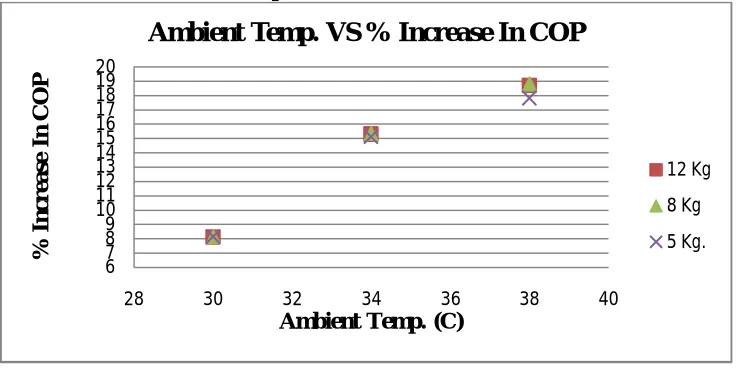
D. Increase in the COP with LSHX Over Simple VCR
Figure 7: % improvement in COP with Ambient Temperature
The graph above illustrates that the COP with the LSHX increases but how its improvement varies relative to the ambient temperature that phenomenon is explained in the graph above.
As can be seen from the graph above that at lower ambient temperature of 300C the % increase of LSHX over simple VCR is 8 % this is due to fact that at lower ambient temperature the condensation itself goes to good extent in the condenser and the condensate comes out at lower temperature and hence effectiveness of the LSHX is not that much dominant at lower ambient temperature.
At higher ambient temperature say at 380C the % increase in the COP with LSHX over VCR is 18.71% this is due to the fact that at higher ambient temperature the condenser outlet comes at higher temperature and the expands from there and due to that the enthalpy content of the fluid remains higher due that the heat absorbing capacity decreases and hence by subcooling that condensate in the LSHX the enthalpy is decreased first and the throttled to extract the heat from evaporator due to that the COP improves.
V. CONCLUSION
The use of LSHX leads us to conclude the improvement in the performance of the system even though the power consumption of the compressor increases to some amount the refrigeration effect increases to greater extent and hence the COP increases and that improvement dominates at higher ambient temperatures and the cooling intensity also increases as a function of time.
The COP of the system increases with LSHX.
Input power consumption increases to some extent with LSHX.
Discharge temperature increases due to superheating of the refrigerant in LSHX.
Effectiveness of the LSHX increases as the ambient temperature increases.
REFERENCES
[1]. B.A. Qureshi, S.M. Zubair. 2012. The efffect of refrigerant combination of performance of a vapour compression refrigeration system with dedicated mechanical sub-cooling. International Journal of Refrigeration. 35: 47-57.
[2]. B.A. Qureshi, M. Inam, M.A. Antar, S.M. Zubair. 2013. Experimental energetic analysis of a vapour compression refrigeration system with dedicated mechanical sub-cooling. Applied Energy. 102: 1035- 1041.
[3]. S.S. Klein, D.T. Reindl, K. Brownell. 2000. Refrigeration system performance using liquidsuction heat-exchanger. International Journal of Refrigeration. 23: 588-596.
6 7 8 9 10 11 12 13 14 15 16 17 18 19 20
28 30 32 34 36 38 40
% I n cr ea se I n C O P
Ambient Temp. (C)
Ambient Temp. VS % Increase In COP
12 Kg
8 Kg
ISSN(Online): 2319-8753 ISSN (Print): 2347-6710
International Journal of Innovative Research in Science,
Engineering and Technology
(An ISO 3297: 2007 Certified Organization)
Website: www.ijirset.com
Vol. 6, Issue 6, June 2017
[4]. G. Lorentzen. 1995. The use of natural refrigerants: a complete solution to the CFC/HCFC predicament. International Journal of Refrigeration. 18: 190-197.
[5]. K. Sumeru, H. Nasution, F.N. Ani. 2013. Numerical study on ejector as an expansion device in a split-type air conditioner for energy savings. Journal of Engineering Thechnological Sciences. 45: 101-111.
[6]. K. Sumeru, S. Sulaimon, H. Nasution, F.N. Ani. 2014. Numerical and experimental study on an ejector as an expansion device in a split-type air conditioner for energy savings. Energy and Buildings. 79: 98-105.
[7]. G. Pottker, P. Hrnjak P. 2015. Experimental investigation of the effect condenser subcooling in R134a and R1234yf air-conditioning systems with and without internal heat exchanger. International Journal of Refrigeration. 50: 104-113.
[8]. Conditioning Engineers, ISBN 1-883413-54-0, Chapter 2, (1998).
[9]. Tube-Liquid-suction Heat Exchanger Performance with R152a", ASHRAE Transactions, Vol. 101, No. 1, pp. 124-135, (1995a).