ISSN(Online): 2319-8753 ISSN (Print): 2347-6710
I
nternational
J
ournal of
I
nnovative
R
esearch in
S
cience,
E
ngineering and
T
echnology
(An ISO 3297: 2007 Certified Organization)
Website: www.ijirset.com
Vol. 6, Issue 8, August 2017
A Survey Report on Fiber Optic Sensors
G. Alekya
Asst.Prof, Department of Physics, Gurunanak Engg College, Ibrahimpatnam, R. R. Dist. Telangana, India
ABSTRACT: As the technology changes use of instruments and accuracy also increases. Besides the advantages of fiber optic sensor, the cost is reduces and evaluation will be increase day by day. Fiber optic sensor are used in place of electrical sensor and used along with optoelectronics devices. This paper covers different types of fiber optic sensors their application and their practically simulated results.
KEYWORDS: Mach Zehnder interferometer sensor, fiber Bragg grating, Michelson sensor, fiber optic gyroscope, micro band sensor, evanescent wave sensor
I. INTRODUCTION
With the invention of laser in 1960‟s, researcher gets innovative idea to develop the optical system for data
transmission. Laser could send more data compare to microware, and other electrical systems. The first experiment with laser to transmit laser beams in air without any wired connection. Researchers also conducted experiments by transmitting laser beam through different types of waveguides. First they used plastic fiber as a waveguide. Then glass fiber became the preferred medium for data transmission of light. Using glass fiber, the losses due to coaxial cable is reduced. But earlier glass fiber had losses around 1000 dB/km. This output makes the impractical for communication purpose.[1] After that the scientist concluded that signal losses in the transmission were because of impurities in the fiber material. By removing these impurities in the fiber material, it was possible to made low loss fiber. Then invention of corning glass works made a multimode fiber with losses. The losses were under 20 dB/km. The corning glass works also made a high silica-core multimode optical fiber with 4 dB/km loss.[1] Optical Fiber has ability to carry gigabits of information at the speed of light. Similarly there was improvement in optoelectronics component and also its cost reduction makes the new product areas for optical fiber field. Soon it discovered the fiber optic sensor, with material loss almost disappearing and the sensitivity for detection of the losses increasing, one could sense changes in phase, intensity ,wavelength and polarization from outside perturbations on the fiber itself. so from this the fiber optic sensing came in the field.[1]
Parallel with these developments, fiber optic sensor technology has a significant user friendly technology related with optoelectronic and fiber optic communication industry.[1]Fiber optic sensor technology has been driven by the development and mass production of component to support the fiber optic communication industries. As component prices have decreased and quality improvements have been made, fiber optic sensors replace traditional sensors.[1] Fiber optic sensors are good excellent for monitoring environmental changes and they offer many advantages over traditional electrical sensors. The advantages are as under.
They are easy integrated with wide structures, including composite materials, with little interference due to small size and cylindrical geometry.
They do not conduct any electrical current.
They are immune to electromagnetic interference and radio frequency interference.
They are lightweight compare to traditional sensors.
They are robust and more resist to harsh environments.
They are highly sensitive.
Their multiplexing capability to form sensing networks.
They have remote sensing capability.
ISSN(Online): 2319-8753 ISSN (Print): 2347-6710
I
nternational
J
ournal of
I
nnovative
R
esearch in
S
cience,
E
ngineering and
T
echnology
(An ISO 3297: 2007 Certified Organization)
Website: www.ijirset.com
Vol. 6, Issue 8, August 2017
Till date, fiber optic sensors are widely used to monitor a wide range of environmental parameters like position ,vibration ,strain ,pressure ,humidity ,temperature ,chemicals ,current, electrical fields ,viscosity and many other environmental factors.[1]
II. BASIC OF OPTICAL FIBER
Optical fiber composed of mainly three parts: the core, the cladding and the buffer or coatings. The basic structure of optical fiber is in figure 1.
Figure 1.Basic structure of Optical Fiber
1. The core is the cylindrical part of the fiber. It is made up of dielectric material, and generally made up of glass. The light propagates through mainly core.
2. The cladding is the outer layer of the core, and it is also made up of dielectric material with different refractive index. The refractive index of the cladding is less than the refractive index of core material. This part is generally made up of glass or plastic material. It decreases loss of light from core in to surrounding air. It also decrease the scattering loss at the surface of the core, and protect the fiber from absorbing surface contaminants and add mechanical strength to the fiber[1].
3. The outer coating or buffer or jacket is an outer most layer to protect an optical fiber from physical damages. This part is made up of plastic material. This material is elastic in nature to prevent abrasions.[1]
A .MAIN PRINCIPLE OF OPTICAL FIBER
The main principle of optical fiber for light propagation is based on the “total internal reflection”. The angle at which the total internal reflection occurs is called the critical angel of that medium. This angel is determining by Snell‟s law [1]. Optical fiber is basically divided in two types.
ISSN(Online): 2319-8753 ISSN (Print): 2347-6710
I
nternational
J
ournal of
I
nnovative
R
esearch in
S
cience,
E
ngineering and
T
echnology
(An ISO 3297: 2007 Certified Organization)
Website: www.ijirset.com
Vol. 6, Issue 8, August 2017
Figure 2.Principle of optical fiber Now based on refractive index it divided in two types
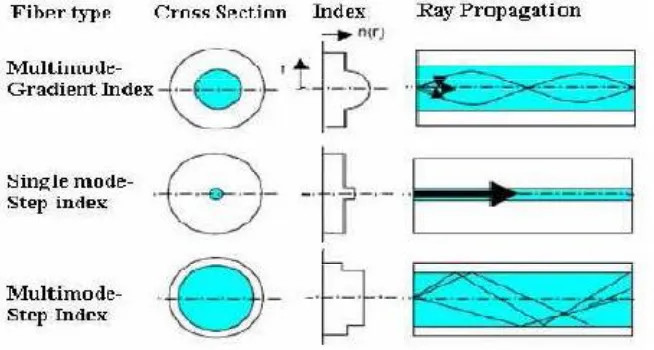
1. Step index fiber 2. Graded index fiber
Based on propagation mode it divided in two types 1. Single mode fiber
2. Multimode fiber
So by combining these two types of fiber they are combinable called 1. Single mode step index fiber
2. Single mode graded index fiber 3. Multimode step index fiber 4. Multimode graded index fiber.
But single mode graded index fiber is not used because of single mode fiber do not require more size of core for propagation. So remaining three types of fiber are mostly used in optical fiber field. In step index fiber, there is constant index profile over the whole cross section. In graded index fiber, the fiber has nonlinear, rotationally symmetric index profile, which falls off the center of the fiber outwards.
ISSN(Online): 2319-8753 ISSN (Print): 2347-6710
I
nternational
J
ournal of
I
nnovative
R
esearch in
S
cience,
E
ngineering and
T
echnology
(An ISO 3297: 2007 Certified Organization)
Website: www.ijirset.com
Vol. 6, Issue 8, August 2017
III. BASIC PRINCIPLE OF FIBER OPTIC SENSOR
The basic principle of optical fiber sensor’s block is as shown in figure. It consists of source, transducer, measurands, detector and electronics devices. For data transmission this system uses optical fiber. As optical source it use led, laser or laser diode. As sensing or modulator element (which transduces the measurands to an optical signal). As a detector it uses pin diode or photo detector. And as electronic devices it use oscilloscope, spectral analyzer.
Figure 4.Basic block diagram of fiber optic sensor
Fiber optic sensors are classified based on the sensing location, the operating principle and their application.
1. Based on the sensing location: on this basis the fiber optic sensor classified as intrinsic or extrinsic sensor. 2. Based on the operating principle: On this basis the fiber optic sensor classified as their modulation or demodulation methods. They are as intensity, a phase, a frequency and a polarization sensor.
3. Based on the application: On this basis the fiber optic sensor classified as under.
Physical sensor: It is used to measure any physical quantity like temperature, pressure, stress, velocity
Chemical sensor: It is used for PH measurements, gas analysis and for checking the chemical contents
Biomedical sensor: It is used in biomedical applications like measurement of blood flow, glucose contents, heart beat checking.[1]
IV. FIBER OPTICS SENSORS
A. INTRINSIC AND EXTRINSIC SENSOR
ISSN(Online): 2319-8753 ISSN (Print): 2347-6710
I
nternational
J
ournal of
I
nnovative
R
esearch in
S
cience,
E
ngineering and
T
echnology
(An ISO 3297: 2007 Certified Organization)
Website: www.ijirset.com
Vol. 6, Issue 8, August 2017
Figure.5 Intrinsic and extrinsic sensor [1]
In extrinsic fiber optic sensor, the fiber simply uses to carry light to and from the external optical device where the sensing takes place. In this case the fiber is just the component that carries light.[1] In extrinsic fiber the transducer, that is not an optical fiber, is modulating the light, out of a physics phenomenon: for instance a vibration, and this modulated light is then sent inside the fiber where it will propagate up to a device converting, at the output of the fiber, the modulated light into a modulated electronic signal.[2] Extrinsic sensors are generally not dedicated to high level measurements, but they are convenient for applications where low resolution and low cost are requested. Intrinsic Fiber optic sensor is different from others. The conversion of the modulation of a physic parameter is done by a portion of an optical fiber. These sensors are much more difficult to elaborate, but they have the best performances.
A change in pressure, temperature, curvature and so on will modify such properties of the optical fiber propagating light as its phase, polarization, amplitude or spectra. For these physical parameters intrinsic fiber optic sensor can be used as a sensor for change.[2]
B. INTENSITY BASED FIBER OPTIC SENSOR
Intensity based fiber optic sensors senses the change in the intensity of light which is travelled through the fiber. It relies on signal undergoing some loss. The signal made by using an apparatus to convert what is being measured in to a force that bends the fiber and cause attenuation of the signal. Another way to attenuate the signal is absorption or scattering the signal.[1] The intensity based fiber sensor require more light and for that the usually uses multimode large core fibers. These sensors are simple and its cost is low. They can be possible to multiplex and it is able to perform as a real distributed sensor. But it has drawback also that it has relative measurements and variations in the source of light may lead to false readings if we do not referencing the system which one we use. There are some mechanisms that can produces absorption and attenuation in the optical intensity propagated by the optical fiber.[1] Some sensors that have principle of intensity based fiber optic sensor are as under:
1. Micro band sensor 2. Even scent wave sensor
ISSN(Online): 2319-8753 ISSN (Print): 2347-6710
I
nternational
J
ournal of
I
nnovative
R
esearch in
S
cience,
E
ngineering and
T
echnology
(An ISO 3297: 2007 Certified Organization)
Website: www.ijirset.com
Vol. 6, Issue 8, August 2017
Figure 6.Microbend sensor [3]
The micro bend sensor is basically displacement sensor. The basic design is shown in figure 6. Corrugated plates, called deformer plates, squeeze optical fiber under measured perturbation and thereby induce micro bending.
This causes coupling between guided and continuum of cladding modes, which results in irreversibly leak of the optical power from the fiber [3] the micro bend sensitivity can be enhanced by the proper constriction of deformer plates. It was shown that mechanical period of the deformer must match expression (1)
in the case of graded index fiber in order to achieve maximum micro bend sensitivity, where a is core radius and is refractive index Difference [5] Measurements can also be performed in a similar method by replacing the cladding with a material such as an organic dye whose optical properties can be changed by the chemical under investigation.[1] Another type of intensity based fiber optic sensor is the evanescent wave sensor. This sensor utilizes the light energy which leaks from core to cladding. These types of sensors are use in the chemical plants or biomedical uses.[1]
Figure 7. Even scent wave sensor
ISSN(Online): 2319-8753 ISSN (Print): 2347-6710
I
nternational
J
ournal of
I
nnovative
R
esearch in
S
cience,
E
ngineering and
T
echnology
(An ISO 3297: 2007 Certified Organization)
Website: www.ijirset.com
Vol. 6, Issue 8, August 2017
C. WAVELENGTH MODULATED FIBER OPTIC SENSOR
Wavelength modulated fiber optic sensors use changes in the wavelength of light for detection. Fluorescence sensors, black body sensors, and the Bragg grating sensor are examples of wavelength-modulated sensors.
Figure 8.Fluorescence wave sensor
Figure 8.shown the fluorescence wave fiber optic sensor. It is made up of fluorescent material. The end tip sensor, light propagated down the fiber to a probe of fluorescent material. The resultant signal is captured by the same fiber and directed back to an output demodulator. [1] Fluorescent based fiber sensors are widely used for medical applications, chemical sensing and physical parameter measurements such as temperature, viscosity and humidity.[1]
Figure 9.Blackbody sensor
Another the simplest wavelength based sensor is the blackbody sensor as shown in Figure 9. A blackbody cavity is placed at the end of an optical fiber. When the cavity rises in temperature it starts to glow and act as a light source. Detectors in combination with narrow band filters are then used to determine the profile of the blackbody curve. This type of sensor has been used to measure temperature to within a few degrees centigrade under intense RF fields.[1]
ISSN(Online): 2319-8753 ISSN (Print): 2347-6710
I
nternational
J
ournal of
I
nnovative
R
esearch in
S
cience,
E
ngineering and
T
echnology
(An ISO 3297: 2007 Certified Organization)
Website: www.ijirset.com
Vol. 6, Issue 8, August 2017
Figure 10. Is fiber Bragg grating sensor. Fiber Bragg Gratings are made by laterally exposing the core of a single-mode fiber to a periodic pattern of intense ultraviolet light. The exposure produces a permanent increase in the refractive index of the fiber's core, creating a fixed index modulation according to the exposure pattern. This fixed index modulation is called a grating.[8] At each periodic refraction change a small amount of light is reflected. All the reflected light signals combine coherently to one large reflection at a particular wavelength when the grating period is approximately half the input light's wavelength. This is referred to as the Bragg condition, and the wavelength at which this reflection occurs is called the Bragg wavelength. Light signals at wavelengths other than the Bragg wavelength, which are not phase matched, are essentially transparent. This principle is shown in Figure 10.[8]
A fiber Bragg grating (FBG) is a type of distributed Bragg reflector constructed in a short segment of optical fiber that reflects particular wavelengths of light and transmits all others. This is achieved by creating a periodic variation in the refractive index of the fiber core, which generates a wavelength specific dielectric mirror. A fiber Bragg grating can therefore be used as an inline optical filter to block certain wavelengths, or as a wavelength-specific reflector.[1]
D. PHASE MODULATED FIBER OPTIC SENSOR
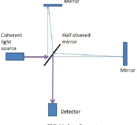
Phase modulated sensors use changes in the phase of light for detection. The optical phase of the light passing through the fiber is modulated by the field to be detected. This phase modulation is then detected interferometerically, by comparing the phase of the light in the signal fiber to that in a reference fiber. Interferometers are widely used in science and industry for the measurement of small displacements, refractive index changes and surface irregularities.[1]
FIG 11. Interferometer
As a shown in figure 11 a compensating cell made of the same type of glass as the test cell would be placed in the path of the reference beam to match the test cell. The reflecting surfaces of the beam splitters would be oriented so that the test and reference beams pass through an equal amount of glass. In this orientation, the test and reference beams each experience two front-surface reflections, resulting in the same number of phase inversions. The result is that light traveling an equal optical path length in the test and reference beams produces a white light fringe of constructive interference. Collimated sources result in a no localize fringe pattern. [9] Mach-Zehnder, Michelson, Fabry-Perot, Sagnac, polarimetric, and grating interferometers are the most commonly used interferometers.[1]
ISSN(Online): 2319-8753 ISSN (Print): 2347-6710
I
nternational
J
ournal of
I
nnovative
R
esearch in
S
cience,
E
ngineering and
T
echnology
(An ISO 3297: 2007 Certified Organization)
Website: www.ijirset.com
Vol. 6, Issue 8, August 2017
measure pressure, density, and temperature changes in gases.[9] Fiber optic gyroscope is the based on Signac interferometer. It is a good example and application for special relativity. For a rotating coil two fiber sources travelling in opposite direction in the coil experience different lengths which results in a different travel time, and phase different in two optical waves. Simply it shows that the phase difference ΔΦ
In (2) , n are no of coil turns,˄ is wavelength in vacuum ,c is the speed of light in vacuum, A is the area vector of fiber coil, and Ω is rotating rate vector
12. Fiber optic gyroscopes.[5]
In the response curve, if the operating point is at maxima say that ΔΦ=0 the sensitivity is low and rotational direction of
the fiber coil cannot be distinguished because of symmetry response. So operating point is sifted to the position where the response is not zero.[5]
E. POLARIZATION MODULATED FIBER OPTIC SENSOR
The state of polarization of an electromagnetic wave propagating according to a z-axis can be described by the extremity of the electric field vector in the xOy plane.
Figure 13 Polarization patterns [10]
ISSN(Online): 2319-8753 ISSN (Print): 2347-6710
I
nternational
J
ournal of
I
nnovative
R
esearch in
S
cience,
E
ngineering and
T
echnology
(An ISO 3297: 2007 Certified Organization)
Website: www.ijirset.com
Vol. 6, Issue 8, August 2017
polarization state, the direction of the electric field changes during the light propagation. The end of the electric field vector forms an elliptical shape; hence, it is called „„elliptical polarized light”.[1] The refractive index of a fiber changes when it undergoes stress or strain. Thus, there is an induced phase difference between different polarization directions. This Phenomenon is called photo elastic effect. Moreover, the refractive index of a fiber undergoing a certain stress or strain is called induced refractive index. The induced refractive index changes with the direction of applied stress or strain. Thus, there is an induced phase difference between different polarization directions. In other words, under the external perturbation, such as stress or strain, the optical fiber works like a linear retarder. Therefore, by detecting the change in the output polarization state, the external perturbation can be sensed.
Figure 14.Polarimetric sensor [10]
Polarimetric sensors use a linearly polarized source which is injected at a 45 degree angle from the main axes of the birefringent fiber so that the two propagating ways should be similarly excited. At the output of the birefringent fiber, an analyzer (i.e. a polarizer) is placed in front of the detector to determine the state of polarization. The measurands will make the polarization rotate, so the intensity seen by the detector will vary. This assembly's drawback is its sensitiveness to the intensity variations of the source or of the injection.[10]
V. APPLICATION OF OPTICAL FIBER SENSOR
Measurement of physical properties such as strain, displacement, temperature, pressure, velocity, and acceleration in structures of any shape or size.
Monitoring the physical health of structures in real time.
Buildings and Bridges: Concrete monitoring during setting, crack (length, propagation speed) monitoring, prestressing monitoring, spatial displacement measurement, neutral axis evolution, long-term deformation (creep and shrinkage) monitoring, concrete-steel interaction, and post-seismic damage evaluation.
Tunnels: Multipoint optical extensometers, convergence monitoring, shotcrete / prefabricated vaults evaluation, and joints monitoring damage detection.
Dams: Foundation monitoring, joint expansion monitoring, spatial displacement measurement, leakage monitoring, and distributed temperature monitoring.
Heritage structures: Displacement monitoring, crack opening analysis, post-seismic damage evaluation.
Restoration monitoring, and old-new interaction.[1]
VI. SIMULATION RESULTS OF DIFFERENT SENSORS
A. INTRINSIC SENSOR
Output of optical spectrum Analyzer: Amplitude: (power versus wavelength) Max: 4.35437012 dbm
Min: -104.9692557 dbm
ISSN(Online): 2319-8753 ISSN (Print): 2347-6710
I
nternational
J
ournal of
I
nnovative
R
esearch in
S
cience,
E
ngineering and
T
echnology
(An ISO 3297: 2007 Certified Organization)
Website: www.ijirset.com
Vol. 6, Issue 8, August 2017
Amplitude: (power versus time) Max: 0.00105000 w
Min: -50.00000 w For power y:
Amplitude: max=1.1 w Min=-1.1 w
Noise=0
Output of oscilloscope visualizer
For signal and noise amplitude Max=0.001590096 a.u Min=-40.0025013 a.u For noise
Max=34.837497 a.u Min=-34.0895434 a.u For signal
Max= 0.0001427808 a.u Min=53.5276197 a.u
B. EXTRINSIC SENSOR
ISSN(Online): 2319-8753 ISSN (Print): 2347-6710
I
nternational
J
ournal of
I
nnovative
R
esearch in
S
cience,
E
ngineering and
T
echnology
(An ISO 3297: 2007 Certified Organization)
Website: www.ijirset.com
Vol. 6, Issue 8, August 2017
C. MACH ZEHNDER INTERFEROMETER SENSOR
For oscilloscope visualize:
TABLE 2. Comparison table for Mach Zehnder interferometer sensor
For Oscilloscope visualizer_1:
TABLE.3 Comparison table for Mach Zehnder interferometer sensor_1
VII. CONCLUSION
From review of papers related to fiber optic sensor we conclude its principle, operation and its applications. Also its practical results with changes its parameter like length of the optical fiber. The major types of optical sensors which are widely used now a day are intrinsic, extrinsic, Mach Zehnder interferometer, fiber Bragg grating sensor, fiber optic gyroscope sensor and their practical use in chemical or biomedical field.
REFERENCES
[1] Fidanboylu, K.a, * , and Efendioglu, H. S.b a, * Fatih University, Istanbul, Turkey, Fatih University, Istanbul, Turkey, 5th International Advanced Technologies Symposium (IATS‟09), May 13-15, 2009,Karabuk, Turkey” fiber optic sensors and their applications”
[2] Sylvain Lecler and Patrick Meyrueis Strasbourg University France” Intrinsic Optical Fiber Sensor” [3] Nicholas Lagakos, J. H. Cole, and J. A. Bucaro” Microbend fiber-optic sensor”
[4] 'HQLV _rqodjlü University of Maribor, Faculty of Electrical engineering and Computer Science Smetanovaulica 17, 2000 Maribor” Fiber optic sensors: An introduction and overview”
[5] Byoungho Lee School of Electrical Engineering, Seoul National University, Kwanak-Gu Shinlim-Dong, Seoul 151- 744, South Korea” Review of the present status of optical fiber sensors”
[6] Steve Taranovich, Contributing Technical Editor - November 23, 2011” Medical sensors in biomedical electronics, part 2: the brain, heart and lung”.
[7] Evanescent wave fiber optic sensors: theory [8] FBG - Fiber Bragg Grating principle
[9]http://en.wikipedia.org/wiki/Mach%E2%80%93Zehnder_ interferometer


![Figure 6.Microbend sensor [3]](https://thumb-us.123doks.com/thumbv2/123dok_us/1592706.1196425/6.595.129.474.499.622/figure-microbend-sensor.webp)

![Figure 13 Polarization patterns [10]](https://thumb-us.123doks.com/thumbv2/123dok_us/1592706.1196425/9.595.143.456.608.730/figure-polarization-patterns.webp)
![Figure 14.Polarimetric sensor [10]](https://thumb-us.123doks.com/thumbv2/123dok_us/1592706.1196425/10.595.133.466.290.409/figure-polarimetric-sensor.webp)

