MODELLING STRUCTURE-ANCHOR-COMPONENT INTERACTION
FOR NUCLEAR SAFETY RELATED STRUCTURES UNDER SEISMIC
LOADS
–
PART 1: GENERATION OF EXPERIMENTAL DATABASE
Vinay Mahadik1, Akanshu Sharma2, and Jan Hofmann3,
1Research Engineer, Institute of Construction Materials, University of Stuttgart, Germany
2Senior Research Engineer, Institute of Construction Materials, University of Stuttgart, Germany
3Professor and Deputy Director, Materials Testing Institute, University of Stuttgart, Germany
ABSTRACT
In Nuclear Power Plants (NPP) and related facilities, the structure-component interaction in event of an earthquake depends on the behaviour of concrete structure, component and anchorage system connecting the two. Currently, due to the lack of models for simulating the inelastic anchorage behaviour, the connection between a component (such as a piping) and the structure is considered as rigid, which is unrealistic and non-conservative. In this work, it is attempted to develop a relatively simple and realistic macro spring model for the post-installed anchors connecting the components to RC structure. This paper presents the results of a series of experiments performed on the anchors to generate the required database for the development of the model. Two different types of undercut anchors that are qualified for the application in NPP are tested under the program following the recommendations of German guideline for anchorages in nuclear power plants (DIBt, 2010). The testing program included monotonic and cyclic load tests in non-cracked and cracked concrete specimens with different specified crack widths. These tests provided information on the load-displacement envelop as well as hysteretic behaviour of the anchor at different crack widths. Additionally, crack cycling tests for two different crack width levels were performed to evaluate the influence of crack cycling on displacement behaviour and residual load of the anchors. The evaluation of the test results towards development of numerical models is presented in accompanying paper.
INTRODUCTION
Nuclear Power Plants (NPP) and related structures have well designed embedded parts (EPs) anchored using headed studs, for establishing structural connections with various non-structural components essential for their functioning and operation. Problems are faced during welding on site in view of quality and accessibility. The fact that welded connections are hard to be removed later and limits on capacity of headed studs is a significant disadvantage, since revision in terms of loads and layouts is often not allowed. Moreover, it is not possible to envisage all required locations where such structural connections will be required in consequence of any additional functional requirement. Hence post installed (PI) anchors are often required for establishing such connection requirements. Standardized practices for nuclear related structures demand certain stringent criteria, which an anchor has to satisfy in order to qualify for use in NPP related structures. Post installed undercut anchors provide robust load transfer mechanism owing to the mechanical interlock of the undercut. Detailed description of the load transfer behavior of this anchor can be found in the literature (Eligehausen et al., 2013). The present work deals with the study of two such undercut anchors qualified for their use in NPP applications-(i) The Hilti® HDA-T-22-M12x125/30 self-undercut anchor and (ii) The Fischer® FZA-18x80-M12/25 anchor installed in a predrilled undercut hole.
23rd Conference on Structural Mechanics in Reactor Technology Manchester, United Kingdom - August 10-14, 2015 Division V
well as safe shutdown earthquake (SSE). A fully coupled structure-component interaction analysis depends on the inelastic behavior of concrete structure, component and also the anchorage system that connects them. A decoupled analysis of the secondary system or component (piping in particular) subjected to the floor response acceleration depends on the inelastic behavior of the component, while support condition is governed by the behavior of the anchorage system.
The present state-of-art analyses of piping and component systems assume rigid anchorages. In event of seismic loads, however, the anchorage system is likely to undergo structural deterioration and damage. Studies (Krutzik and Tropp, 1993) have shown that, under action of dynamic loads, lower values of forces and stresses in the connected components are observed when anchorage inelastic behavior is considered. Increase in deformation of the component systems (piping in particular) that results from inelastic behavior of anchorages, can lead failure of components by loss of support (Antaki, 2000) and also mutual interference of services (FEMA-E-74, 2012). In piping systems, incorrect prediction of deformation of pipes can lead to failure of pipe components (Figure 1a), or damage of other services in vicinity (Figure 1b and c) causing interference of services.
Figure 1. Photographs of failure reported for piping systems during earthquakes (FEMA-E-74, 2012)
Consideration of inelastic anchorage behavior in analysis will require appropriate models for their simulation. In order to optimize the computational costs, it is required that these models are simple enough and can be implemented in available commercial software. Thus, analysis of structure-component interaction under seismic loads calls for numerical models simulating inelastic behavior of anchorage systems. Krutzik and Tropp (1993) used the results of parametric 3D finite element analysis performed at a local anchorage level to arrive at simple models with combination of vertical, horizontal and rotational springs for modeling the anchor behavior in a global assembly. Sharma et al. (2014) showed importance of considering inelastic anchor behavior for determining response characteristics of a beam column joint subassembly retrofitted by haunch retrofit solution using post installed anchors.
The present study aims at establishing inelastic behavior models for two undercut anchors qualified for their use in NPP related structures. A testing program covering all possible seismic loading scenarios in a conservative manner is required to establish the basis for generating numerical models of anchorage systems. This paper discusses the test program and results obtained therein. In order to develop simplified models for inelastic seismic behavior of anchors, it is important to consider simultaneous load and crack cycling effects. In the present study, simultaneous tension and crack cycling tests performed on Hilti® HDA and Fischer® FZA anchors are discussed in addition to the other qualification tests prescribed by the guideline (DIBt-KKW-Leitfaden, 2010). The development of models using the discussed tests is
EXPERIMENTAL PROGRAM
Two undercut anchors products qualified for their use in NPP related structures are considered in this study: (i) Hilti® HDA anchor (Figure 2a) and (ii) Fischer® FZA anchor (Figure 2b). Salient technical design details of these anchors are provided in their respective technical approvals (ETA-98/0004, 2013; ETA-99/0009, 2013). In order to generate a database for development of inelastic model simulating seismic behavior of the considered anchors, different types of tests have been included in the experimental program. The experimental test matrix is summarized in Table 1. As seen in Table 1, the tests are divided in two categories: (i) Tests at a predefined level of crack width and (ii) Tests with varying crack width. The tests at predefined level of crack width are aimed at evaluating anchor load deformation behavior for a predefined damage level of the anchorage material. Tests with varying crack width are envisaged with a view to evaluate effects of seismic behavior of anchorage material on the anchor load deformation characteristics.
Figure 2. Photograph of (a) Hilti® HDA-T-22-M12x125/30 (Source: Hilti®) and (b) Fischer® FZA-18x80-M12/25 (Source: Fischer®)
Table 1. Test matrix indicating number of different test types performed Tests at predefined level of crack width
Crack width Monotonic Tension Monotonic Shear Tension Cycling
HDA FZA HDA FZA HDA FZA
0.0mm 3 3 3 3 N.A N.A
0.4mm 3 3 - 3 3 3
0.8mm 3 3 - 3 - 3
1.5mm 3 3 3 3 - 3
Tests with varying crack width
Crack width range Constant tension
In-Phase Tension Cycling
Out of Phase Tension cycling
HDA FZA HDA FZA HDA FZA
0.5mm to 0.8mm - 3 N.A N.A 3 3
1.0mm to 1.5mm 3 3 3 3 3 3
As indicated in Table 1, some tests for Hilti® HDA anchors were not performed (indicated by dash). These tests were omitted because their results on the same anchor are available in literature (Mahrenholtz, 2008). The tests indicated by N.A were not included in the experimental program.
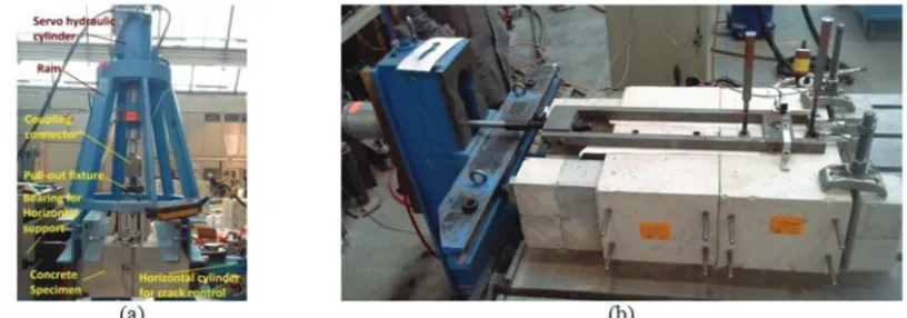
Test specimens and experimental set up
23rd Conference on Structural Mechanics in Reactor Technology Manchester, United Kingdom - August 10-14, 2015 Division V
Figure 3. Construction details of special strain-split slab specimen
Figure 4.Photographs of (a) Tension testing set up and (b) shear testing set up
TESTS AT PREDEFINED CRACK WIDTH LEVEL
These consist of monotonic tension tests, monotonic shear tests and tension cycling tests. These tests are aimed at evaluating effects of anchor load on the damage of anchorage material and anchor load deformation characteristics at given level of damage in anchorage material. Crack width at the level of effective anchorage depth is used as a measure of damage of anchorage material.
Monotonic tension tests
Figure 5. Anchor load displacement behavior obtained in monotonic tension tests on Hilti® anchor for crack width of (a) 0.0mm, (b) 0.4mm, (c) 0.8mm and (d) 1.5mm
(a) (b)
(c) (d)
Figure 6. Anchor load displacement behavior obtained in monotonic tension tests on Fischer® anchor for crack width of (a) 0.0mm, (b) 0.4mm, (c) 0.8mm and (d) 1.5mm
Tension cycling tests
23 Conference on Structural Mechanics in Reactor Technology Manchester, United Kingdom - August 10-14, 2015 Division V
load ND (30kN and 16,3kN respectively for HDA and FZA anchors). A total of 15 cycles were given.
Finally a monotonic tension pullout was carried out to evaluate the load deformation characteristics. Load deformation curves obtained for Fischer® anchor at different levels of crack widths in tension cycling tests are provided in Figure 7.
(a) (b) (c)
Figure 7. Load deformation behavior in tension cycling tests for Fischer® FZA anchor for crack width (a) 0.4mm, (b) 0.8mm and (c) 1.5mm
Monotonic shear tests
These tests are aimed at establishing anchor load deformation behavior in shear at a given damage level of the anchorage material. In each of the tests, at the predefined level of crack width, the anchor was pulled horizontally in shear at a pseudo static rate of 2mm per minute using a hydraulic cylinder. The variation of shear load against the horizontal displacement of the anchor and the failure mode was recorded in each test. The load deformation envelope obtained in monotonic shear tests with Hilti® anchor and Fischer® anchor for different level of crack width are provided in Figure 8 and Figure 9 respectively. Typical failure modes observed for Hilti® and Fischer® anchor are shown in Figure 10 and Figure 11 respectively.
(a) (b)
Figure 8. Results of monotonic shear tests on Hilti® anchor for crack width of (a) 0.0mm and (b) 1.5mm
(a) (b) (c)
(a) (b) (c)
Figure 10. Typical failure modes obtained in case of Hilti® anchor (a) steel failure in tension tests (b) pull-out and concrete cone failure in tension tests (c) steel failure observed in case of shear tests
(a) (b)
Figure 11. Typical failure modes obtained in case of Fischer® anchor (a) concrete cone failure invariably observed in all tension tests (b) steel failure observed in case of shear tests
TESTS PERFORMED WITH VARYING CRACK WIDTH
These consist of crack cycling tests at constant tension load, and simultaneous tension and crack cycling tests as explained in Table 1. Crack cycling tests at constant design tension load evaluate the effects of cycling damage of anchorage material on anchor behavior. Simultaneous tension and crack cycling tests provide information on the coupled action of load and crack cycling. For this, two extreme cases of
cycling are considered: (i) in-phase—in which load and crack are cycled at the same frequency with 0°
phase difference and (ii) out-of-phase in which load and crack are cycled at same frequency with 90° phase difference. Two ranges of crack cycling are considered: (i) corresponding to operating basis earthquake (0,5mm to 0,8mm) and (ii) corresponding to safe shutdown earthquake (1,0mm to 1,5mm). The results of the three different crack cycling tests are presented together for better comparison.
Crack cycling tests at design tension
The loading protocol of these tests is shown in Figure 12a. In the cycling phase, the anchor was loaded to level of design tension load of the anchor (16,3kN and 30kN respectively for FZA and HDA anchor). A total of 10 cycles of crack width variation in the two different ranges were performed. Finally monotonic tension pull-out was carried out to evaluate the load deformation characteristics. The load deformation behavior obtained in crack cycling tests at design tension with Hilti® anchor and Fischer® anchor for crack cycling range of 1.0mm to 1.5mm are provided in Figure 13a and Figure 14a respectively.
Out-of-phase tension and crack cycling tests
23 Conference on Structural Mechanics in Reactor Technology Manchester, United Kingdom - August 10-14, 2015 Division V
test is shown in Figure 12b. Following the cycling phase monotonic tension pull-out was carried out to evaluate the load deformation characteristics. The load deformation behavior obtained in crack cycling tests at design tension with Hilti® anchor and Fischer® anchor for crack cycling range of 1.0mm to 1.5mm are provided in Figure 13b and Figure 14b respectively.
(a) (b) (c)
Figure 12. Loading protocols for crack cycling tests (a) at design tension load (b) with out-of-phase tension load variation and (c) with in-phase tension load variation
(a) (b) (c)
Figure 13. Results of tests on Hilti® anchor with varying crack width in range 1.0mm to 1.5mm (a) at constant tension (b) out-of-phase tension and crack cycling (c) in-phase tension and crack cycling
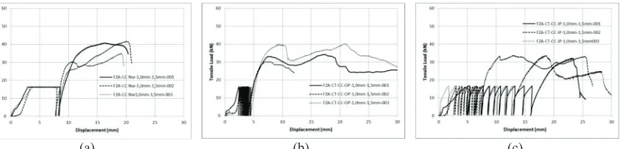
(a) (b) (c)
Figure 14. Results of tests on Fischer® anchor with varying crack width in range 1.0mm to 1.5mm (a) at constant tension (b) out-of-phase tension and crack cycling (c) in-phase tension and crack cycling
In-phase tension and crack cycling tests
CONCLUSIONS
In the present study, (i) monotonic tension and shear tests (ii) tension cycling tests at different crack widths (iii) crack cycling tests at design tension load (iv) out-of-phase tension and crack cycling tests and (v) in-phase tension and crack cycling tests, have been performed on Hilti® HDA-T-22-M12x125/30 and Fisher® FZA-18x80-M12/25 undercut anchors qualified for their use in NPPs and related structures. This experimental program was undertaken with an aim of establishing simplified inelastic models for simulating seismic behavior of anchorages for conducting structure-component interaction analyses. The scope of the present paper is limited to discussion of the results of this test program. The development of
models using the discussed tests is presented in another paper.
In the monotonic tension and shear tests at different damage levels of anchorage materials, it is observed that with increasing damage level, there is a marginal decrease in the ultimate load capacity of the Hilti® anchor and a transition of failure mode from steel failure to pullout and concrete cone failure is resulted. In case of Fischer® anchor, significant decrease in ultimate load capacity is observed with increasing damage levels and concrete cone failure was invariably observed. The monotonic pullout tests carried out after tension cycling tests and tests with varying crack widths showed that the load deformation capacity of both the anchors is retained after cycling of tension loads and crack widths.
The different crack cycling tests performed as a part of the present study conclude that behavior of anchor subjected to crack cycling tests is anchor dependent, and no generalized conclusion is possible for comparison of crack cycling tests at design tension with simultaneous tension and crack cycling tests. For Hilti® anchor, crack cycling tests at constant tension are found to be conservative in view of plastic deformation of anchors after cycling. In case of Fischer® anchor however, in-phase tension and crack cycling tests are found to be most crucial.
ACKNOWLEDGEMENTS
The presented project was funded by the German Federal Ministry of Economic Affairs and Energy (BMWi, project no. 1501450 and project no. 1501478) on basis of a decision by the German Bundestag.
REFERENCES
Antaki, G., 2000. “Seismic retrofit of critical piping systems”. Workshop on the Mitigation of Eartquake Disasters by Advanced Technolgies (MEDAT).
ASCE-4-98, 2000. Seismic analysis of safety-related nuclear structures and commentary. American
Society of Civil Engineers.
DIBt-KKW-Leitfaden, 2010. Leitfaden für Dübelbefestigungen in Kernkraftwerken und anderen
kerntechnischen Anlagen (Guideline for fastenings in nuclear power plants and other nuclear technical facilities). Deutsches Institut für Bautechnik (DIBt), Berlin (in German).
Eligehausen, R., Mallée, R., Silva, J.F., 2013. Anchorage in concrete construction. John Wiley and Sons.
ETA-98/0004, 2013. European Technical Approval ETA-98/0004 for Fischer-Zykon-Anchor FZA.
Deutsches Institut für Bautechnik, , Berlin. Valid until 20 June 2018.
ETA-99/0009, 2013. European Technical Approval ETA-99/0009 for Hilti HDA and HDA-R. Centre
Scientifique et Technique du Bâtiment, Paris. Valid until 25 March 2018.
FEMA-E-74, 2012. Reducing the Risks of Nonstructural Earthquake Damage – A Practical Guide.
Fedaral Emergency Management Agency.
23rd Conference on Structural Mechanics in Reactor Technology Manchester, United Kingdom - August 10-14, 2015 Division V
Mahrenholtz, C., 2008. “Influence of high rate loading on Hilti HDA-Test Report Part1”. Report No: AF08/02-RWE07/01, Institut für Werkstoffe im Bauwesen, Universität Stuttgart , Germany.
Sharma, A., Eligehausen, R., Hofmann, J., 2014. “Numerical Modeling of Joints Retrofitted with Haunch
Retrofit Solution”. ACI Structural Journal 111, 861–872.