Project Name _________________________________________________________________________
Supervisor Initials/Date
Originator Initials/Date Reason For Update/Comments; Associated MRs:
Type of Update
( ) Initial Release of New Document
( ) Maintenance Release to Existing Document
Date Required at Destination ______________________________________________________ First/Current Compatible System Release/Version _____________________________________ Issue/Revision, Date _____________________________________________________________ Documentation Title _____________________________________________________________
Documentation Identification ______________________________________________________
Issue 3, December 1997 SR–2275
Prepared for Bellcore by:
Information Infrastructure, Standards, and Forum Department
For further information, please contact:
A.L. Carey
J.C. Staats
Copyright © 1994, 1997 Bellcore.
SPECIAL REPORT
NOTICE OF DISCLAIMER
This Special Report is published by Bell Communications Research, Inc. (Bellcore) to inform the industry of topics discussed in Bellcore Notes on the Networks.
Bellcore reserves the right to revise this document for any reason, including but not limited to, conformity with standards promulgated by various agencies, utilization of advances in the state of the technical arts, or the reflection of changes in the design of any equipment, techniques, or procedures described or referred to herein.
BELLCORE MAKES NO REPRESENTATION OR WARRANTY, EXPRESS OR IMPLIED, WITH RESPECT TO THE SUFFICIENCY, ACCURACY, OR UTILITY OF ANY INFORMATION OR OPINION CONTAINED HEREIN. BELLCORE
EXPRESSLY ADVISES THAT ANY USE OF OR RELIANCE UPON SAID INFORMATION OR OPINION IS AT THE RISK OF THE USER AND THAT
BELLCORE SHALL NOT BE LIABLE FOR ANY DAMAGE OR INJURY INCURRED BY ANY PERSON ARISING OUT OF THE SUFFICIENCY, ACCURACY, OR UTILITY OF ANY INFORMATION OR OPINION CONTAINED HEREIN.
This document is not to be construed as a suggestion to any manufacturer to modify or change any of its products, nor does this document represent any commitment by Bellcore or any Local Exchange Carrier (LEC) or service provider to purchase any product, whether or not it provides the described characteristics.
Readers are specifically advised that each LEC may have requirements or specifications different from the generic descriptions herein. Therefore, any vendors or manufacturers of products should communicate directly with a LEC or service provider to ascertain that company's needs, specifications and actual requirements.
Nothing contained herein shall be construed as conferring by implication, estoppel or otherwise any license or right under any patent, whether or not the use of any information herein necessarily employs an invention of any existing or later issued patent.
If further information is required, please contact:
Senior Consultant Bellcore
3 Corporate Place, Room PYA 2F-241 Piscataway, NJ 08854-4199
732-699-6927
For general information about this or any other Bellcore documents, please contact:
Bellcore Customer Services 8 Corporate Place, Room 3A-184 Piscataway, NJ 08854
1-800-521-2673 (US & Canada) 732-699-5800 (all other)
732-336-2559 (FAX)
or visit
Trademark Acknowledgments
Appletalk is a registered trademark of Apple Computer, Inc.
CLASS is a service mark of Bellcore.
CLCI, CLEI, CLFI, CLLI, ISCP, NMA, SEAS,are trademarks of Bellcore.
COMMON LANGUAGE, SPACE, TELEGATE , and TIRKS are registered trademarks of
Bellcore.
DECNet is a trademark of Digital Equipment Corporation.
APPN and IBM 3270 are registered trademarks of International Business Machines
Corporation.
1/1AESS, 4ESS, 5ESS, Dataphone, and SLC are registered trademarks of Lucent
Technologies, Inc.
NEAX-61E is a trademark of NEC America, Inc.
DMS-10, DMS-100F, DATAPATH, and TOPS are trademarks of Nortel.
DMS-100 is a registered trademark of Nortel.
Bellcore Notes on the Networks
Contents
Contents
Foreword... Foreword–1
1. Overview ... 1–1
2. Local Access and Transport Areas... 2–1 2.1 LATA Design Requirements... 2–1 2.2 Design Exceptions... 2–2 2.3 LEC Relationship with Other Exchange Companies ... 2–3 2.4 LEC, Offshore, International, and Independent LATA Assignments... 2–4
3. Numbering Plan and Dialing Procedures... 3–1 3.1 NANP Number Structure ... 3–2 3.2 Numbering Plan Areas ... 3–2 3.3 Easily Recognizable Codes ... 3–3 3.4 N11 Service Codes... 3–5 3.5 Central Office Codes... 3–6 3.6 Line Numbers... 3–7 3.7 Dialing Procedures ... 3–8 3.8 Dialing Prefixes for Carrier Selection... 3–13 3.9 Operator Assistance ... 3–13 3.10 International Direct Distance Dialing ... 3–13 3.11 0XX and 1XX Codes ... 3–14 3.12 Special Characters (#) and (*)... 3–15 3.13 Vertical Service Codes ... 3–15 3.14 Automatic Number Identification II Digit Assignments... 3–16 3.15 Local Number Portability... 3–16 3.16 Number Pooling ... 3–17 3.17 Assignment of 555 Numbers... 3–17
4. Network Design and Configuration ... 4–1 4.1 Introduction ... 4–1 4.2 Operator Services Systems... 4–10 4.3 Network Design Considerations ... 4–18 4.4 Blocking Probabilities ... 4–23 4.5 LATA Network Configurations ... 4–24 4.6 Reliability of Equipment and Systems ... 4–42
5.4 Customer Network Management ... 5–11
6. Signaling ... 6–1 6.1 Introduction ... 6–1 6.2 Analog Access Line Signaling ... 6–2 6.3 Switching System Interfaces to Access Lines... 6–23 6.4 Interoffice In-Band Analog Signaling... 6–31 6.5 On- and Off-Hook Signals ... 6–35 6.6 Controlled Outpulsing ... 6–48 6.7 Loop Signaling ... 6–62 6.8 E&M Signaling ... 6–67 6.9 Duplex Signaling... 6–86 6.10 Dial Pulsing... 6–88 6.11 Single-Frequency Signaling ... 6–99 6.12 Multifrequency (MF) Signaling ... 6–110 6.13 Dual-Tone Multifrequency Signaling ...6–118 6.14 Calling Number Delivery ... 6–136 6.15 LATA Access... 6–142 6.16 Special Tandem Signaling (CAMA, OSPS, and TOPS Offices) ... 6–166 6.17 Signaling From End Offices to Operator Services Systems ... 6–173 6.18 Signaling to Automatic Intercept System ... 6–212 6.19 Carrier Group Alarm ... 6–214 6.20 Call Progress Tones (Audible Tone Signals) ... 6–218 6.21 Other Miscellaneous Signals... 6–230 6.22 Register Timing and Effect on Signaling... 6–253 6.23 Common Channel Signaling ... 6–254
7. Transmission ... 7–1 7.1 Introduction ... 7–1 7.2 Network Architecture ... 7–1 7.3 Objectives and Limits ... 7–3 7.4 Voice Transmission Impairments and their Control ... 7–5 7.5 Voiceband Data Transmission Impairments and Their Control ... 7–17 7.6 Digital Transmission ... 7–21 7.7 Digital Data Transmission... 7–24 7.8 Transmission Aspects of Switches... 7–27 7.9 Adaptive Differential Pulse-Code Modulation Technology ... 7–31 7.10 Asynchronous Transfer Mode Technology... 7–32 7.11 End-to-End Performance... 7–36 7.12 Network Transmission Design... 7–44 7.13 Operator Services Transmission ... 7–58 7.14 Transmission Limits — IntraLATA Networks ... 7–62 7.15 Loop Transmission — Design and Characterization ... 7–68 7.16 Interoperation with Other Networks ... 7–75
8.1 Introduction ... 8–1 8.2 Trunk Maintenance ... 8–2 8.3 Common Channel Signaling ... 8–29 8.4 Switch Diagnostics... 8–40 8.5 Switching System Maintenance ... 8–47 8.6 Memory Administration... 8–49 8.7 Facility Maintenance ... 8–50 8.8 Transport System Maintenance... 8–50 8.9 Loop Maintenance... 8–55 8.10 Planned Long-Term Network Advancement ... 8–57 8.11 Digital Testing Parameters ... 8–61
9. Common Systems ... 9–1 9.1 Introduction ... 9–1 9.2 Cross-Connect Systems... 9–2 9.3 Power Systems ... 9–19 9.4 Network Equipment-Building System ... 9–25
10. Surveillance and Control... 10–1 10.1 Network Traffic Management... 10–2 10.2 Network Service Center (NSC)... 10–28
11. Synchronization ... 11–1 11.1 Introduction ... 11–1 11.2 Synchronization Background ... 11–1 11.3 Hierarchical Method of Synchronization ... 11–3 11.4 Internodal Synchronization ... 11–4 11.5 Intranodal Synchronization ... 11–9 11.6 Reliability and Performance... 11–11 11.7 Interconnection with Other Networks... 11–12 11.8 Administration... 11–13 11.9 Synchronization Network Operations ... 11–14 11.10 Synchronization Network Testing... 11–15
12.12 New Technology ... 12–46
13. Terminal Equipment and Premises Wiring Interconnection... 13–1 13.1 Introduction ... 13–1 13.2 Scope ... 13–2 13.3 Terminal Equipment Connections... 13–7 13.4 Grandfather Requirements ... 13–11 13.5 Interface Specifications... 13–13 13.6 Incidence of Harm... 13–15 13.7 Compatibility Requirements ... 13–18 13.8 Testing and Maintenance ... 13–19
14. Network Architectures and Services... 14–1 14.1 Introduction ... 14–1 14.2 Common Channel Signaling ... 14–2 14.3 CLASS Services... 14–14 14.4 Service Enabling Technologies — Simplifying the User Interface ... 14–22 14.5 Line Information Database Services ... 14–29 14.6 Toll-Free Database Service ... 14–41 14.7 Advanced Intelligent Network ... 14–58 14.8 Integrated Service Control Point ... 14–71 14.9 Integrated Services Digital Network ... 14–87 14.10 Public Switched Digital Service... 14–117 14.11 Public Packet Switched Service ... 14–127 14.12 Asynchronous Transfer Mode (ATM)-Based Broadband Integrated Services
Digital Network (B-ISDN)... 14–142 14.13 Frame Relay ... 14–178 14.14 Switched Multi-megabit Data Service ... 14–184 14.15 Synchronous Optical Network ... 14–190
15. Exchange Access... 15–1 15.1 Points of Presence ... 15–1 15.2 Expanded Interconnection... 15–1 15.3 Switched-Access Service ... 15–2 15.4 Special-Access Service ... 15–12 15.5 Other Network Services ... 15–15 15.6 Interconnecting Entities ... 15–17 15.7 Transmission ... 15–18 15.8 Signaling ... 15–18 15.9 Automatic Message Accounting Measurement Requirements ... 15–19
16.5 Land-to-Mobile Calls ... 16–37 16.6 Transmission and Signaling Requirements ... 16–37 16.7 Common-Carrier Paging Systems... 16–40 16.8 FCC Part 90 Private Carriers... 16–44 16.9 CT2 Concept ... 16–45 16.10 Personal Communications Services ... 16–45
17. Open Network Architecture ... 17–1 17.1 Common ONA Model... 17–1 17.2 Basic Serving Arrangement Categories ... 17–3 17.3 Regulatory Background ... 17–21
18. Industry Forums and Standards Committees ... 18–1 18.1 Overview ... 18–1 18.2 Asynchronous Transfer Mode (ATM) Forum... 18–1 18.3 Internet Engineering Task Force (IETF)... 18–2 18.4 Intelligent Network Forum (IN Forum) ... 18–2 18.5 Digital Audio-Visual Council (DAVIC) ... 18–3 18.6 International Telecommunications Union - Telecommunications (ITU-T).. 18–3 18.7 International Telecommunications Advisory Committee -Telecommunications
(ITAC-T) ... 18–6 18.8 Telecommunications Industry Association (TIA)... 18–7 18.9 Alliance for Telecommunications Industry Solutions... 18–9
19. Interexchange Access/Local Exchange Services Ordering... 19–1 19.1 Access Service Ordering ... 19–1 19.2 Local Exchange Access Ordering ... 19–2 19.3 Access Service Ordering Guidelines (ASOG) ... 19–3 19.4 Local Service Ordering Guidelines (LSOG)... 19–7
...Glossary–1
Foreword
Preface
Bellcore Notes on the Networks, Issue 3, replaces all previous issues. The subjects discussed in this document have been updated to reflect changes in the industry since the 1994 issue of the document. Regulatory rulings, the Telecommunications Act, judicial decisions, and industry standards and forum activities have contributed to the changes.
Notes is a Special Report published by Bellcore to provide its view of technical topics related to typical LEC switched network characteristics. It is not a generic requirements document. No part of the text constitutes or suggests a requirement on the part of any LEC or entity. Attempts have been made to ensure that information contained herein is recent and reliable. However, due to the constant evolution in technology and its associated documentation, the most current information available regarding topics of interest should be sought.
Requirements and specifications for the various components that constitute LEC networks are generally contained in Bellcore generic requirements publications (GRs) or standards documents where actual requirements are clearly identified and described. Where possible, specific references have been included in this document. To adequately explain the technical attributes and operating functions of various parts of the networks, it has been necessary in some cases to refer to specific manufacturers’ equipment or systems currently in widespread use. These references do not constitute a recommendation of the specific equipment or their manufacturers by Bellcore. Throughout this document, the reader is referred to numerous sources for additional information on the topics presented.
Notes contains technical material of interest to engineering and planning groups, as well as descriptions of the characteristics and background of these subjects in layman’s terms. This issue of Notes provides an overview of some of the typical technical characteristics and basic operating principles of switched access and transport networks. New technologies, systems, and network services that have evolved since the 1994 issue and that are available and commonly deployed as of mid-year 1997 have been included. Interconnection arrangements between LECs and other entities that currently exist in some or all of the LEC switched networks are also covered. Experimental, local-application, or individual-case basis arrangements are not covered in this document.
To ensure that telecommunications entities are referred to in a manner consistent with legal, regulatory, and industry conventions, it is necessary to use a variety of terms (and
acronyms) to differentiate between types of LECs. These are explained as follows:
All LEC switched networks are composed of integrated parts that consist of transmission and switching systems, control and signaling processes, and associated operational support systems that are engineered, owned, and managed by each LEC independently. With these networks, the LECs provide, administer, and maintain telecommunications services and offer facilities arrangements to other entities that also provide telecommunications services.
These networks provide two primary functions. One function is an on-demand
communication path to connect any two customers’ points of termination within the LATA or market area. The other function is to connect these points of termination to the point of termination of another entity providing telecommunications services to its end users for the purpose of exchanging information.
Each LEC has an individual business plan that guides its deployment and operations activities, so many of the characteristics described may not apply to a particular LEC network. These plans vary greatly between companies, and obviously affect individual company purchasing and deployment decisions. Current network technology permits LECs to offer a wide variety of service offerings. These offerings vary widely from LEC to LEC, and, at times, within a particular LEC. A virtually identical service may be offered by several LECs under different names, prices, and/or arrangements. Availability and compatibility information changes almost daily. The serving LEC has the most current, detailed, and specific information about its individual offerings, deployment status, and specifications.
Joint planning between the LECs (wherever practical and appropriate) contributes to the provisioning of least-cost telecommunications services. To encourage such efforts, much of the information contained in this issue was reviewed by subject-matter experts of Bellcore, the BOCs, the United States Telephone Association (USTA), the National
LEC — Local Exchange Carrier refers to any and all exchange carriers
that provide telecommunications exchange and exchange-access service.
BOC — Bell Operating Company refers to a LEC that was part of the
former Bell System.
Independent LEC — Independent Local Exchange Carrier refers to a LEC that was not part of the former Bell System.
Telephone Cooperative Association (NTCA), and the Organization for the Protection and Advancement of Small Telephone Companies (OPASTCO).
Individual differences between LECs, the effects of state regulatory bodies, and other factors are beyond the scope and technical focus of this issue. Notes does, however, furnish much of the information needed by the telecommunications industry, regulators,
consultants, and vendors, to maintain and/or interact with the LEC networks.
Section 1
Overview
Contents
Contents
1.
Overview
Bellcore Notes on the Networks, Issue 3, is a widely recognized telecommunications primer presenting an encyclopedia-style overview of numerous technologies and topics regarding today’s Local Exchange Carrier (LEC) networks. Notes deals with complex, highly technical subjects, but presents the information in a way that makes it accessible and understandable to a variety of readers. Notes has been written with two audiences in mind; the technical and non-technical reader. While it provides sufficient detail to serve as a reference document for the technical reader, and it also was written to distill technical concepts in such a way that they are understandable to the non-technical audience.
The Table of Contents is comprehensive, and probably will be most useful to the technical reader. This is a reference document, and section titles that are useful to the technical reader may not be very useful to a non-technical reader. For that reason, this overview has been provided along with introductory material at the beginning of each section. The following paragraphs provide a very brief description of the purpose of each section. These will help guide non-technical readers to those sections of Notes that contain the needed information. Once there, introductory material in each section provides more specific information.
The last section of Notes is the Glossary, which contains acronyms, abbreviations, definitions, and symbols. The telecommunications industry, like any other highly technical and growing industry, has its own language. Any reader may, from time to time, encounter words or phrases that are not familiar, so the Glossary is included as a guide to meaning and usage. An Index has also been provided for easier access to a particular subject.
Notes is not a comprehensive document, nor is it a requirements document. Further, each LEC designs and implements its network based on its own individual business plans. Therefore, the parameters and configurations of some networks are not covered in this document. Special services, experimental services, and services not yet commonly deployed are not discussed.
Section 2 — Local Access and Transport Areas
Section 3 — Numbering Plan and Dialing Procedures
In order to be delivered, messages must be uniformly addressed via a unique telephone number and routed. The calling customer supplies much of the address, and the network adds the remainder of the address and usually defines call routing. There are many networks and geographic destinations, so standardization of the telephone numbering plan and dialing procedures is critical to ensure that telecommunication within and between networks can occur. The growth in the number of messages and the advent of Local Number Portability have necessitated expansions and changes in the numbering plan and dialing procedures, as well as the process for routing telephone calls.
Section 4 — Network Design and Configuration
Networks are configured based on a variety of economic, statistical, and other principles. Network configuration and its designed routing determines how a message travels to its destination. While most messages are dialed by the customer and handled within the LEC networks, additional entities or services (interexchange carriers or operator assistance) are available. The customer expects reliability from the telecommunications networks, which are regularly evaluated to ensure a high level of end-to-end service.
Section 5 — Billing, Custom Data, and Control
Message information is recorded, usually in the early stages of the call, for accounting, billing, or routing purposes. Customers who require additional message d etail and/or control of their network configuration can purchase LEC services (where available) that allow access to private call detail and/or customer management of limited parts of the customer network serving arrangement.
Section 6 — Signaling
Signaling refers to the sending and receiving of control information between the parts of a telecommunications network handling a message. These signals determine message status, routing, handling, control functions, billing, and access capability to other networks. Each network part must have consistent signaling protocols to handle messages within and between networks. This information is carried either on the routes or channels controlled (circuit-associated signaling), or it travels on a separate shared (common) channel used to convey this information. Due to the almost overwhelming number of potential
Section 7 — Transmission
Any message is subject to a variety of conditions that will improve or impair its
transmission. Network architecture describes the various necessary parts that provide end-to-end message connectivity. Each network part has a set of conditions to which it is vulnerable, and that must be considered as messages are passed through LEC networks.
Section 8 — Operations and Maintenance
Virtually every message must physically travel through one or more switching systems in at least one network before reaching its destination. Therefore, an effective overall maintenance plan to provide high-quality service at a reasonable cost is imperative. Because switching and support systems are closely related within and between networks, inadequate maintenance in any one system can affect any other related system. Continued automation, necessitated by the rapid growth in number and complexity of messages, requires highly evolved diagnostic and maintenance plans.
Section 9 — Common Systems
While there are many types of switching systems, there are features common to almost every type. These common systems include the building systems for the physical switch location, systems that provide power to the switching equipment, and the cross-connect systems that perform multiple functions in addition to acting as the point where the line or channel connects to the switching system.
Section 10 — Surveillance and Control
To ensure the economical use of networks and to maintain vital telecommunications services, networks are commonly equipped with surveillance and control capabilities. These capabilities allow for network traffic management, network servicing, and service evaluation. Network surveillance and control also ensure maintenance of a high level of network elements utilization, minimize the effect of network overloads, and support the LEC commitments to National Security/Emergency Preparedness (NS/EP).
Section 11 — Synchronization
Section 12 — Distribution
The distribution network is where the network connects to individual customers. In descending size order, which coincides to the order in which the facility extends from the switching system to the customer, the typical distribution network order is feeder plant, distribution plant, and the loop that connects the customer to the network. The distribution network can be composed of metallic cable, fiber-optic cable, radio, or a combination of the three, and frequently includes electronic or cross-connect equipment.
Section 13 — Terminal Equipment and Premises Wiring
Interconnection
In addition to network access via a loop, terminal equipment such as a telephone, data terminal, or private switching equipment must be connected with the Public Switched Telephone Network (PSTN). Federal Communications Commission (FCC) rules exist regarding terminal equipment manufacture, shipping tolerances, and interconnection characteristics to protect the public network from potential harm. Compatibility
requirements are specified, and respective responsibilities of the customer and the LEC are defined. This section contains general information on the FCC registration program and the demarcation point specifications.
Section 14 — Network Architectures and Services
Section 15 — Exchange Access
In most cases, LECs are precluded from providing network services that extend beyond their boundaries. Exchange access is provided to interconnecting entities (such as interexchange carriers) by LECs so that these entities can provide telecommunication services between LATAs (interLATA) to end-user customers.
Section 16 — Mobile Services Interconnection
Wireless Services Providers (WSPs) offer services using radio as their transmission medium under FCC license. WSPs require interconnection with the LEC networks, and mobile (wireless carrier) interconnection alternatives and capabilities are addressed in this section.
Section 17 — Open Network Architecture
Open Network Architecture (ONA) is a regulatory concept created by the FCC to further the FCC’s goals of bringing the full benefits of the "Information Age" to the American public. The FCC requires the LECs to offer unbundled Basic Serving Arrangements (BSAs) and Basic Service Elements (BSEs) under tariff so Enhanced Service Providers (ESPs) can access them to provide enhanced services. This section defines the elements and arrangements.
Section 18 — Industry Forums and Standards Committees
There are many industry forums, standards bodies and associations that operate in the United States and internationally that address various issues related to interconnection, technical standards, reliability and operations in the telecommunications industry. A sampling of the more prominent bodies are described in this section, including the Alliance for Telecommunications Industry Solutions (ATIS), the ATM Forum, the International Telecommunications Union, and others. Information is provided that describes the functions of the organization and it’s organizational structure, and lists contacts for further information and participation.
Section 19 — Interexchange Access/Local Exchange Access Ordering
Section 2
Local Access and Transport Areas
Contents
List of Tables
Tables
2.
Local Access and Transport Areas
As part of the divestiture of the Local Exchange Companies (LECs), the Modification of Final Judgment (MFJ) called for the separation of exchange and interexchange
telecommunications functions. Exchange services can be provided by LECs; interexchange services are to be provided by other than LEC entities.
New service territories called Local Access and Transport Areas (LATAs), also referred to as service areas by some LECs, were created in response to the MFJ exchange-area requirements. LATAs serve the following two basic purposes:
•They provide a method for delineating the area within which the LECs may offer services
•They provided a basis for determining how the assets of the former Bell System were to be divided between the LECs and AT&T at divestiture.
Appendix B of the MFJ requires each LEC to offer equal access through LEC end offices in a LATA to all Interexchange Carriers (ICs). All carriers must be provided services that are equal in type, quality, and price to those provided to AT&T. In general, such services include, but are not limited to, providing network-control signaling, answer supervision, automatic calling-number identification, Carrier Access Codes (CACs), directory services, testing and maintenance of facilities, and billing data.
2.1
LATA Design Requirements
The MFJ, Section IV, 9.1-4, contains specific guidelines for the establishment of LATAs. These Court-approved requirements are listed below.
•Any area may encompass one or more contiguous local exchanges serving common social, economic, and other purposes — even where such configuration transcends municipal or other local-government boundaries.
•Every point served by a LEC within a state will be included within an exchange area. Any area that includes part or all of one Standard Metropolitan Statistical Area (SMSA),1 or a Standard Consolidated Statistical Area (SCSA) in the case of densely populated states, needs Court approval to include a substantial part of any other SMSA or SCSA.
•Except with Court approval, no exchange area located in one state may include any point located within another state.
SMSAs became the new basis for LEC service areas. A large-population nucleus (for example, a city) and its adjacent communities have a high degree of economic and social integration and, therefore, have a need to communicate with each other. SMSAs provide the boundaries within which federal agencies compile information on population, housing, industry, trade, employment, and a wide range of other subjects. SCSAs are combinations of two or more related SMSAs.
SMSAs are designated and defined according to published specifications. Under current guidelines, an area qualifies for recognition as an SMSA if it contains a city of at least 50,000 people, or if it contains an urbanized area with a population of 50,000 that is part of a total metropolitan-area population of at least 100,000. The federal government had previously designated a total of 323 SMSAs nationwide, and 50 of the SMSAs were combined to form 17 SCSAs. As a result of the latest review process, both the number of and terminology for statistical areas have changed.
On June 30, 1990, there were 263 Metropolitan Statistical Areas (MSAs) and 20 Consolidated Metropolitan Statistical Areas (CMSAs). These are roughly equivalent to SMSAs and SCSAs, respectively. However, CMSAs are composed of 71 areas called Primary Metropolitan Statistical Areas. LECs are the predominant service providers in 220 of the MSAs and 17 of the CMSAs. But in some cases (for example, Los Angeles), other LECs also serve significant numbers of subscribers.
Several characteristics of MSAs have an impact on LATA design. By definition, MSAs designate only metropolitan areas, and therefore do not cover all areas served by the LECs. MSAs are sometimes contiguous, making the identification of separate communities-of-interest difficult from a telecommunications perspective. MSAs follow county boundaries that frequently do not coincide with local exchange or wire center boundaries. For these and other reasons, LATAs do not directly overlay MSAs. However, the MFJ relies heavily on the use of MSAs in the configuration of LATAs. There are several reasons for this:
•MSAs were defined by the federal government
•MSAs have become a widely accepted method of defining meaningful population groups
•Using MSAs allows areas with a high community-of-interest to remain intact.
Based on the guidelines provided by the MFJ, the LECs designed LATAs to encompass all areas now served by the LECs. Tables 2-1 through 2-7 list the 164 LEC LATAs approved by the Court.
2.2
Design Exceptions
Economic factors and customer considerations determined the type of exception requested. Specific exceptions were granted where the Court was convinced that there were
compelling economic or service reasons. In most cases, permanent exceptions from MFJ guidelines were requested and approved. In other cases, the exceptions applied for were temporary in nature.
Generally, permanent exceptions were sought where LATA configurations, if forced into MFJ guidelines, would have created negative social and economic consequences. In each case, care was taken to ensure that the exceptions did not contradict the spirit and purpose of the MFJ. Exceptions were requested to accomplish the following:
•Continue existing service arrangements such as flat-rate, Extended-Area Service (EAS), and privileged-business
•Include nonsubstantial markets
•Preserve existing wire center boundaries
•Preserve existing communities-of-interest
•Minimize disruption to end office toll trunking
•Minimize impact on customers
•Include a tandem arrangement.
Permanent exceptions were requested for LATAs that did not fully meet the boundary requirements contained in Section 2.1, and LATAs were approved with boundaries crossing state lines and containing substantial parts of more than one MSA/CMSA. Some LATAs required exceptions for both reasons.
In some instances, exceptions were requested to permit the LECs to provide certain types of interLATA services. Permission to continue existing long-standing LEC local-calling arrangements and EAS across LATA boundaries were granted by the Court. In addition, limited corridor exceptions were required to preserve traditional direct LEC interstate serving arrangements. These exceptions called for LEC-to-LEC, interLATA trunking between, for example, portions of the New Jersey LATAs, and between portions of the Philadelphia LATA and portions of the Delaware Valley (NJ) LATA.
A number of LATAs were approved that contained one MSA/CMSA and a nonsubstantial part of another MSA/CMSA. No exceptions were required in these cases.
2.3
LEC Relationship with Other Exchange Companies
Communications Commission (FCC) rules, independent LECs are also required to provide equal access upon receipt of a bona fide request, when that request does not present an undue implementation burden to the independent LEC.
Analysis of traffic between independent LEC-served areas and LEC LATAs was necessary to determine the nature of the traffic (interLATA versus intraLATA) for the purpose of asset assignment, and to clearly delineate the areas the LECs could serve. The Department of Justice (DOJ) defined the proper approach under the decree as, in general, treating the territory served by an independent company as if it were served by a LEC. Thus, if the traffic or facility arrangement would not violate the decree if the territory at issue were served by a LEC, it would not be deemed in violation of the decree by the DOJ if served by an independent company. In addition, guidelines to assist in the classification of traffic were also provided by the DOJ.
The Court has approved the associations of independent LEC exchanges as proposed by the LECs and modified by the DOJ. However, because the independent LECs and LECs must negotiate the business arrangements needed to implement the association, changes can result. In the future, a LEC can petition the Court for a revised classification of particular LEC/independent LEC traffic.
2.4
LEC, Offshore, International, and Independent LATA
Assignments
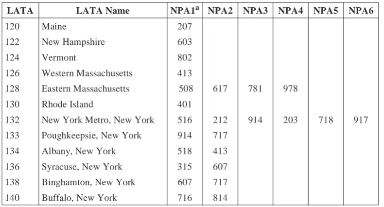
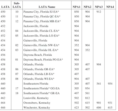
Tables 2-1 through 2-9 provide the LATA assignments for LECs, offshore and international companies, and independent companies. These assignments are also
a. An NPA is a specific geographical area identified by a unique NPA code. The boundaries of an NPA code are normally within a state, province, or subdivision of another country within the North American Numbering Plan (NANP).
Table 2-1. Numerical LATA Assignments — NYNEX
LATA LATA Name NPA1a NPA2 NPA3 NPA4 NPA5 NPA6
120 Maine 207
122 New Hampshire 603
124 Vermont 802
126 Western Massachusetts 413
128 Eastern Massachusetts 508 617 781 978
130 Rhode Island 401
132 New York Metro, New York 516 212 914 203 718 917
133 Poughkeepsie, New York 914 717
134 Albany, New York 518 413
136 Syracuse, New York 315 607
138 Binghamton, New York 607 717
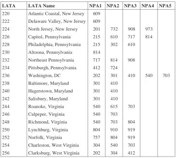
Table 2-2. Numerical LATA Assignments — Bell Atlantic
LATA LATA Name NPA1 NPA2 NPA3 NPA4 NPA5
220 Atlantic Coastal, New Jersey 609 222 Delaware Valley, New Jersey 609
224 North Jersey, New Jersey 201 732 908 973
226 Capitol, Pennsylvania 215 610 717 814
228 Philadelphia, Pennsylvania 215 302 610
230 Altoona, Pennsylvania 814
232 Northeast Pennsylvania 717 814 908
234 Pittsburgh, Pennsylvania 412 724
236 Washington, DC 202 301 410 540 703
238 Baltimore, Maryland 301 410
240 Hagerstown, Maryland 301 410
242 Salisbury, Maryland 301 410
244 Roanoke, Virginia 540 615 703
246 Culpeper, Virginia 540 703
248 Richmond, Virginia 540 703 804
250 Lynchburg, Virginia 804 910 919
252 Norfolk, Virginia 757 804 919
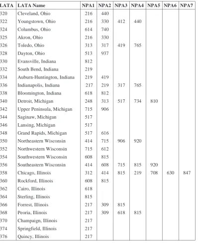
Table 2-3. Numerical LATA Assignments — Ameritech
LATA LATA Name NPA1 NPA2 NPA3 NPA4 NPA5 NPA6 NPA7
320 Cleveland, Ohio 216 440
322 Youngstown, Ohio 216 330 412 440
324 Columbus, Ohio 614 740
325 Akron, Ohio 216 330
326 Toledo, Ohio 313 317 419 765
328 Dayton, Ohio 513 937
330 Evansville, Indiana 812
332 South Bend, Indiana 219
334 Auburn-Huntington, Indiana 219 419
336 Indianapolis, Indiana 217 219 317 765
338 Bloomington, Indiana 618 812
340 Detroit, Michigan 248 313 517 734 810
342 Upper Peninsula, Michigan 715 906
344 Saginaw, Michigan 517
346 Lansing, Michigan 517
348 Grand Rapids, Michigan 517 616
350 Northeastern Wisconsin 414 715 906 920
352 Northwestern Wisconsin 715 612 354 Southwestern Wisconsin 608 815
356 Southeastern Wisconsin 414 608 715 815 920
358 Chicago, Illinois 312 414 815 219 708 630 847
360 Rockford, Illinois 608 815
362 Cairo, Illinois 618
364 Sterling, Illinois 815
366 Forrest, Illinois 217 309 815
368 Peoria, Illinois 217 309 618 815
370 Champaign, Illinois 217
374 Springfield, Illinois 217
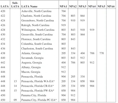
Table 2-4. Numerical LATA Assignments — BellSouth
LATA
Sub-LATA Sub-LATA Name NPA1 NPA2 NPA3 NPA4 NPA5 NPA6
420 Asheville, North Carolina 704
422 Charlotte, North Carolina 704 803 864
424 Greensboro, North Carolina 704 910 919
426 Raleigh, North Carolina 919
428 Wilmington, North Carolina 803 843 910 919
430 Greenville, South Carolina 704 803 864
432 Florence, South Carolina 803 843
434 Columbia, South Carolina 803
436 Charleston, South Carolina 803 843
438 Atlanta, Georgia 205 334 404 706 770
440 Savannah, Georgia 803 843 912
442 Augusta, Georgia 404 706 803 912
444 Albany, Georgia 912
446 Macon, Georgia 912
448 Pensacola, Florida 904 205 334
448 13 Pensacola, Florida WA-EA* 205 334 850 904
448 14 Pensacola, Florida CR-EA* 205 334 850 904
448 15 Pensacola, Florida FW-EA* 850 904
450 Panama City, Florida 904 912
450 09 Panama City, Florida PC-EA* 850 904
Table 2-4. Numerical LATA Assignments — BellSouth (Continued)
LATA
Sub-LATA LATA Name NPA1 NPA2 NPA3 NPA4
450 10 Panama City, Florida SJ-EA* 850 904 912
450 11 Panama City, Florida QC-EA* 850 904
450 12 Panama City, Florida MR-EA* 850 904
452 Jacksonville, Florida 904
452 04 Jacksonville, Florida CL-EA* 904 452 05 Jacksonville, Florida LO-EA* 904
454 Gainesville, Florida 904
454 02 Gainesville, Florida NW-EA* 352 904
454 03 Gainesville, Florida OL-EA* 904 352
456 Daytona Beach, Florida 904
456 01 Daytona Beach, Florida PO-EA* 904
458 Orlando, Florida 305 407 904
458 06 Orlando, Florida OR-EA* 305 407
458 07 Orlando, Florida LB-EA* 407
458 08 Orlando, Florida WI-EA* 904 407
460 Southeastern Florida 305 407 561 954
460 17 Southeastern Florida* GG-EA 305 954
460 18 Southeastern Florida* GR-EA 407 561
462 Louisville, Kentucky 502 812
464 Owensboro, Kentucky 502 615 901 931
466 Winchester, Kentucky 423 502 606 615
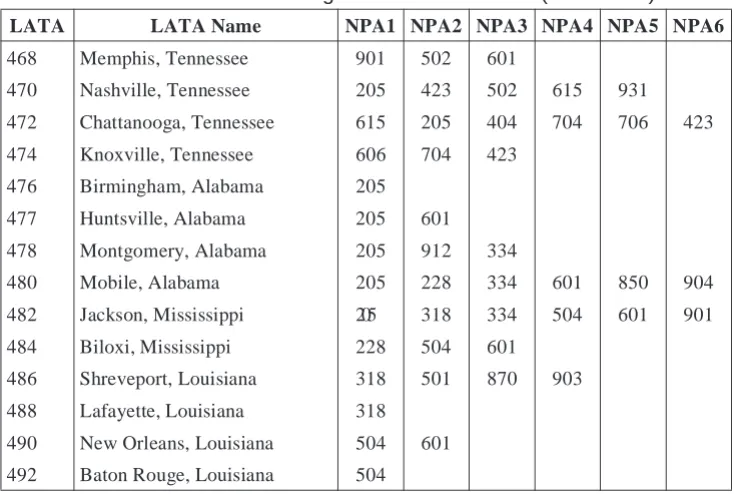
Table 2-4. Numerical LATA Assignments — BellSouth (Continued)
LATA LATA Name NPA1 NPA2 NPA3 NPA4 NPA5 NPA6
468 Memphis, Tennessee 901 502 601
470 Nashville, Tennessee 205 423 502 615 931
472 Chattanooga, Tennessee 615 205 404 704 706 423
474 Knoxville, Tennessee 606 704 423
476 Birmingham, Alabama 205
477 Huntsville, Alabama 205 601
478 Montgomery, Alabama 205 912 334
480 Mobile, Alabama 205 228 334 601 850 904
482 Jackson, Mississippi 205 318 334 504 601 901
484 Biloxi, Mississippi 228 504 601
486 Shreveport, Louisiana 318 501 870 903
488 Lafayette, Louisiana 318
Table 2-5. Numerical LATA Assignments — Southwestern Bell Telephone
LATA LATA Name NPA1 NPA2 NPA3 NPA4 NPA5 NPA6 NPA7
520 St. Louis, Missouri 314 573 618
521 Westphalia, Missouri 314 573
522 Springfield, Missouri 316 417 501 870 918
524 Kansas City, Missouri 417 660 712 785 816 913
526 Fort Smith, Arkansas 501 417 918
528 Little Rock, Arkansas 314 501 573 870 918
530 Pine Bluff, Arkansas 318 501 870
532 Wichita, Kansas 316 405 417 719 918
534 Topeka, Kansas 303 308 402 785 913
536 Oklahoma City, Oklahoma 405 806
538 Tulsa, Oklahoma 316 918
540 El Paso, Texas 505 915
542 Midland, Texas 915
544 Lubbock, Texas 806
546 Amarillo, Texas 405 505 719 806
548 Wichita Falls, Texas 817 940
550 Abilene, Texas 915
552 Dallas, Texas 214 254 817 903 940 972
554 Longview, Texas 214 501 870 903 972
556 Waco, Texas 254 817
558 Austin, Texas 512
560 Houston, Texas 281 409 713
562 Beaumont, Texas 409
564 Corpus Christi, Texas 512
566 San Antonio, Texas 210 512 830 956
568 Brownsville, Texas 210 830 956
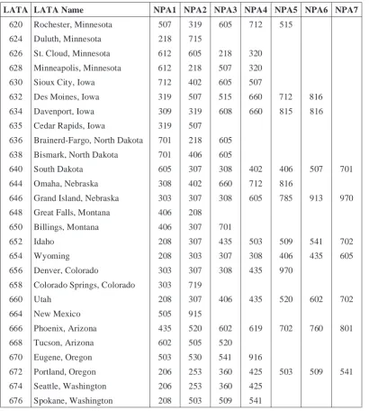
Table 2-6. Numerical LATA Assignments — U S WEST
LATA LATA Name NPA1 NPA2 NPA3 NPA4 NPA5 NPA6 NPA7
620 Rochester, Minnesota 507 319 605 712 515
624 Duluth, Minnesota 218 715
626 St. Cloud, Minnesota 612 605 218 320
628 Minneapolis, Minnesota 612 218 507 320
630 Sioux City, Iowa 712 402 605 507
632 Des Moines, Iowa 319 507 515 660 712 816
634 Davenport, Iowa 309 319 608 660 815 816
635 Cedar Rapids, Iowa 319 507
636 Brainerd-Fargo, North Dakota 701 218 605
638 Bismark, North Dakota 701 406 605
640 South Dakota 605 307 308 402 406 507 701
644 Omaha, Nebraska 308 402 660 712 816
646 Grand Island, Nebraska 303 307 308 605 785 913 970
648 Great Falls, Montana 406 208
650 Billings, Montana 406 307 701
652 Idaho 208 307 435 503 509 541 702
654 Wyoming 208 303 307 308 406 435 605
656 Denver, Colorado 303 307 308 435 970
658 Colorado Springs, Colorado 303 719
660 Utah 208 307 406 435 520 602 702
664 New Mexico 505 915
666 Phoenix, Arizona 435 520 602 619 702 760 801
668 Tucson, Arizona 602 505 520
670 Eugene, Oregon 503 530 541 916
672 Portland, Oregon 206 253 360 425 503 509 541
674 Seattle, Washington 206 253 360 425
Table 2-7. Numerical LATA Assignments — Pacific Bell
LATA LATA Name NPA1 NPA2 NPA3 NPA4 NPA5 NPA6 NPA7
720 Reno, Nevada 530 541 702 916
721 Pahrump, Nevada 702
722 San Francisco, California 408 415 510 650 707
724 Chico, California 530 916
726 Sacramento, California 530 707 916
728 Fresno, California 209
730 Los Angeles, California 213 310 520 562 602 619 626
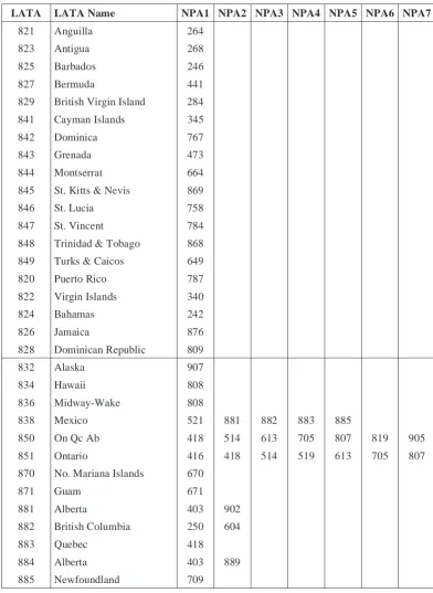
Table 2-8. Numerical LATA Assignments — Others
LATA LATA Name NPA1 NPA2 NPA3 NPA4 NPA5 NPA6 NPA7
821 Anguilla 264
823 Antigua 268
825 Barbados 246
827 Bermuda 441
829 British Virgin Island 284
841 Cayman Islands 345
842 Dominica 767
843 Grenada 473
844 Montserrat 664
845 St. Kitts & Nevis 869
846 St. Lucia 758
847 St. Vincent 784
848 Trinidad & Tobago 868 849 Turks & Caicos 649
820 Puerto Rico 787
822 Virgin Islands 340
824 Bahamas 242
826 Jamaica 876
828 Dominican Republic 809
832 Alaska 907
834 Hawaii 808
836 Midway-Wake 808
838 Mexico 521 881 882 883 885
850 On Qc Ab 418 514 613 705 807 819 905
851 Ontario 416 418 514 519 613 705 807
870 No. Mariana Islands 670
871 Guam 671
881 Alberta 403 902
882 British Columbia 250 604
883 Quebec 418
884 Alberta 403 889
886 British Columbia 250 403 604 887 NS & Prince Ed Island 902
888 Manitoba 204
889 NS & Prince Ed Island 902
890 New Brunswick 506
891 Saskatchewan 306
892 Ab & YT 250 403 604 819 867 889
Table 2-8. Numerical LATA Assignments — Others
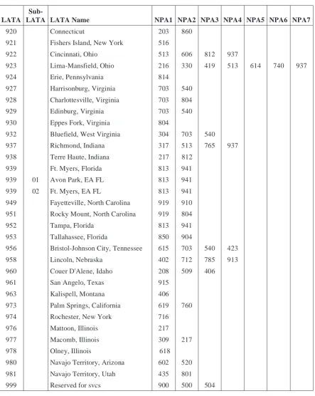
Table 2-9. Numerical LATA Assignments — Independents
LATA
Sub-LATA Sub-LATA Name NPA1 NPA2 NPA3 NPA4 NPA5 NPA6 NPA7
920 Connecticut 203 860
921 Fishers Island, New York 516
922 Cincinnati, Ohio 513 606 812 937
923 Lima-Mansfield, Ohio 216 330 419 513 614 740 937
924 Erie, Pennsylvania 814
927 Harrisonburg, Virginia 703 540
928 Charlottesville, Virginia 703 804
929 Edinburg, Virginia 703 540
930 Eppes Fork, Virginia 804
932 Bluefield, West Virginia 304 703 540
937 Richmond, Indiana 317 513 765 937
938 Terre Haute, Indiana 217 812
939 Ft. Myers, Florida 813 941
939 01 Avon Park, EA FL 813 941
939 02 Ft. Myers, EA FL 813 941
949 Fayetteville, North Carolina 919 910 951 Rocky Mount, North Carolina 919 804
952 Tampa, Florida 813 941
953 Tallahassee, Florida 850 904
956 Bristol-Johnson City, Tennessee 615 703 540 423
958 Lincoln, Nebraska 402 712 785 913
960 Couer D'Alene, Idaho 208 509 406
961 San Angelo, Texas 915
963 Kalispell, Montana 406
973 Palm Springs, California 619 760
974 Rochester, New York 716
976 Mattoon, Illinois 217
977 Macomb, Illinois 309 217
978 Olney, Illinois 618
980 Navajo Territory, Arizona 602 520
981 Navajo Territory, Utah 435 801
Section 3
Numbering Plan and
Dialing Procedures
Contents
List of Figures
Figures
Figure 3-1. International Telephone Number Format ... 3–1
List of Tables
Tables
Table 3-1. NANP Telephone Number Format... 3–2 Table 3-2. Service Code Assignments ... 3–5 Table 3-3. Major Dialing Options... 3–8 Table 3-4. Recommended Dialing Procedure for Directory Assistance
Under Feature Group D ...3–10 Table 3-5. Treatment of 0 and 00 Dialed Calls from Equal-Access End
3.
Numbering Plan and Dialing Procedures
All domestic telecommunications numbering plans for public networks conform to the major aspects of standards established by the International Telecommunication Union— Telecommunication Standardization Sector (ITU-T).1 Recommendation E.164, revised in 1977, defines international telephone numbers to be in the format shown in Figure 3-1.
Country codes, which may be 1, 2, or 3 digits in length, are assigned by the ITU-T and reported in an annex to Recommendation E.164. Within the geographic area designated for each country code, the local administration may define its own national numbering plan. The combined length of the country code and national (significant) number cannot exceed 15 digits.
Country code “1” is shared by 18 countries in North America. Within this area, national numbers are formatted according to the North American Numbering Plan (NANP).
1. Formerly the International Telegraph and Telephone Consultative Committee (CCITT).
Figure 3-1. International Telephone Number Format 1 to 3 Digits
Maximum of 15 Digits
3.1
NANP Number Structure
The NANP is based on a destination code principle where each main telephone in the NANP has a specific address assigned to it. NANP numbers are in the 10-digit functional format shown in Table 3-1.
NANP numbers may be geographic or non-geographic. Geographic NANP numbers define a hierarchy. The area served by the NANP is divided into distinct geographic areas, called Numbering Plan Areas (NPAs), each of which is assigned a NPA code.
Certain NPA codes identify services rather than geographic areas. The functions of these non-geographic codes are explained in Sections 3.3 and 3.4 below.
Central office (NXX) codes are typically assigned to switching entities/points of interconnection that provide basic switching functions within each NPA. Each central office code can serve as many as 10,000 subscriber lines or station numbers. The
subsections that follow describe NPAs, central office codes, and station numbers in more detail.
3.2
Numbering Plan Areas
Most NPA codes, also called area codes, identify a geographic area. Tables 3-7 and 3-8 at the end of this section list the NPA codes assigned through September 1997. Updated assignment data is available from the NANP administrator.
3.2.1 NPA Code Format and Capacity
NPA codes are in the following format.
NXX
where N is any digit 2 through 9 X is any digit 0 through 9.
Table 3-1. NANP Telephone Number Format
3-Digit Numbering Plan Area (NPA) Code
+
3-Digit Central Office Code
+
This NXX format provides a total of 792 NPA codes, calculated as follows:
3.2.2 NPA Code Assignment
NPA codes are assigned by the NANP administrator in accordance with guidelines developed by the Industry Numbering Committee (INC). The document is entitled INC 96-0308-011, NPA Allocation Plan and Assignment Guidelines. Documents developed and maintained by the INC may be downloaded from the home page of the Alliance for Telecommunications Industry Solutions (ATIS) at www.atis.org.
NPAs were created and designed in ways that maximize caller understanding while minimizing both dialing effort and equipment cost. There are several principles to be considered in planning NPA boundary changes due to either the introduction of new NPAs or the realignment of existing NPA boundaries. These principles are included in
INC 97-0404-016, NPA Code Relief Planning and Notification Guidelines.
3.3
Easily Recognizable Codes
NPA codes in the format NZZ, where ZZ = 00, 22, 33, … 88 are called Easily Recognizable Codes (ERCs). These non-geographic codes are reserved and allocated to provide caller access to specific services. Currently assigned ERCs include 500, 600, 700, 800, 877, 888, and 900.
Numbers in the 500 ERC are used for “follow-me” personal communications services. These services are defined in document INC-95-0407-009, Personal Communications Services N00 NXX Code Assignment Guidelines, which also explains how these codes are administered.
The 600 ERC is a mixed service code uniquely for Canada. The 600 ERC is administered by the Canadian Number Administrator in conjunction with the Canadian Steering Committee on Numbering (CSCN). 600-NXX codes are available to any Canadian carrier that meets assignment criteria established by the CSCN.
The entire range of central office codes and line numbers associated with the 700 ERC has been assigned for unrestricted use by Interexchange Carriers (ICs) to provide network-based services. Each IC has access to the full complement of codes and numbers within the 700 ERC. Therefore, these codes and numbers are not centrally administered.
Maximum NPA codes available with NXX format (8*10*10) 800
Less reserved codes of N11 format (see Section 3.4) 8
Telephone numbers within the 800, 888, and 877 ERCs are used to provide a service - freephone - in which the called party, rather than the calling party, is charged for the call. Since May 1, 1993, Service Provider Portability (SPP) has been mandatory for these numbers in the United States and its territories, and now in Canada as well. End users interested in obtaining an 800, 888, or 877 number can contact one of the many responsible organizations that have access to the Service Management System (SMS/800) for number assignment.
Telephone numbers within the 900 ERC are used to provide various special services - premium rate - to callers. Information services, polling, and fund-raising are among the many services provided. Typically these services involve call charges established by each 900 service provided to the caller. Following industry-developed guidelines documented in INC 97-0404-012, 900 NXX Code Assignment Guidelines, the NANP administrator assigns 900 NXX codes to common carriers who wish to provide such services to the public. A list of currently assigned 900 NXX codes may be obtained from the NANP administrator or from Volume 8, Section 4.9 of the Local Exchange Routing Guide (LERG), TR-EOP-000092. The LERG contains information about local routing data obtained from the Routing Database System (RDBS). This information reflects the current network configuration and scheduled network changes for all entities originating or terminating within the NANP, excluding Canada. For more information on the LERG, contact Bellcore Traffic Routing Administration at 732-699-6700.
A few NPA codes not in ERC format have also been assigned to designate non-geographic services. These codes include 456, 710, 880, and 881.
Numbers in the 456 NPA are used to identify specific carrier networks on calls placed from outside the area served by the NANP and terminating inside a NANP country, or calls from one NANP country to another, but not within a NANP country. These numbers are described in document INC-94-0826-003.
Numbers in the 710 NPA are used by the U.S. Government for purposes of national security and emergency preparedness. More information can be found in Bellcore Letter IL-94-01-002.
Numbers in the 880 and 881 NPAs are used to provide foreign-billed 800-type service, i.e., calls originating from one NANP country and terminating in another NANP country, for which the international portion of the call is paid for by the caller, and the terminating domestic portion of the call is free to the calling party. Numbers in the 880 NPA correspond to numbers in the 800 NPA, and numbers in the 881 NPA correspond to numbers in the 888 NPA. Further details are in Bellcore Letter IL-96-03-001.
3.3.1 Media Representation of Easily Recognizable Codes
parentheses imply that dialing the code is optional. Media advertising that includes ERCs should show them preceded by the prefix digit “1” (for example, 1+ 800 + NXX-XXXX).
3.4
N11 Service Codes
Service codes serve various special functions. Some are no longer in use, others are in limited use, and some are standard almost everywhere. Table 3-2 shows service code assignments currently used in many LEC networks. These codes are not available for assignment as geographic NPA codes nor as ERCs.
3.4.1 Unassigned Service Codes
Any unassigned service codes that are phased out of service, including 611 and 811, will be kept available for future assignment by the NANP administrator. Service codes may be used locally if their assignment and use can be discontinued on short notice.
3.4.2 Universal Emergency Number
Where it has been implemented, public emergency service should be universally accessible by dialing 911. A requirement for callers to dial a 1 (or any other) prefix with the digits 911 is strongly discouraged. Enhanced 911 service should not be referred to or shown as “E911” to avoid the possible misconception that the “E” could or should be dialed. Enhanced 911 service differs from 911 in that with Enhanced 911 the telephone number and the location (address) of the caller are available to the emergency center.
Table 3-2. Service Code Assignments
Code Assignment
211 Unassigned
311 Non-Emergency Access to Police, etc. 411 Local Directory Assistance
511 Unassigned
611 Telco Repair Service
711 Telecom Relay Service 811 Telco Business Office
3.4.3 N99 Codes
NPA codes in the format N99 are reserved for potential use in the future expansion of the three-digit NPA code format. The INC is studying both the potential for expansion and the need for these codes to support the transition to the expanded format.
3.5
Central Office Codes
This section describes central office codes.
3.5.1 Central Office Code Format and Capacity
Central office codes are in the following format.
NXX
where N is any digit 2 through 9, and X is any digit 0 through 9.
This NXX format provides a total of 792 central office codes.
3.5.2 Central Office Code Assignments
Central office code assignments are made in accordance with the document INC 95-0407-008, Central Office Code (NXX) Assignment Guidelines.
3.5.3 Code Conservation and Relief
The continuing growth in telephone number assignments has made code conservation and code relief an important consideration. Central office code conservation is discussed in Section 8 of the above-referenced assignment guidelines. Relief planning principles are discussed in INC 97-0404-016, NPA Code Relief Planning and Notification Guidelines.
Central office codes available in NXX format 800
Less reserved codes in N11 format 8
3.6
Line Numbers
3.6.1 Line Number Format and Capacity
Line numbers are in the following format.
XXXX
where X is any digit 0 through 9.
3.6.2 Line Number Assignments
Telephone number assignments are outside the scope of this document. However, in the absence of specific line number assignment guidelines, the following are specific considerations for such assignments.
Some patterns of dialing irregularities, coupled with the existence of various high-volume numbers (for example, NPA-555-1212), can lead to large quantities of wrong number calls being directed toward certain station numbers in the Direct Distance Dialing (DDD) network. Wrong numbers due to dialing mistakes, when spread randomly through the network, are largely unavoidable but tolerable to most customers who receive an occasional “wrong number” call. However, when high-volume numbers are involved, even a very small dialing error rate can result in a significant volume of wrong numbers being directed to a few customers. Such a situation can be intolerable to the recipients. Therefore, it is appropriate to take steps to avoid such situations.
The following are some of the known dialing irregularities.
a. Dialing that starts before dial tone is received results in the loss of Dual-Tone
Multifrequency (DTMF) dialed digit(s) or the first few pulses (digits) of a dial-pulsed (rotary dialed) call. Slow dial tone aggravates this irregularity.
b. Omitting the prefix digit “1” when required preceding a 10-digit call.
c. Dialing one digit too high or too low anywhere in the call address. This is generally more prevalent with rotary dials than with touch-tone dialing.
d. Omitting the 800 or 888 ERC when customers know that the call terminates in their own NPA.
To avoid problems resulting from these irregularities, the following guidelines are recommended.
•Leave the numbers NX5-5512 unassigned. This prevents error (b).
•Any central office using codes 255, 355, or 455 should leave station number 1212 unassigned. This is to guard against error (a) in the rotary dial case. The assumption is that once a caller places a finger in the wrong position on the dial he/she will dial all three central office code digits without removing the dialing finger each time. Similar logic could be applied to 222-, 444-, 666- and 888-1212 for touch-tone dialing, but such errors seem less prevalent than the rotary dial case.
•Any central office using a code in the form N91 should avoid placing subscribers who are likely to receive a high volume of calls in the N91-1XXX station number to prevent misdialing to 911. This prevents error (a).
3.6.3 Coin Station Numbering
It has been recommended that public and semipublic stations be assigned line numbers in the 9000 series (for example, NXX-9XXX). Generally, current operating practices include a check for public/semipublic telephones on collect or third-number calls to 9000 series numbers only.
Many public/semipublic telephones meet the requirements for an automated check. In those cases where the automated public/semipublic station check can be applied, there is no need to have the called public station numbered in the 9XXX series.
However, there are still many situations in which the 9XXX line number is the only indication of a public/semipublic station. Therefore, it is still suggested that companies assign public/semipublic stations in this 9XXX line number series when possible.
3.7
Dialing Procedures
Dialing refers to the use of certain digits or special characters as prefixes or appendixes to the number address as defined by the NANP. In the U.S., dialing is regulated by local public utility commissions, and as a result, dialing patterns vary from one jurisdiction to another. For example, the digit “1” is used in the NANP to indicate that the full 10-digit NANP number will follow. The prefix “1” is also used in many areas of the NANP to indicate that a call within the “home” NPA will incur a toll charge. In such a use, the “1” is part of the dialing plan. Table 3-3 illustrates the major dialing options in use.
Table 3-3. Major Dialing Options
Option I Option II Option III
Local call within home NPA 7 digits 7 digits 7 digits
Toll call within home NPA 7 digits 1 + 10 digits 1 + 10 digits
In all options, 7-digit local calling is permitted for calls within the home NPA, except in areas where NPA overlays have been implemented. In these areas, all calls must be dialed on a 10-digit basis as directed by the FCC in its Second Report and Order in CC Docket 96-98.
Several different dialing arrangements are in use for local calls that cross NPA boundaries. In some locations these calls may be dialed on a 10-digit basis, without the prefix “1.” In other locations, 7-digit dialing to foreign NPAs is retained through the use of “protected” NXX codes. The use of protected codes is discouraged because it uses central office codes inefficiently and may contribute to the premature exhaust of an NPA.
Because dialing patterns vary in the NANP, the industry felt it was important to develop and recommend a uniform dialing plan. The resulting document, INC 97-0131-017, Industry Numbering Committee Uniform Dialing Plan, recommends that all calls be dialed on a uniform 10-digit basis, eliminating the use of the prefix “1” as a toll indicator. If required, however, toll indication could be provided in another manner such as a tone indicating that the caller will incur additional charges. Although the industry has made its recommendation, no decisions have been made on implementation.
Table 3-4. Recommended Dialing Procedure for Directory Assistance Under
Feature Group D
Type of Call Dialing Procedure Operator Reached IntraLATA HNPA* FNPA
411 or 555-1212 1+ NPA-555-1212 LEC LEC HNPA** FNPA** 101XXXX-555-1212 101XXXX-1+NPA-555-1212 IntraLATA Carrier IntraLATA Carrier InterLATA HNPA* FNPA 555-1212
1 + NPA-555-1212
LEC IC† HNPA FNPA 101XXXX-555-1212 101XXXX-1+NPA-555-1212 IC† IC† Legend: FNPA HNPA IC LATA LEC NPA = = = = = =
Foreign Numbering Plan Area Home Numbering Plan Area Interexchange Carrier
Local Access and Transport Area Local Exchange Carrier
Numbering Plan Area *
**
†
Use of the prefix 1 is acceptable in areas where Centralized Automatic Message Accounting (CAMA) access is required.
Only applies in those areas where intraLATA competition is allowed.
Table 3-5. Treatment of 0 and 00 Dialed Calls from Equal-Access End
Offices
Dialing Format Suggested Disposition Equal-Access End Office
0
00
101XXXX + 0
101XXXX + 00
101XXXX + 0+7/10D
00 + 7/10D
LEC
IC*
IC
IC**
IntraLATA - IC, if permitted†
IntraLATA - LEC‡ IntraLATA - IC‡
Legend: IC LATA LEC X D = = = = = Interexchange Carrier
Local Access and Transport Area Local Exchange Carrier
Any digit 0 through 9 Digits
*
**
†
‡
Assumes subscriber is presubscribed.
While this is not a NANP dialing standard, to avoid customer confusion 101XXXX + 00 dialed calls should be processed and routed to the IC operator facility.
Because regulatory treatment of IntraLATA competition varies widely, this section does not specifically address dialed 0+ 7/10D where such competition is allowed.
Table 3-6. Dialing Procedures Available with Feature Group D
Dialing Format Destination
101XXXX + (1) + (NPA) + NXX + XXXX 101XXXX + 011 + CC + NN + (#)**
011 + CC + NN + (#)** 01 + CC + NN + (#)**
(1) + (NPA) + NXX + XXXX (InterLATA) (1) + (NPA) + NXX + XXXX (IntraLATA) (0) + (NPA) + NXX + XXXX (InterLATA) (0) + (NPA) + NXX + XXXX (IntraLATA)
101XXXX + 0+ (NPA) + NXX + XXXX 101XXXX + 01 + CC + NN + (#)†
0
00
101XXXX + 0
1 + ERC+ NXX + XXXX
101XXXX + (0/1) + SAC + NXX + XXXX
101XXXX + #‡
Carrier specified by 101XXXX.
Presubscribed carrier.
Presubscribed carrier operator function.
Presubscribed carrier LEC
Presubscribed carrier operator function. LEC operator function.
Operator function of carrier specified by 101XXX.
LEC operator.
Presubscribed carrier operator function.
Operator of carrier specified by 101XXX.
Carrier determined by 6-digit or 10-digit translation of ERC+ NXX.
Carrier specified by 101XXXX.
Carrier specified by 101XXXX.
Legend: CC ERC N NPA X = = = = = Country Code
Easily recognized code Any digit 2 through 9 Numbering Plan Area code Any digit 0 through 9 **
†
‡
( ) indicates optional dialing digits.
(#) indicates that dialing the character # (on DTMF touch-tone telephones) at the end of an international address is desirable but not required. If used, it eliminates the need for timing in some cases.
3.8
Dialing Prefixes for Carrier Selection
As a result of the Modification of Final Judgment (MFJ), the GTE consent decree, and the implementation of access change plans in state as well as federal jurisdictions, many callers are required to select an IC for calls that cross LATA boundaries. ICs connect their facilities to many LEC networks using several different access arrangements. The most common access arrangements are Feature Group B (FGB) and Feature Group D (FGD).
FGB callers reach an IC’s facility by dialing 950-XXXX. The XXXX digits in the 950 number identify the IC and are called the Carrier Identification Code (CIC). CICs are assigned in accordance with industry-approved guidelines documented in INC 95-0127-006, CIC Administrative Guidelines. When the call is “cut through,” the IC switching equipment provides a second dial tone indicating that the caller must dial a Personal Identification Number (PIN) plus the number to be called.
FGD permits callers to presubscribe to or select a specific IC on a per-call basis. If the caller wants to use the presubscribed carrier, only the called number need be dialed. FGD also allows the caller to override presubscription on a per-call basis and choose an alternate IC by dialing 101XXXX + 0/1 + 10 digits. The 101XXXX dialing prefix is called the Carrier Access Code (CAC). The last four digits of the 101XXXX CAC are the CIC.
Note that CICs for FGB and FGD access are assigned from separate pools.
3.9
Operator Assistance
Callers reach the LEC operator by dialing 0 (zero). To reach the presubscribed IC operator, 00 (zero zero) is dialed, where available. A presubscribed customer should also be able to dial 101XXXX + 0 to reach an alternate IC operator facility. In non-equal access end offices, 00 can be routed either to the LEC operator facility, to a single IC’s operator facility, or it can be blocked.
3.10
International Direct Distance Dialing
There are three major types of carriers involved in international calling.
•International Carriers (INCs) provide call transport between a United States gateway and a foreign country’s gateway where the international carrier connects to the foreign terminating network.
•Interexchange Carriers (ICs) provide call transport between the originating LATA and the IC’s gateway office.
Most international calls are handled by INCs. On some international calls, however, both ICs and INCs are involved, which implies that two carriers are selected by a single CAC - the INC indirectly.
•A single carrier (IC/INC) provides both interLATA and international transport, and uses a single CAC that includes both.
•An IC and an INC, having separate CACs, can agree to handle each other’s traffic. A customer placing an International Direct Distance Dialing (IDDD) call could use either carrier’s CAC. The interLATA portion would be handled by the IC and the
international portion would be handled by the INC. An IDDD caller is not able to independently specify both an IC and an INC for an international call. Except in the case of a carrier that provides both functions, the caller will specify either the IC or INC of choice. The other carrier (INC or IC, respectively) involved will be