The views expressed herein are those of the authors and do not represent an official position of the U.S. NRC or Battelle Memorial Institute.
ADVANCES IN COD EQUATIONS – MULTIPLE LOADING MODES:
CONCURRENT AXIAL AND CRACK FACE PRESSURE LOADING WITH
A SUBSEQUENT APPLIED BENDING MOMENT
Bruce A. Young1, Richard J. Olson2, and Paul M. Scott2
1Principal Research Scientist, Battelle Memorial Institute, Columbus, OH ([email protected]) 2Research Leader, Battelle Memorial Institute, Columbus, OH
ABSTRACT
Non-linear fracture mechanics equations for through-wall cracks in a pipe are used to analyze piping systems for either critical flaw size or critical loading conditions as part of probabilistic Leak-Before-Break (LBB) failure analyses. These probabilistic codes use a large number of independent solutions to determine an overall assessment of system failure probability. For each individual realization, if a through-wall crack is present, the solution requires the determination of the crack opening displacement (COD) for the through-wall crack (TWC) as part of the leak rate evaluation.
This paper presents an approach for a comprehensive solution method to determine COD values for a TWC in a pipe, which includes concurrent axial and crack face pressure loadings (due to internal pressure on a cap-ended pipe) with a subsequent applied bending moment,. Previous COD analytical equations, which are discussed in Kumar and German (1988) and Rahman et al. (1998-1,2,3), were developed without regard for either crack face pressure or through-thickness variation in COD. Kumar and German’s work is the traditional GE-EPRI method; while Rahman’s solution is an extension of that work. Additionally, the combined loading solutions (tension plus bending) were developed by Rahman et al. (1998-1) at fixed internal pressures. Since the previous solutions were developed, there have been significant advancements in computational capability and speed, such that, structural finite element analyses with three-dimensional continuum elements for large structures are readily feasible.
INTRODUCTION
As computational memory and speed increase, LBB evaluations in the nuclear piping industry have transitioned from a deterministic basis to a probabilistic framework. Thus, accurately characterizing the best-estimate leak rate has become increasingly important. As LBB evaluations become more refined, the ability for standardized leak rate codes, such as the
Seepage Quantification of Upsets in Reactor
Tubes
(SQUIRT) code, to accept through-thickness variations in crack-opening displacement (COD) values has become more common.Prior to the work completed on this project, the most recently published research works in the area of determining analytical solutions for COD are provided by Kumar and German (1988), Rahman et al. (1998-1,2,3) and Rudland et al. (2002). Evaluation of these works provided little guidance on the details of the “how to” complete the finite element analyses to determine the analytical solutions. Additionally, previous work on the evaluation of COD using finite element analyses (FEA) has focused on providing a single value of COD for a prescribed loading condition which is then applied at every location through the thickness of the pipe. Young at al. (2012) provides an overview of the technical basis for the continued refinements presented in this paper.
To provide solutions more close to actual plant applications, unlike previous published works, the loading assumption in the present work is that the axial load (due to internal pressure) and the crack face pressure are prescribed concurrently with the moment being applied subsequent to the internal pressure. Additionally, there is no restriction that the pressure be a fixed, predetermined value. COD values are determined for three locations through the thickness.
THEORY
Concurrent Axial Pressure and Crack Face Pressure Loadings
For axial loading of a pipe with a through-wall crack (TWC), a failure surface approach for the loading condition of concurrent axial load (due to pressure in an end-capped pipe) (Pip) and crack face pressure (PCFP) is proposed as shown in Equation 1. The limit load (Po) (i.e. the load at which the un-cracked ligament becomes a fully plastic hinge) for a pipe with a through-wall crack under axial load is given in Equation 2 (Young et al. (2012)) as a function of yield stress ( ), the mean radius of the pipe (Rm), the pipe thickness (t), and the half-crack size in radians (θ).
(1)
(2)
Because the crack face pressure is equal to the internal pressure on the inner diameter of the pipe and zero on the outer diameter of the pipe, a first order approximation was made such that the crack face pressure is equal to a linear fraction of the internal pressure (
). The far-field stress value ( , due to
the combined internal pressure and crack face pressure, used to calculate the elastic COD is provided in Equation 3. The effective loads on the pipe can then be expressed as a function of the internal pressure (pi), the mean radius of the pipe (Rm), the inner radius of the pipe (Ri), the pipe thickness (t), the fraction of the internal pressure, and the half-crack size in radians (θ) as shown in Equations 4 and 5 with the assumption of no externally applied axial loads.
(3)
(4)
(5)
(6)
(7)
Thus, using the failure surface approach, the load ratio , and the load due to the internal pressure, ,
an effective limit load expression is derived and shown in Equation 8.
(8)
The GE-EPRI formulation for the analytical COD equations separates the elastic and plastic solutions as shown in Equation 9. If we assume the axial load comes from the internal pressure on an end-capped pipe with a through-wall crack, the plastic displacement equation in Equation 10 is provided by Young et al. (2012). To satisfy continuity when the crack face pressure is zero (i.e.,
), the equation must reduce to the GE-EPRI Equation. Thus, the plastic influence functions for the solution with crack face pressure must be equal to the plastic influence functions without crack face pressure. Values for the plastic influence function, , are provided in Young et al. (2012). While the plastic COD solution is provided in Equation 10, the elastic solution is given by Equation 11. These equations are expressed as functions of half crack length (a), Young’s modulus (E), reference strain ( ), Ramberg-Osgood fitting coefficient ( ), and the Ramberg-Osgood strain-hardening exponent ( ). Details of the derivation of the elastic solution can be found in Young et al. (2012). The combined elastic-plastic solution for a concurrently loaded through-wall crack with tension due to internal pressure and crack face pressure is provided in Equations 12.
(9)
(10)
(11)
(12)
first adjustment is a fitting term which is a function of the normalized crack length. For short cracks, the pipe neutral axis is outside the crack plane, while for long cracks the pipe neutral axis is inside the crack plane. This difference creates a phenomenon which requires crack opening corrections for the crack face pressure portion of the equation. Equation 13 provides the rotation correction for this phenomenon.
(13)
The second adjustment is due to the way the analytical solutions for the GE-EPRI model are derived (i.e. under the small scale yielding assumption). When finite element calculations are performed to compensate for relatively large strain phenomenon, which provides a closer approximation to reality, the rotation due to the cap-ended pipe is increased. Thus, a second fitting term based on the strain hardening parameter is required for a reduction in the analytic model to finite element error. The second fitting functions are shown in Equations 14 and 15. The implementation of these corrections is presented in Equation 16.
(14)
(15)
(16)
Subsequent Applied Moment Loading
While Equation 16 provides the results for a cap-ended pipe with axial load due to internal pressure and crack face pressure, the subsequent application of a bending moment is discussed in this section. If Equation 16 is recast into the elastic and plastic portions, the result is shown in Equation 17.
(17)
As discussed earlier for the axial load solution, a correction is required for the bending moment to correct for the difference between small strain solutions and large strain solution. This correction is shown in Equation 18. Because elastic stresses can be added linearly, the total elastic COD is then given by Equation 19; and, the plastic COD due to tension is given in Equation 20.
(18)
(20)
For reference, the limit moment (Mo) (i.e. the moment at which the un-cracked ligament becomes a fully plastic hinge) for a pipe with a through-wall crack under moment loading is given in Equation 21. A concept of equivalent moment is now introduced. This equivalent moment, shown in Equation 22, is the moment required to obtain the same plastic COD as calculated in Equation 20. The equivalent moment is then determined using the plastic COD equation given in Young at al. (2012) and recasting it as Equation 22.
(21)
(22)
Once the equivalent moment is determined for the plastic COD due to tension, a total effective moment ( ) can be calculated using Equation 23. Equation 24 provides the final solution in terms of
the GE-EPRI method of elastic COD plus plastic COD.
(23)
(24)
VALIDATION
Original Routines
The elastic influence functions and the plastic influence functions along with Equation (24) were coded in FORTRAN subroutines as part of the study. As part of validating the software, a driver program was written to exercise the subroutines with various pipe geometry values, material property values, and load conditions.
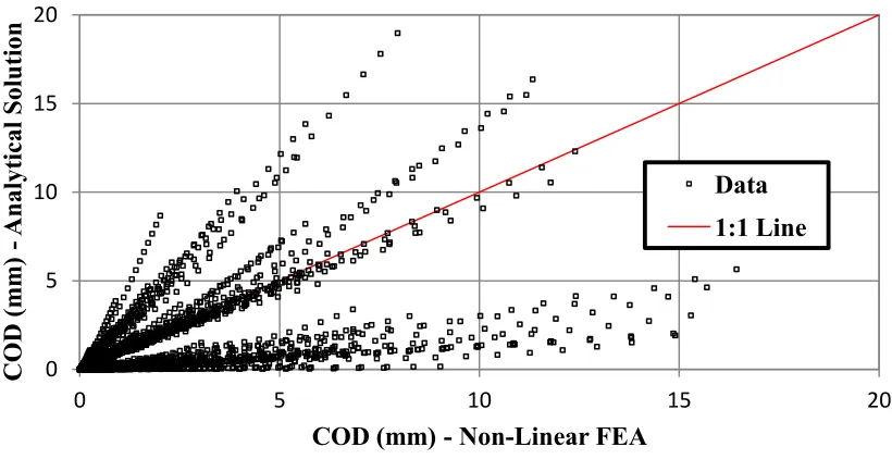
Comparisons of the COD calculation subroutines were made to the FEA Non-Linear Analyses. Because the original subroutines neglected crack face pressure, the FEA for these comparisons did not include crack face pressure. The GE-EPRI solutions calculated by Kumar, V. and German, M.D. (1988) and Rahman, S. et al. (1998-1,2) had a limited normalized crack length of less than 0.5. Figure 1 shows the results of the original code comparison to Non-Linear FEA within this range of normalized crack lengths. If confined to this design space, the results from the analytic solution appear to be representative of the FEA solutions.
phenomenon is not acceptable for probabilistic analyses where the analysis space may yield normalized crack lengths greater than 0.5.
Figure 1. COD w/o crack face pressure ( ) of xLPR v1.0 subroutines vs. Non-Linear FEA ( )
Figure 2. COD w/o crack face pressure ( ) of xLPR v1.0 subroutines vs. Non-Linear FEA ( )
Modified Results
Results from the modified subroutines using the theory advanced in this paper were compared to FEA results which include concurrent axial loading due to internal pressure and crack face pressure with a subsequent bending moment. Two sets of FEA were used in the analysis. The FEA results used in Figure 3 were the same results used to compare against the original results which contained no crack face
0 5 10 15 20
0 5 10 15 20
COD
(m
m
)
Anal
yt
ical S
olu
tion
COD (mm) - Non-Linear FEA
Data
1:1 Line
0 5 10 15 20
0 5 10 15 20
COD
(m
m
)
Anal
yt
ical S
olu
tion
COD (mm) - Non-Linear FEA
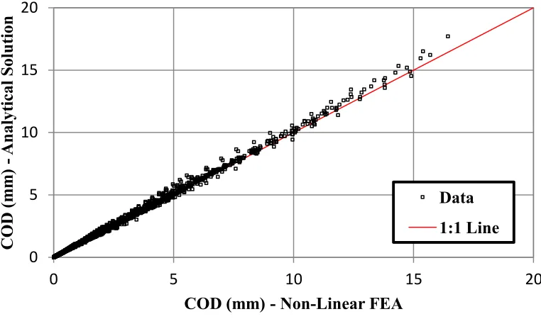
pressure. For the modified resultscomparison to these results, gamma was set equal to zero. As shown in Figure 3, the modified resultsare reasonable when compared to the FEA.
Figure 3. COD ( ) of modified solution vs. Non-Linear FEA ( )
A second set of FEA results were obtained which contained crack face pressure equal to half the internal pressure. Results from the modified subroutines using gamma equal to 0.5 were compared to these FEA results. Again, as shown in Figure 4, the modified subroutine results are reasonable when compared to the FEA.
Figure 4. COD ( .5) of modified solution vs. Non-Linear FEA ( )
0
5
10
15
20
0
5
10
15
20
C
OD
(m
m
)
A
nal
yt
ic
al Sol
ution
COD (mm) - Non-Linear FEA
Data
1:1 Line
0
5
10
15
20
0
5
10
15
20
COD
(m
m
)
Anal
yt
ical S
olu
tion
COD (mm) - Non-Linear FEA
CONCLUSIONS
The work in this study is a continuation of the research initiated by Young et al. (2012). Several key elements to provide an analytical solution are provided. This process has combined the previous useful experiences of other engineers, scientists, and researchers with a refinement in underlying assumptions, application of advanced engineering techniques, and the development of software routines to advance a more general solution.
The following items are a list of key conclusions from this portion the current study:
With regard to the original CALC_COD subroutines:
o Verification and Validation revealed that the routine is only valid for
o Results appear to under-predict the non-linear FEA results over the range of
applicability with the average under-prediction of the analytical results on the order of five percent of the FEA results and a maximum under-prediction of the analytical results on the order of twenty percent of the FEA results.
Based on work in this study, the COD functions are dependent on the rotation characteristics provided by the boundary conditions. Functions to compensate for the crack size as well as the rotation as a function of material characteristics have been developed and implemented.
Work has been completed to provide a solution for axial tension due to pressure plus crack face pressure under concurrent loading with subsequent moment application conditions for a cap-ended pipe with free ends. Equation 24 provides a solution which approximates the finite element solutions.
Preliminary verification and validation have been completed for the given solution and the implementation in the updated CALC_COD subroutine
Cox et al. (2013) investigated the validation of the analytical solution to experimental
results. This validation results in an experimental correction factor as shown in that reference.
With respect to the final solution, the solution estimates the COD for a pipe which is free to rotate at the ends. In reality, the pipe is restrained at the pipe-ends which in turn causes smaller COD values than reported. Together with the current leak-rate software, this may cause a non-conservative result with respect to pipe rupture probabilities. Application of restraint of pressure induced bending results should be investigated such as found in Rahman, S. et al. (1998-3), Kim et al. (2007), Olson et al. (2003), and Feng et al. (2001).
ACKNOWLEDGMENTS
NOMENCLATURE
REFERENCES
Feng, Z., Miura, N., Ghadiali, N., Brust, F., Santos, T., Choi, J.B., Park, C.Y., and Wilkowski, G. (2001). “Effects of Pipe-System Restraint on COD Calculations of Axial Loaded Pipes for LBB Applications – Finite Element Round Robin Results,” Structural Mechanics in Reactor Technology (SMiRT) 16, Washington, DC
Cox, A. J., Young, B.A., and Scott, P.M. (2013) “Advances in COD Equations – Multiple Loading Modes: Validation of the Analytical Models to Experimental Data,” SMiRT 22, San Francisco, CA
Kim, J.-W. (2007). “Evaluation Model for Restraint Effect of Pressure Induced Bending on the Plastic Crack Opening of a Circumferential Throough-Wall Crack,” Nuclear Engineering Technology, Vol. 39, No. 1, pp. 75-84.
Kumar, V. and German, M.D. (1988). “Elastic-Plastic Fracture Analysis of Through-Wall and Surface Flaws in Cylinders,” EPRI Report NP-5596, Research Project 1237-5
Olson, R.J., Morbitzer, R.A., Scott, P.M., and Wilkowski, G.M. (2003) “Practical Application of Restraint of Pressure-Induced Bending Phenomenon in Leak Rate Calculations,” Structural Mechanics in Reactor Technology (SMiRT) 17, Prague, Czech Republic
Rahman, S., Brust, F.W., Ghadiali, N., and Wilkowski, G.M. (1998-1). “Crack-Opening-Area Analyses for Circumferential Through-wall Cracks in Pipes – Part I: Analytical Models,” International Journal of Pressure Vessels and Piping, Vol. 75, pp. 357-373.
Rahman, S., Brust, F.W., Ghadiali, N., and Wilkowski, G.M. (1998-2). “Crack-opening-area analyses for circumferential through-wall cracks in pipes – Part II: model validations,” International Journal of Pressure Vessels and Piping, Vol 75 (1998), pp. 375-396.
Pip Axial Load due to Internal Pressure Collapse Bending Moment
PCFP Axial Load due to Internal Pressure Crack face pressure to internal pressure ratio
Collapse Tension Force Load Ratio
Reference Stress COD
Mean Pipe Radius Elastic COD
Pipe Thickness Plastic COD
Crack Angle (total crack angle = 2θ ) Crack Length (total length = 2a)
Inner Radius of Pipe Strain Hardening Exponent
Internal Pipe Pressure Strength Coefficient
Crack Face Pressure Reference Strain
Far-Field Tension Stress Plastic Influence Function
Cross-Section of Pipe Young’s Modulus
Applied Axial Far-Field Force Elastic Influence Function
Applied Bending Moment Elastic Influence Function for Tension
Loading
Equivalent Bending Moment Elastic Influence Function for Bending Effective Bending Moment (Meq +
Rahman, S., Ghadiali, N., Wilkowski, Moberg, F., and Brickstad, B. (1998-3). “Crack-opening-area analyses for circumferential through-wall cracks in pipes – Part III: off-center cracks, restraint of bending, thickness transitions and weld residual stresses,” International Journal of Pressure Vessels and Piping, Vol 75 (1998), pp. 397-415
Rudland, D.L., Wang, Y.-Y., and Wilkowski (2002), “Comparison of crack-opening predictions for LBB applications,” International Journal of Pressure Vessels and Piping, Vol. 79, pp. 209-217