555-233-119
Comcode 108678665
Issue 1
April 2000
Enterprise Communications Server
Release 8.2
All Rights Reserved Printed in U.S.A.
Notice
Every effort was made to ensure that the information in this book was complete and accurate at the time of printing. However, information is subject to change.
Your Responsibility for Your System’s Security
Toll fraud is the unauthorized use of your telecommunications system by an unauthorized party, for example, persons other than your com-pany’s employees, agents, subcontractors, or persons working on your company’s behalf. Note that there may be a risk of toll fraud associated with your telecommunications system and, if toll fraud occurs, it can result in substantial additional charges for your telecommunications services.
You and your system manager are responsible for the security of your system, such as programming and configuring your equipment to pre-vent unauthorized use. The system manager is also responsible for reading all installation, instruction, and system administration docu-ments provided with this product in order to fully understand the fea-tures that can introduce risk of toll fraud and the steps that can be taken to reduce that risk. Lucent Technologies does not warrant that this product is immune from or will prevent unauthorized use of com-mon-carrier telecommunication services or facilities accessed through or connected to it. Lucent Technologies will not be responsible for any charges that result from such unauthorized use.
Lucent Technologies Fraud Intervention
If you suspect that you are being victimized by toll fraud and you need technical support or assistance, call Technical Service Center Toll Fraud Intervention Hotline at 1 800 643-2353 or contact your local Lucent representative.
Federal Communications Commission Statement
Part 15: Class A Statement. This equipment has been tested and found to comply with the limits for a Class A digital device, pursuant to Part 15 of the FCC Rules. These limits are designed to provide rea-sonable protection against harmful interference when the equipment is operated in a commercial environment. This equipment generates, uses, and can radiate radio-frequency energy and, if not installed and used in accordance with the instructions, may cause harmful interfer-ence to radio communications. Operation of this equipment in a resi-dential area is likely to cause harmful interference, in which case the user will be required to correct the interference at his own expense. Part 68: Network Registration Number. This equipment is registered with the FCC in accordance with Part 68 of the FCC Rules. It is identi-fied by FCC registration number AS593M-13283-MF-E.
Part 68: Answer-Supervision Signaling. Allowing this equipment to be operated in a manner that does not provide proper answer-supervi-sion signaling is in violation of Part 68 Rules. This equipment returns answer-supervision signals to the public switched network when:
• Answered by the called station • Answered by the attendant
• Routed to a recorded announcement that can be administered by the CPE user
This equipment returns answer-supervision signals on all DID calls forwarded back to the public switched telephone network. Permissible exceptions are:
• A reorder tone is received
Canadian Department of Communications (DOC) Interference Information
This digital apparatus does not exceed the Class A limits for radio noise emissions set out in the radio interference regulations of the Canadian Department of Communications.
Le Présent Appareil Nomérique n’émet pas de bruits radioélectriques dépassant les limites applicables aux appareils numériques de la class A préscrites dans le reglement sur le brouillage radioélectrique édicté par le ministére des Communications du Canada.
Trademarks
See the preface of this document. Ordering Information
Call: Lucent Technologies BCS Publications Center
Voice 1 800 457-1235 International Voice 317 322-6416 Fax 1 800 457-1764 International Fax 317 322-6699 Write: Lucent Technologies BCS Publications Center
2855 N. Franklin Road Indianapolis, IN 46219 Order: Document No. 555-233-119
Comcode 108678665 Issue 1, April 2000
For additional documents, refer to the section in “About This Docu-ment” entitled “Related Resources.”
You can be placed on a standing order list for this and other documents you may need. Standing order will enable you to automatically receive updated versions of individual documents or document sets, billed to account information that you provide. For more information on stand-ing orders, or to be put on a list to receive future issues of this docu-ment, contact the Lucent Technologies Publications Center. European Union Declaration of Conformity
The “CE” mark affixed to the DEFINITY® equipment described in this book indicates that the equipment conforms to the following Euro-pean Union (EU) Directives:
• Electromagnetic Compatibility (89/336/EEC) • Low Voltage (73/23/EEC)
• Telecommunications Terminal Equipment (TTE) i-CTR3 BRI and i-CTR4 PRI
For more information on standards compliance, contact your local dis-tributor.
Comments
To comment on this document, return the comment card at the front of the document or email us at document@drmail.lucent.com.
Acknowledgment
Contents
iii
Contents
Contents iii
About This Book xv
■ Purpose xv
■ Intended Audience xv
■ Organization xvi
■ Typographic conventions xvii
■ Admonishments xvii
■ Safety Precautions xviii
■ Security Issues xviii
■ Standards Compliance xix
■ Electromagnetic Compatibility Standards xix
■ Trademarks and Service Marks xxi
■ Related Documents xxii
■ Federal Communications Commission Statement xxii
■ How to Order Documentation xxiv
■ How to Comment on This Document xxiv
■ Where to Call for Technical Support xxv
1
Maintenance for csi systems 1-1■ What’s new for R8csi 1-1
■ How to use the Maintenance book 1-6
■ csi design 1-11
■ Circuit Packs 1-14
■ Maintenance Objects 1-14
■ Alarm and Error Reporting 1-15
■ Maintenance Testing 1-15
■ Preventive Maintenance Procedures 1-18
■ Initialization and Recovery 1-20
■ Set Neon Voltage (Ring Ping) 1-24
■ Logging On/Off 1-26
■ Procedure for SPE-Down Mode 1-38
■ Reseating/Replacing Circuit Packs 1-39
■ Removing Power 1-40
Contents
iv
■ System Backup 1-43
■ Troubleshooting Features 1-47
■ Install DS1 CPE Loopback Jack (T1 Only) 1-71
■ LED Interpretation 1-84
■ Multimedia Call Handling 1-90
■ TN760D Tie Trunk Option Settings 1-98
■ TN464E/F Option Settings 1-101
■ ATM Tips 1-102
■ Unusual ATM trouble conditions 1-132
■ Troubleshooting Multimedia Call Handling
(MMCH) 1-135
2
Maintenance Commands 2-1■ System Command Structure 2-1
■ busyout access-endpoint 2-2
■ busyout board 2-3
■ busyout cdr-link 2-5
■ busyout data-module 2-6
■ busyout journal-printer 2-7
■ busyout link 2-9
■ busyout mis 2-10
■ busyout pms-link 2-11
■ busyout port 2-12
■ busyout pri-endpoint 2-13
■ busyout sp-link 2-15
■ busyout station 2-15
■ busyout tdm 2-16
■ busyout tone-clock 2-17
■ busyout trunk 2-18
■ cancel hardware-group 2-20
■ change circuit-packs 2-20
■ change synchronization 2-22
■ change system-parameters customer-options 2-24
■ change system-parameters maintenance 2-24
■ clear audits 2-36
Contents
v
■ clear interface 2-37
■ clear isdn-testcall 2-38
■ clear link 2-38
■ clear mst 2-39
■ clear pkt 2-39
■ clear port 2-39
■ disable administered-connection 2-39
■ disable mst 2-40
■ disable suspend-alm-orig 2-40
■ disable synchronization-switch 2-41
■ disable test-number 2-41
■ display alarms 2-41
■ display capacity 2-47
■ display communication-interface hop-channels 2-58
■ display communication-interface links 2-59
■ display disabled-tests 2-60
■ display errors 2-61
■ display events 2-67
■ display initcauses 2-69
■ display memory-configuration 2-72
■ display node-names 2-73
■ display port 2-75
■ display synchronization 2-76
■ display system-parameters duplication 2-77
■ display system-parameters maintenance 2-79
■ display test-schedule 2-88
■ display time 2-91
■ download update-file 2-92
■ enable administered-connection 2-95
■ enable mst 2-95
■ enable suspend-alm-orig 2-95
■ enable synchronization-switch 2-96
■ enable test-number 2-97
■ format card-mem 2-97
Contents
vi
■ list communication-interface processor-channel 2-99
■ list configuration 2-101
■ list configuration software-version 2-104
■ list disabled-mos 2-109
■ list external-device alarm 2-110
■ list history 2-111
■ list ip-route 2-114
■ list isdn-testcall 2-115
■ list marked-ports 2-116
■ list measurements clan ethernet 2-117
■ list measurements clan ppp 2-119
■ list measurements ds-1 2-121
■ list mst 2-125
■ list suspend-alm-orig 2-149
■ list sys-link 2-150
■ list testcalls 2-151
■ mark port 2-156
■ monitor bcms 2-157
■ monitor health 2-161
■ monitor security-violations 2-164
■ monitor system 2-165
■ monitor traffic 2-171
■ monitor trunk 2-173
■ netstat ip-route 2-174
■ ping 2-175
■ recycle carrier 2-179
■ release access-endpoint 2-179
■ release board 2-180
■ release cdr-link 2-181
■ release data-module 2-182
■ release journal-printer 2-183
■ release link 2-185
■ release mis 2-186
■ release modem-pool 2-187
Contents
vii
■ release port 2-189
■ release pri-endpoint 2-190
■ release sp-link 2-191
■ release station 2-192
■ release tdm 2-193
■ release tone-clock 2-194
■ release trunk 2-195
■ reset board 2-196
■ reset io-processor 2-197
■ reset interface 2-197
■ reset packet-interface 2-198
■ reset switch-control 2-198
■ reset system 2-199
■ reset translation-id 2-199
■ restore announcements 2-200
■ resume hardware-group 2-202
■ save announcements 2-203
■ save translation 2-204
■ set options 2-205
■ set signaling-group 2-211
■ set synchronization 2-212
■ set tdm 2-212
■ set time 2-213
■ set tone-clock 2-214
■ set vector 2-214
■ status access-endpoint 2-216
■ status administered-connection 2-217
■ status attendant 2-218
■ status audits 2-219
■ status bri-port 2-228
■ status card-mem 2-234
■ status cdr-link 2-237
■ status cleared-alarm-notif 2-239
■ status conference 2-239
Contents
viii
■ status esm 2-276
■ status hardware-group 2-277
■ status health 2-279
■ status interface 2-282
■ status isdn-testcall 2-283
■ status journal-link 2-284
■ status link n 2-285
■ status packet-interface 2-290
■ status pms-link 2-291
■ status pri-endpoint 2-292
■ status processor-channel 2-294
■ status signaling-group 2-296
■ status sp-link 2-298
■ status station 2-299
■ status synchronization 2-301
■ status sys-link 2-302
■ status system 2-304
■ status trunk 2-308
■ status tsc-administered 2-311
■ status tti 2-312
■ test access-endpoint 2-314
■ test alarms 2-315
■ test analog-testcall 2-320
■ test board 2-323
■ test card-mem 2-325
■ test cdr-link 2-328
■ test customer-alarm 2-330
■ test data-module 2-331
■ test ds1-loop 2-333
■ test eda-external-device-alrm 2-335
■ test environment 2-337
■ test hardware-group 2-340
■ test inads-link 2-346
■ test interface 2-348
Contents
ix
■ test journal-printer 2-351
■ test led 2-353
■ test memory 2-354
■ test network-control 2-357
■ test pkt 2-359
■ test packet-interface 2-360
■ test pms-link 2-362
■ test port 2-365
■ test pri-endpoint 2-367
■ test processor 2-369
■ test signaling-group 2-371
■ test sp-link 2-372
■ test station 2-374
■ test synchronization 2-376
■ test sys-link 2-378
■ test tdm 2-381
■ test tone-clock 2-383
■ test trunk 2-385
■ test tsc-administered 2-387
■ traceroute 2-388
■ upgrade software 2-390
3
Maintenance Objects 3-1■ 12V-PWR (12 Volt Power Supply) 3-1
■ ADM-CONN (Administered Connection) 3-5
■ ADX8D-BD (AUDIX Circuit Pack) 3-9
■ ADX8D-PT (AUDIX Digital Port) 3-10
■ ADX16D-B (16 Port AUDIX Circuit Pack) 3-17
■ ADX16A-BD (AUDIX Circuit Pack) 3-18
■ ADX16D-P (16-Port AUDIX Digital Port) 3-19
■ ADX16A-PT (AUDIX Analog Line/Control Link) 3-27
■ ALARM-PT (ALARM PORT) 3-34
■ ANL-24-L (24-Port Analog Line) 3-35
■ ANL-BD (Analog Line Circuit Pack) 3-51
■ ANL-LINE (8-Port Analog Line),
Contents
x
■ AN-LN-PT (Analog Line
Port) 3-72
■ ANN-BD (Announcement Circuit Pack) 3-92
■ ANN-PT (Announcement Port) 3-110
■ ANNOUNCE (Announce) 3-121
■ ATM-BCH (ATM B-Channel Trunk) 3-125
■ ATM-DCH (ATM D-Channel Port) 3-139
■ ATM-EI (Expansion Interface Circuit Pack) 3-142
■ ATM-INTF (TN2305/6) 3-187
■ ATM-NTWK (ATM Network Error) 3-190
■ ATM PNC-DUP
(ATM PNC Duplication) 3-198
■ ATM-SGRP (ATM Signaling Group) 3-209
■ ATM-SYNC (ATM Synchronization) 3-220
■ ATM-TRK (Circuit Emulation Service
Circuit Pack) 3-227
■ AXA12-BD/ADX8D-BD/AXD12-BD (AUDIX
Circuit Packs) 3-258
■ AXA12-RS/ADX8D-RS/AXD12-RS (AUDIX
Reserve Slots) 3-259
■ BRI-BD/LGATE-BD (ISDN-BRI Line Circuit Pack) 3-260
■ BRI-DAT (ISDN-BRI) 3-267
■ BRI-PORT (ISDN-BRI Port),
ABRI-PORT (ASAI ISDN-BRI Port) 3-268
■ BRI-SET, ASAI-ADJ, BRI-DAT 3-290
■ CABINET (Cabinet Sensors) 3-318
■ CAP-MEM (Memory Card Capacity) 3-324
■ CARD-MEM (Memory Card) 3-327
■ CLAN-BD (Control LAN Circuit Pack) 3-347
■ CLSFY-BD (Call Classifier Circuit Pack) 3-365
■ CLSFY-PT (Call Classifier Port) 3-366
■ CO-BD (Central Office Trunk Circuit Pack) 3-372
■ CO-DS1 (DS1 CO Trunk) 3-373
■ CO-TRK (CO Trunk) 3-389
■ CONFIG (System Configuration) 3-415
■ CUST-ALM (Customer-Provided Alarming Device) 3-416
Contents
xi
■ DATA-CHL (Data Channel) 3-424
■ DATA-CON (Network Control Driver) 3-449
■ DAT-LINE (Data Line) 3-451
■ DETR-BD (International Version) 3-459
■ DID-BD (Direct Inward Dial Trunk Circuit Pack) 3-460
■ DID-DS1 (DS1 DID Trunk) 3-461
■ DID-TRK (DID Trunk) 3-472
■ DIG-BD (Digital Line Circuit Pack) 3-489
■ DIG-IP-STN (Digital IP Station) 3-490
■ DIG-LINE (Digital Line) 3-498
■ DIOD-DS1 (DS1 DIOD Trunk) 3-523
■ DIOD-TRK (DIOD Trunk), DIOD-BD
(DIOD Circuit Pack) 3-534
■ DIOD-TRK (DIOD Trunk) 3-535
■ DLY-MTCE (MO-DAILY) 3-545
■ DS1-BD (DS1 Interface Circuit Pack) 3-548
■ DT-LN-BD (Data Line Circuit Pack) 3-622
■ DTMR-PT [Dual Tone Multifrequency Port (TTR)] 3-623
■ E-DIG-BD (Multi Application Platform Board) 3-628
■ E-DIG-STA (Emulated Digital Line) 3-630
■ EMG-XFER 3-640
■ ERR-LOG (Error Log) 3-643
■ ETH-PT (Control LAN Ethernet) 3-644
■ ETR-PT (Enhanced Tone Receiver Port) 3-655
■ EXT-DEV ADMIN? N (External Device Alarm) 3-662
■ EXT-DEV ADMIN? Y (External Device Alarm) 3-665
■ GPTD-PT [General Purpose Tone
Detector Port (CPTR)] 3-668
■ H323-BCH (H.323 B-Channel) 3-669
■ H323-SGRP (H.323 Signaling Group) 3-671
■ H323-STN (H.323 IP Station) 3-677
■ HYB-BD (Hybrid Line Circuit Pack) 3-683
■ HYB-LINE (Hybrid Line) 3-684
■ INADS (INADS Link) 3-705
■ IO-PROCR (I/O Processor) 3-708
Contents
xii
■ ISDN-SGR (ISDN-PRI Signaling Group) 3-717
■ ISDN-TRK (DS1 ISDN Trunk) 3-733
■ LOG-SVN (Login Security Violation) 3-760
■ JNL-PRNT (Journal Printer Link) 3-763
■ MAPD-BD (MAPD Interface Circuit Pack TN802) 3-764
■ MEDPRO (Media Processor MAPD Circuit Pack) 3-794
■ MEDPROPT (TN802 MED PRO DSP PORT) 3-806
■ MET-BD (MET Line Circuit Pack) 3-812
■ MET-LINE (MET Line) 3-813
■ MIS (Management Information System) 3-832
■ MMI-BD 3-833
■ MMI-LEV (Multimedia Interface Resource Level) 3-842
■ MMI-PT 3-845
■ MMI-SYNC 3-851
■ OPS-LINE (DS1 OPS Line) 3-853
■ PE-BCHL (PRI Endpoint Port) 3-865
■ PKT-BUS (Packet Bus) 3-885
■ PKT-INT (Packet Interface) 3-894
■ PMS-LINK (Property Management System Link) 3-914
■ PMS-PRNT/JNL-PRNT (PMS Printer Link) 3-922
■ PPP-PT (Control LAN Packet/Port) 3-928
■ PR-MAINT (Maintenance Processor) 3-941
■ PR-MEM (RISC Memory) 3-954
■ PRI-CDR/SEC-CDR (PRI-CDR Link) 3-961
■ PROCR (RISC Processor Circuit Pack TN798) 3-968
■ PROC-SAN (Process Sanity Audits) 3-975
■ RING-GEN (Analog Ring Generator) 3-976
■ S-SYN-BD (Speech Synthesis Circuit Pack) 3-980
■ S-SYN-PT (Speech Synthesis Port) 3-981
■ SEC-CDR (SEC-CDR Link Maintenance) 3-994
■ SW-CTL (Switch Control) 3-995
■ SYNC (Synchronization) 3-1003
■ SYS-LINK (System Links) 3-1010
■ SYS-PRNT (System Printer) 3-1015
Contents
xiii
■ TBRI-BD (TN2185
ISDN Trunk-Side BRI) 3-1023
■ TBRI-PT (TN2185
ISDN Trunk-Side BRI Port) 3-1031
■ TBRI-TRK (TN2185
ISDN Trunk-Side BRI) 3-1051
■ TDMODULE (Trunk Data Module) 3-1062
■ TDM-BUS (TDM Bus) 3-1063
■ TDM-CLK (TDM Bus Clock) 3-1079
■ TIE-BD (Tie Trunk Circuit Pack) 3-1089
■ TIE-DS1 (DS1 Tie Trunk) 3-1090
■ TIE-TRK (Tie Trunk) 3-1106
■ TONE-BD (Tone-Clock Circuit Pack) 3-1128
■ TONE-PT (Tone Generator) 3-1139
■ TRANS-ID (Translation-ID) 3-1147
■ TR-LN-BD (Trunk Line
Board) 3-1152
■ TSC-ADM (Administered Temporary
Signaling Connections) 3-1153
■ TTR-LEV (TTR Level) 3-1159
■ UDS1-BD (UDS1 Interface Circuit Pack) 3-1163
■ VC-BD 3-1257
■ VC-DSPPT 3-1261
■ VC-LEV (Voice Conditioner
DSP Port Level) 3-1270
■ VC-SUMPT 3-1273
■ WAE-PORT (Wideband Access Endpoint Port) 3-1278
■ XXX-BD (Common Port Circuit Pack) 3-1285
Contents
About This Book
xv Purpose
About This Book
Purpose
This book contains the information needed to monitor, test, and maintain DEFINITY®Enterprise Communications Server (ECS) csi system and covers many of the faults and troubles that can occur in the system. Most maintenance requirements are simple procedures due to the modular, self-testing nature of the system.
Simple, traditional troubleshooting methods are sometimes sufficient to locate and clear faults. The traditional methods include terminal substitution, visual inspections, continuity checks, and clarification of operating procedures with users.
Intended Audience
The information in this book is intended for use by:
■ A maintenance technician dispatched to a DEFINITY System site in response to a trouble alarm or a user trouble report
■ A maintenance technician located at a remote maintenance facility
About This Book
xvi Organization
Each DEFINITY System has a user-designated System Manager who is responsible for system administration and with whom the maintenance technician should work closely.
This book is not intended to solve all levels of troubles. It is limited to troubles that can be solved by using the Alarm Log, Error Log, trouble-clearing procedures, maintenance tests, and traditional troubleshooting methods. If the trouble still has not been resolved, it is the responsibility of the maintenance technician to escalate the problem to a higher level of technical support. Escalation should conform to the procedures in the Technical and Administration Escalation Plan.
Organization
This book consists of two volumes: Volume 1 contains Chapters 1 and 2; Volume 2 contains Chapter 3.
■ Chapter 1, ‘‘Maintenance for csi systems’’ describes the system’s design
and maintenance strategy, including circuit packs, how power is supplied to the system, the various reset and reboot processes (and how these processes are used to perform maintenance and to recover systems or subsystems that are out of service), common maintenance tasks (including removing and installing circuit packs, removing and restoring power, system backups, upgrading software, and various testing and troubleshooting procedures), and interpreting circuit pack LEDs.
■ Chapter 2, ‘‘Maintenance Commands’’ explains how to use the
maintenance commands including specific command syntax, typical forms, and display output.
■ Chapter 3, ‘‘Maintenance Objects’’ has specific troubleshooting and repair instructions for every maintenance component in the system. This chapter also contains repair procedures for system-alarmed and user- reported troubles. For each Maintenance Object (MO), a table lists the alarm level, hardware error associated with the MO, the associated test that caused the error, the test sequences and the specific command line entry required to run the tests, and a brief description of each test. Explanations of error codes associated with each test are given along with specific maintenance procedures used to resolve each problem.
About This Book
xvii Typographic conventions
Typographic conventions
This document uses the following typographic conventions:
■ Information you type at the management terminal is shown in the following typeface: list system-parameters maintenance.
■ Information displayed on the management terminal screen is shown in the following typeface: login.
■ Keyboard keys are shown in the following typeface: Enter.
The following conventions describe the systems referred to in this document.
■ The word “system” generally refers to the DEFINITY Enterprise Communications Server.
■ Circuit pack codes (such as TN798 or TN2182B) are shown with the minimum acceptable alphabetic suffix (like the “B” in the code TN2182B).
Generally, an alphabetic suffix higher than that shown is also acceptable. However, not every vintage of either the minimum suffix or a higher suffix code is necessarily acceptable.
NOTE:
Refer to Technical Monthly: Reference Guide for Circuit Pack Vintages and Change Notices, for current information about the usable vintages of specific circuit pack codes (including the suffix). The term “ASAI” is synonymous with the newer CallVisor ASAI.
■ DEFINITY Enterprise Communications Server is abbreviated as DEFINITY ECS.
Admonishments
Admonishments used in this book have the following meanings:
!
CAUTION:
This sign is used to indicate possible harm to software, possible loss of data, or possible service interruptions.
!
WARNING:
This sign is used where there is possible harm to hardware or equipment.
!
DANGER:
About This Book
xviii Safety Precautions
Safety Precautions
When performing maintenance or translation procedures on the system, users must observe certain precautions. Observe all caution, warning, and danger admonishments to prevent loss of service, possible equipment damage, and possible personal injury. In addition, the following precautions regarding electromagnetic interference (EMI) and static electricity must be observed:
Electromagnetic Interference
This equipment generates, uses, and can radiate radio frequency energy. Electromagnetic fields radiating from the switch may cause noise in the
customer’s equipment. If the equipment is not installed and used in accordance with the instruction book, radio interference may result.
!
WARNING:
To maintain the EMI integrity of the system, maintenance personnel must ensure that all cabinet panels, covers, and so forth, are firmly secured before leaving the customer’s premises.
Static Electricity
To prevent or reduce electrostatic discharge (ESD), maintenance personnel must always attach wrist grounding straps before working on switch components or handling circuit packs.
!
CAUTION:
Electrostatic discharge can damage or destroy circuit packs containing integrated circuits (ICs).
The ESD wrist strap, cable assembly, and spare fuses are packed in a plastic bag and placed in the top of the system cabinet. Use the ESD wrist strap when troubleshooting, performing maintenance, or handling any circuit packs associated with the system.
Security Issues
A number of matters concerning maintenance are affected by security issues. For details, be sure to consult the BCS Products Security Handbook,
555-025-600.
!
CAUTION:
About This Book
xix Standards Compliance
Standards Compliance
The equipment presented in this document complies with the following (as appropriate):
■ ITU-T (Formerly CCITT)
■ ECMA
■ ETSI
■ IPNS
■ DPNSS
■ National ISDN-1
■ National ISDN-2
■ ISO-9000
■ ANSI
■ FCC Part 15 and Part 68
■ EN55022
■ EN50081
■ EN50082
■ CISPR22
■ Australia AS3548 (AS/NZ3548)
■ Australia AS3260
■ IEC 825
■ IEC950
■ UL 1459
■ UL1950
■ CSA C222 Number 225
■ TS001
Electromagnetic Compatibility
Standards
This product complies with and conforms to the following:
■ Limits and Methods of Measurements of Radio Interference Characteristics of Information Technology Equipment, EN55022 (CISPR22), 1993
About This Book
xx Electromagnetic Compatibility Standards
■ FCC Parts 15 and 68
■ Australia AS3548
NOTE:
The system conforms to Class A (industrial) equipment; voice terminals meet Class B requirements.
■ Electrostatic Discharge (ESD) IEC 1000-4-2
■ Radiated radio frequency field IEC 1000-4-3
■ Electrical Fast Transient IEC 1000-4-4
■ Lightning effects IEC 1000-4-5
■ Conducted radio frequency IEC 1000-4-6
■ Mains frequency magnetic field IEC 1000-4-8
■ Low frequency mains disturbance
The system conforms to the following:
■ Electromagnetic compatibility General Immunity Standard, part 1; residential, commercial, light industry, EN50082-1, CENELEC, 1991
■ Issue 1 (1984) and Issue 2 (1992), Electrostatic discharge immunity requirements (EN55024, Part 2) IEC 1000-4-2
■ Radiated radio frequency field immunity requirements IEC 1000-4-3
■ Electrical fast transient/burst immunity requirements IEC 1000-4-4
European Union Standards
Lucent Technologies Business Communications Systems declares that the DEFINITY equipment specified in this document bearing the “CE” mark conforms to the European Union Electromagnetic Compatibility Directives.
The “CE” (Conformité Europeénne) mark indicates conformance to the:
■ European Union Electromagnetic Compatibility Directive (89/336/EEC)
■ Low Voltage Directive (73/23/EEC)
■ Telecommunication Terminal Equipment (TTE) Directive (91/263/EEC)
■ i-CTR3 Basic Rate Interface (BRI) and i-CTR4 Primary Rate Interface (PRI) as applicable.
The “CE” mark is applied to the following products:
■ Global AC powered Multi-Carrier Cabinet (MCC)
■ DC powered Multi-Carrier Cabinet (MCC) with 25-Hz ring generator
About This Book
xxi Trademarks and Service Marks
■ AC powered Compact Single-Carrier Cabinet (CSCC) with 25-Hz ring generator
■ Enhanced DC Power System
Trademarks and Service Marks
The following are trademarks or registered trademarks of Lucent Technologies:
■ 5ESS
™,
4ESS™
■ AUDIX®■ Callvisor®
■ Callmaster®
■ CentreVu™
■ CONVERSANT®
■ DEFINITY®
■ DIMENSION®
■ MERLIN®
■ VOICE POWER®
The following are trademarks or registered trademarks of AT&T:
■ ACCUNET®
■ DATAPHONE®
■ MEGACOM®
■ MULTIQUEST®
■ TELESEER®
The following are trademarks or registered trademarks of other companies:
■ Ascend®(registered trademark of Ascend, Inc.)
■ Audichron® (registered trademark of the Audichron Company)
■ MS-DOS® (registered trademark of the Microsoft Corporation)
■ MicroChannel® (registered trademark of IBM Systems)
■ MULTIQUEST® (registered trademark of Telecommunications Service)
■ PagePac® (trademark of the Dracon Division of the Harris Corporation)
About This Book
xxii Related Documents
Related Documents
DEFINITY ECS Release 8.2 — Installation and Test for Compact Modular Cabinets, 555-233-118
Provides procedures and information for hardware installation and initial testing of compact modular cabinets.
DEFINITY ECS Release 8.2— Installation for Adjuncts and Peripherals,
555-233-116
Provides procedures and information for hardware installation and initial testing of ECS adjunct and peripheral systems and equipment.
BCS Products Security Handbook, 555-025-600
Provides information about the risks of telecommunications fraud and measures for addressing those risks and preventing unauthorized use of BCS products. This document is intended for telecommunications managers, console operators, and security organizations within companies.
Federal Communications Commission
Statement
Part 68: Statement
Part 68: Answer-Supervision Signaling. Allowing this equipment to be operated in a manner that does not provide proper answer-supervision signaling is in violation of Part 68 rules. This equipment returns answer-supervision signals to the public-switched network when:
■ Answered by the called station
■ Answered by the attendant
■ Routed to a recorded announcement that can be administered by the CPE user
This equipment returns answer-supervision signals on all DID calls forwarded back to the public-switched telephone network, with these exceptions:
■ A call is unanswered
■ A busy tone is received
■ A reorder tone is received
This equipment is capable of providing users access to interstate providers of operator services through the use of access codes. Modification of this
About This Book
xxiii Federal Communications Commission Statement
This equipment complies with Part 68 of the FCC Rules. On the rear of this equipment is a label that contains, among other information, the FCC registration number and ringer equivalence number (REN) for this equipment. If requested, this information must be provided to the telephone company. The REN is used to determine the number of devices connected to the telephone line. Excessive RENs on the telephone line may result in devices not ringing in response to an incoming call. In most, but not all areas, the sum of RENs should not exceed 5.0. To be certain of the number of devices that can be connected to a line, as determined by the total RENs, contact the local telephone company.
NOTE:
REN is not required for some types of analog or digital facilities.
Means of Connection
Connection of this equipment to the telephone network is shown in the following table.
If the terminal equipment (DEFINITY® System) causes harm to the telephone network, the telephone company may notify you in advance that temporary discontinuance of service is be required. But if advance notice is not practical, the telephone company may notify the customer as soon as possible. Also, you will be advised of your right to file a complaint with the FCC if you believe it is necessary.
The telephone company may make changes in its facilities, equipment,
operations, or procedures that could affect the operation of the equipment. If this happens, the telephone company will provide advance notice so you can make the necessary modifications to maintain uninterrupted service.
Manufacturer’s Port
Identifier FIC Code
SOC/REN/
A.S. Code Network Jacks
Off/On Premises Station OL13C 9.0F RJ2GX, RJ21X, RJ11C
DID Trunk 02RV2-T 0.0B RJ2GX, RJ21X
CO Trunk 02GS2 0.3A RJ21X
CO Trunk 02LS2 0.3A RJ21X
Tie Trunk TL31M 9.0F RJ2GX
About This Book
xxiv How to Order Documentation
If trouble is experienced with this equipment or for repair or warranty information, please contact the Technical Service Center at 1-800-248-1234. If the equipment causes harm to the telephone network, the telephone company may request that you disconnect the equipment until the problem is resolved.
It is recommended that repairs be performed by Lucent Technologies-certified technicians.
The equipment cannot be used on public coin phone service provided by the telephone company. Connection to party line service is subject to state tariffs. Contact the state public utility commission, public service commission, or corporation commission for information.
This equipment, if it uses a telephone receiver, is hearing aid compatible.
How to Order Documentation
In addition to this book, other description, installation and test, maintenance, and administration books are available. A complete list of DEFINITY books can be found in the Business Communications System Publications Catalog,
555-000-010.
This document and any other DEFINITY documentation can be ordered directly from the Lucent Technologies Business Communications System Publications Fulfillment Center toll free at 1-800-457-1235 (voice) and 1-800-457-1764 (fax). International customers should use 317-322-6791 (voice) and 317-322-6849 (fax).
How to Comment on This Document
Lucent Technologies welcomes your feedback. Please fill out the reader
comment card found at the front of this manual and return it. Your comments are of great value and help improve our documentation.
About This Book
xxv Where to Call for Technical Support
Where to Call for Technical Support
Use the following telephone number for the region in which the system is installed.
Organization
Telephone Number
Streamlined Implementation (for missing equipment)
1-800-772-5409
USA/Canada Technical Service Center 1-800-248-1234
Technical Service Center (INADS Database Administration)
1-800-248-1111
Asia/Pacific Regional Support Center 65-872-8686
Western Europe/South Africa/Middle East 441-242-774-800
Business Communications Europe 441-242-391-789
Eastern/Central Europe 361-345-4334
ITAC 1-303-804-3777
Latin/Central America & Caribbean 1-303-804-3778
DEFINITY Helpline 1-800-225-7585
Lucent Technologies Toll Fraud Intervention 1-800-643-2353
Lucent Technologies Technical Service Center 1-800-242-2121
Lucent Technologies Corporate Security 1-800-822-9009
About This Book
Maintenance for csi systems
1-1 What’s new for R8csi
1
1
Maintenance for csi systems
The maintenance subsystem is a part of the software that initializes and maintains the system. The software continuously monitors system health and keeps a record of errors detected in the system. The maintenance subsystem also provides a user interface for on-demand testing. This chapter provides a brief description of the maintenance strategy and background information on the system’s overall functions.
What’s new for R8csi
The following sections introduce new features in the Maintenance manuals:
■ ‘‘H323-BCH’’
■ ‘‘H323-SGRP’’
■ ‘‘H323-STN’’
■ ‘‘DIG-IP-STN’’
■ ‘‘MEDPRO’’
■ ‘‘MEDPROPT’’
■ ‘‘AN-LN-PT (and TR-LN-BD)’’
■ ‘‘Administrable Loss Plan’’
■ ‘‘Traceroute’’
Maintenance for csi systems
1-2 What’s new for R8csi
1
H323-BCH
H.323 signaling is very similar to ISDN Q.931 signaling. In order to take advantage of existing Definity ISDN call processing software, H.323 trunk call processing includes H.323 signaling groups, H.323 D-channels and H.323 B-channels. H.323 Signaling groups are similar in concept to ISDN PRI signaling groups. H.323 D-channels are an artificial fabrication created only to allow maximum re-use of system ISDN code. H.323 B-channels are also an artificial fabrication.
H323-SGRP
The H.323 Signaling Group (H323-SGRP) maintenance object supports a signaling channel for H.323 Trunk connections. The Media Processor (MedPro) TN802B circuit pack provides audio connectivity, working in concert with a C-LAN (TN799B) circuit pack that provides control signaling to support an H.323 connection.
The H.323 signaling group (323-SGRP) is a signaling channel that physically rides on a C-LAN ethernet port (socket) and the IP network. Unlike ISDN
D-channels, the H.323 channel may actually come up and down on a call by call basis. The H.323 channel is actually a TCP/IP signaling channel. Layers 1 and 2 of this signaling channel are monitored by IP PING testing.
H323-STN
This maintenance object covers implementation of the maintenance for native mode H.323 endpoints. Native mode H.323 applications such as NetMeeting or Proshare only provide what is needed to support the H.323 standard. There is very little that Definity can invoke in the maintenance area. Definity will report errors as they are detected via the RAS registration and keep-alive mechanism. Definity will PING the endpoint both via the signaling path (i.e. via C-LAN) and via the media path (i.e. via Medpro).
This station type is not attached to a port board. Insertion of the station is not driven by board insertion, rather it is driven by successful registration of the endpoint. It is maintained via a set of explicit TCP/IP ping requests and errors reported by the switch software, which terminates the H.323 signaling portion of each endpoint. The MO follows standard maintenance methodology and supports test, busyout, release and status commands.
DIG-IP-STN
Maintenance for csi systems
1-3 What’s new for R8csi
1
Lucent-provided endpoint consists of a service provider, an application layer called the Telephony Manager, and a registration application. The service provider terminates DCP signaling carried over TCP. The Telephony Manager provides the GUI emulating the DCP set. The registration application handles H323.RAS and is used to register and authenticate the endpoint with DEFINITY. This group of modules is called Vphone. Note that the Vphone does not include any type of audio path of bearer channel. The Vphone provides a DCP control plane for an alternate bearer channel. Tha alternate bearer channel is provided by either a native H.323 station or a POTS line or trunk. The Vphone is used only in a dual-connect arrangement.
The Vphone supports some level of existing DCP maintenance in the form of audits and updates.
This station type is not attached to a port board. Insertion of the station is not driven by board insertion, rather it is driven by successful registration of the endpoint. It is maintained via a set of explicit TCP/IP ping requests and errors reported by the User Manger software, which terminates the H.323 signaling portion of each endpoint. The MO follows standard mtce methodology and supports test, busyout, release and status commands.
MEDPRO
The TN802B MedPro circuit board is used by the DOLAN (Definity on the LAN) feature to provide voice over IP connectivity. The TN802B can run either:
■ R8.1 IP Trunk application — allows the TN802B to emulate a DS1 circuit pack. In this mode, the circuit pack is maintained as a standard DS1 board with its associated Tie trunk ports. The TN802B operates as an integrated Internet Telephony Server. It communicates with other ITS boxes or IP trunk boards.
■ the Media Processor (MedPro) application — allows the TN802B to act as a service circuit to terminate generic RTP streams used to carry
packetized audio over an IP network. As part of the overall H.323 implementation, the TN802B or later circuit pack handles the audio streams while the TN799 C-LAN handles the TCP/IP signaling channels. This maintenance plan applies only to a TN802B MedPro running the Media Processor application.
The MedPro hardware combines an angel complex, a Windows NT PC and a TAP802 DSP card in a 3-slot package. When operating as an IP trunk circuit pack, the MedPro emulates a DS1 Tie Trunk circuit pack and blindly responds to DS1 trunk maintenance requests. Actual maintenance is accomplished via the windows NT interface and the ITS software diagnostics.
Maintenance for csi systems
1-4 What’s new for R8csi
1
MEDPROPT
The MEDPROPT maintenance object monitors the health of the MEDPRO digital signal processors (DSPs).
The TN802B MAPD (Multi-Application Platform for DEFINITY) Media Processor circuit pack provides the audio bearer channels for H.323 voice over IP calls. One TN802B circuit pack has one MEDPROPT media processing resource. Based on system administration of audio codecs, a MEDPROPT can handle either 31 or 22 simultaneous channels of H.323 audio processing. If the
ip-parameters form specifies only G.711 Mulaw or G.711 Alaw as the audio
codecs, the MEDPROPT can service 31 channels. If any other codec type (G.723-5.3K, G.723-6.3K, or G.729) is administered, the MEDPROPT can only service 22 channels.
The MEDPROPT is physically made up of 11 individual DSPs, but is treated logically as one port. If individual DSPs on the TN802B MAPD fail, the MEDPROPT remains in-service at lower capacity.
The MEDPROPT is a shared service circuit. It is shared between H.323 trunk channels and H.323 stations. An idle channel is allocated to an H.323 trunk/station on a call-by-call basis.
AN-LN-PT (and TR-LN-BD)
The TN793B/TN2793B Analog Line circuit pack (w/ Caller ID), and the TN797 Analog Trunk and Line circuit pack both support this Maintenance Object.
The TN793B/TN2793B Analog Line circuit pack (w/ Caller ID) provides 24 ports for voice terminals and supports both on-premises and off-premises analog voice terminals.
The TN797 Analog Trunk and Line circuit pack provides 8 ports, each of which may be administered in any of several ways, as described in maintenance object TR-LN-BD.
NOTE:
Maintenance for csi systems
1-5 What’s new for R8csi
1
Administrable Loss Plan
The administrable Loss Plan feature provides the user with the capability to administer the loss or gain applied on calls. This plan provides for dynamic administration of loss levels per station, using 2- party loss tables, and an algorithm that calculates 3, 4, 5, and 6-party conference loss plans. Such a feature can be used to provide additional gain, for example, on connections involving station sets whose users have hearing impairments.
Implementation of this plan involves the addition of a new field, Digital Loss Plan Modifications: on the system-parameters customer options form.
Traceroute
This command provides the ability to trace the route of packets originated from DEFINITY IP boards through the LAN. The output shows the ip address of each router or host (hop) that the packets encounter and the time elapsed between each hop. If a DEFINITY IP board has trouble communicating with a far-end device, the traceroute command can determine “how far” packets get toward the destination.
DEFINITY IP boards include:
■ TN799B (or later suffix) CLAN board
■ TN802B Medpro board
The output form lists:
■ Hops traversed from source to destination
■ IP addresses of the hop points and the final destination
■ Observed round-trip delay from the source to each hop point
If no reply is received from a potential hop point, the IP Address field contains stars (*), which indicates a timeout condition.
The primary use of this command is to determine quickly and unambiguously if the fault lies within Lucent-provided equipment or if the fault is with the LAN or LAN administration to which the DEFINITY ECS switch is connected.
Incomplete Command Timeout
A time-out feature has been added to the MAINTENANCE-RELATED SYSTEM PARAMETERS form (accessed by the command change system parameters
maintenance). This feature improves the operation of daily maintenance by
Maintenance for csi systems
1-6 How to use the Maintenance book
1
■ Options for blank, 1, 2, 3, 4, 5, or 6 hours (the default is 2 hours)
■ The blank option indicates that the feature is not active
■ Only commands that block the running of daily maintenance (add, change, duplicate, remove, and set) are affected
■ All logins will time-out if any of these commands are active for the prescribed time (except for the “blank” option)
■ The feature applies to all logins, regardless of type (init, dadmin, craft, inads) or permissions granted to the specific login ID of an administration or maintenance user
The corresponding “time-out” entry is appended to the list history log.
How to use the Maintenance book
This procedure begins with the system raising an alarm against a Maintenance Object (MO), a software module that monitors the components of a circuit pack. These components can include:
■ Hardware
■ System (processor) availability and conditions
■ Presence of and physical connections (copper, fiber) to other components
■ Presence of certain signals (synchronization, DS1) within specific parameters
■ Environment (power, cabinet temperature sensors)
Table 1-1. Alarm levels, reporting conditions and action to take
Alarm
level Description
Reported to INADS?
Reported to
console? What action to take? MAJOR Critical service
degradation
Y Yes, after 4 attempts to call INADS
Immediate attention
MINOR Some service
degradation but does not render the system inoperable.
Y Same as
above
Check to see what service is affected
WARNING Failure that causes no significant service degradation
N1
1. Some system-downgraded Warning alarms are reported to INADS.
Maintenance for csi systems
1-7 How to use the Maintenance book
1
Alarms are further classified as:
■ On-board problems originate in the circuitry on the alarmed circuit pack.
■ Off-board problems originate in a process or component that is external to the circuit pack.
To clear system alarms using the appropriate maintenance book:
1. Type display alarms and press Enter.
2. A query screen displays next (Screen 1-1), asking you if you want to see all alarms or if you want to restrict the list to certain kinds of errors.
Screen 1-1. Alarm Report query screen
a. The report can be restricted by typing either y (yes) or n (no) in these fields (shown above in bold):
■ Active
■ Major
■ Minor
■ Warning
!
CAUTION:
If you choose n for major alarms and y for minor and warning alarms, you will not see the macro-level information that you may need to determine what is wrong with the system.
b. The Cabinet, Port Network Board Number, Port and Category fields are described in the ‘‘Field descriptions’’ section.
3. After you have made your choices to tailor the report, press Enter.
4. The alarm log displays.
ALARM REPORT
The following options control which alarms will be displayed. ALARM TYPES
Active? y Resolved? n
Major? y Minor? y Warning? y REPORT PERIOD
Interval: m From: / / : To: / / : EQUIPMENT TYPE ( Choose only one, if any, of the following ) Cabinet:
Maintenance for csi systems
1-8 How to use the Maintenance book
1
Screen 1-2. Alarm Report screen
A DID trunk port in slot 10, carrier C has a MAJOR alarm.
5. Note the value in the Port field (01C1008). This is the alarmed port address.
6. Type display errors and press Enter.
7. A query screen displays next, asking if you want to see all the errors or if you want to restrict the list to certain kinds of errors. Except for warning levels (Major, Minor, Warning), the screen is the same as Screen 1-1.
Generally, unless you suspect a problem occurred within a certain time frame or with a particular component of the system, simply pressing Enter at the query screen displays the accumulated system errors (Screen 1-3).
Screen 1-3. Hardware Error Report - Active Alarms
8. Note the Error Type (Err Type field) value (1547) and the Aux Data value if present.
9. Find the DID-TRK MO in the Maintenance Object chapter of the appropriate maintenance book.
10. In the first table look up the initial command to run in the MAJOR row of the table (Step 4 indicated that a DID trunk in slot 10, carrier C has a MAJOR alarm).
MO Name (in
Alarm Log) Alarm Level Initial Command to Run1
1. UU is the universal cabinet number (1 for PPN, 2 - 44 for EPNs), C is the carrier designation (A, B, C, D, or E), SS is the number of the slot in which the circuit pack resides (01 to 21), and pp is the two digit port number (01, 02, ...).
Full Name of MO
DID-TRK MAJOR2 test port UUCSSpp long DID Trunk
DID-TRK MINOR test port UUCSSpp long DID Trunk
DID-TRK WARNING test port UUCSSpp DID Trunk
ALARM REPORT
Port Maintenance On Alt Alarm Svc Ack? Date Date Name Brd? Name Type State 1 2 Alarmed Resolved 01C1008 DID-TRK y MAJOR 03/09/00:30 00/00/00:00
HARDWARE ERROR REPORT - ACTIVE ALARMS
Maintenance for csi systems
1-9 How to use the Maintenance book
1
11. Type test port 01C1008 long and press Enter.
“01C1008” is the address of the alarmed port (see Screen 1-2 and Screen 1-3)
12. While the port test is running, look up the Error Type (1537 from Screen 1-3) in the DID Trunk Error Log Entries table (example below).
13. Since the Test to Clear Value (test port 01C1008 sh r 1) is very similar to the initial test you ran in Step 11, wait for the results of the port test.
14. When the port test finishes, the following display appears (Screen 1-4):
Screen 1-4. Test Results screen
15. Find the Port Diagnostic Test (#35) [from the Test No. field) in the DID-TRK section of the Maintenance book. Note the Error Code (61472).
16. Look in Table 1-3 for Test #35 and then find “61472” in the Error Code column and “FAIL” in the Test Result column read the
Description/Recommendation column.
2. A MAJOR alarm on a truk indicates that alarms on these trunks are downgraded by the set options command and that at least 75% of the trunks in this trunk group are alarmed.
Table 1-2. DID Trunk Error Log entries
Error Type
Aux
Data Associated Test
Alarm Level
On/Off
Board Test to Clear Value 1537 Port Diagnostic
(#35)
MAJ/MIN/ WRN
OFF test port UUCSSpp sh r 1
3840 (k) 40965 None
Continued on next page
TEST RESULTS
Maintenance for csi systems
1-10 How to use the Maintenance book
1
17. Perform both steps in the Description/Recommendation column.
18. Test the port (test port 01C1008 long and press Enter.) again after all of the recommendations are exhausted.
19. If all tests pass, wait approximately 3-5 minutes for the Alarm and Error logs to clear.
20. Type display alarms and press Enter twice.
21. Check that the DID-TRK alarm does not appear in the log.
Field descriptions
Table 1-3. TEST #35 Port Diagnostic Test
Error Code
Test
Result Description/Recommendation
61472 FAIL Battery feed test failed. A problem with the incoming CO line was detected.
1. Check the incoming CO line for proper operation. If warranted, refer the problem to the CO.
2. If the CO line checks out Ok, the failure must be on the DID port. Replace the circuit pack.
Continued on next page
Error type Enter error type, or blank
Error List active-alarms, errors, or cleared-errors
Interval h(our), d(ay), w(eek), m(onth), a(ll)
From:/To: Specify time interval by date and time
Cabinet Enter cabinet number (1 - 44)
Port Network Enter port network number (1 - 44)
Board Number Enter 5-character board number in UUCSS format: cabinet (1-44), carrier (A-E), slot (0-20)
Port Enter 7-character port address in UUCSSss format: cabinet (1-44), carrier (A-E), slot (0-20), circuit (01-31)
Category Enter category name (choose 1 from the list below:
Maintenance for csi systems
1-11 csi design
1
csi design
The csi 10-slot Compact Modular Cabinet (CMC) has a few design features that can affect the system technician’s approach to troubleshooting:
■ The CMC cabinet has 2 shelves of 5 slots each (1-5, 6-10) as shown in
Figure 1-1. This means that slots 5 and 6 are not contiguous like they are in other DEFINITY cabinet types and that Multi-Function boards such as the TN566 and the MAPD boards (TN800, TN801, and TN802) must be installed in specific slots. For example:
— AUDIX, if present, requires 4 slots (slots 6-9 on the top row): the TN566 board in slot 8 with the two previous and 1 next slot reserved for AUDIX.
— MAPD requires 2 slots if administered in slot 7, otherwise,
installation requires 3 slots. See ‘‘change circuit-packs’’ in Chapter
2, ‘‘Maintenance Commands’’ for more details.
■ The TN798 Processor circuit pack incorporates the RISC processor complex, the TN777B NETCON (including PCM flash card interface), and TN765 Processor Interface functions and is always found in slot 1 of the A carrier. (See Figure 1-1)
— The TN798 has 16 Mbytes of FLASH PROM for software text and 16 Mbytes of DRAM for translations and other data. The TN798 is the only processor circuit pack compatible in the CMC.
— The processor does not have either an amber WARNING LED nor a green ACK LED. If there is a warning, consult the alarm log with the
display alarms command. More details on the processor LEDs can
be found in the ‘‘TN798 Processor Circuit Pack LEDs’’ on page 1-86.
mbus memory misc mmi mnt-test
modem mssnet pkt pms/jrnl pnc
pncmaint pnc-peer procr quick-st s-syn spe stabd stacrk stations sys-link
sys-prnt tape tdm tone trkbd
trkcrk trunks vc vsp wideband
wireless
Extension Enter assigned extension, or blank
Trunk
Group Enter group number between 1-666
Maintenance for csi systems
1-12 csi design
1
— Four administerable netcon channels are accessible through the TN798 processor and can be used for such asynchronous adjuncts as the G3 Management Terminals (SAT), Terranova family of Windows-based applications, BCMS terminals, BCMS VU, system printers, PMS links, and CDR devices.
— The TN798 has separate RS232 ports for the external modem and CDR port.
■ The AC Power Supply Unit (650A) provides:
— Multiple DC outputs: ± 5.1 VDC, -48 VDC, +8-14 VDC (fan speed control), and -150 to -115 VDC (Neon bus).
— Three switch-selectable AC ring outputs: 85 VAC @ 20 Hz (North America), 72 VAC @ 25 Hz (international), and two 28 VAC @ 50 Hz (France).
— For LED indicators and interpretation, see ‘‘Power Supply LEDs’’ on page 1-90.
■ There is no battery backup in this switch. If power is interrupted for more than 50 milliseconds, all calls are dropped and memory is lost. The only remedy for maintaining service without interruptions is to have a dedicated uninterruptable power supply (UPS) between the AC source and the switch.
■ The system does not support either High or Critical Reliability duplication or expansion options.
■ The maximum configuration is 3 cabinets (A-C) and a total of 28 slots (2 slots are reserved for the processor and tone clock circuit packs).
Maintenance for csi systems
1-13 csi design
1
Figure 1-1. Compact Modular Cabinet (CMC) slot configuration
■ The RISC-based TN798 Processor circuit pack must be located slot 1.
Figure 1-1 also shows the Flash Memory Card slot for translations.
■ TN2182 Tone-Clock must be installed in slot 2. This is the only Tone-Clock circuit pack allowed in the CMC.
■ Service circuit packs the only packs allowed in the CMC. These “universal” service packs can be located in any slot numbered 3-10.
■ AUDIX, if present, requires 4 slots (slots 6-9 on the top row).
■ MAPD requires 2 slots if administered in slot 7, otherwise, installation requires 3 slots.
scdmlft2 KLC 070397
0$-0,1
5 1
Maintenance for csi systems
1-14 Circuit Packs
1
Circuit Packs
All circuit pack slots in the Compact Modular Cabinet (CMC) are “universal slots.” That is, any slot can contain any type of circuit pack (port, control, or service), hence the absence of the purple and white slot coding found on other DEFINITY products. The only requirements for slot allocation are:
■ The TN798 Processor must be installed in slot 1
■ The TN2182 Tone-Clock must be installed in slot 2
NOTE:
The TN2182 is the only Tone-Clock circuit pack allowed in the CMC.
■ A TN744D Call Classifier/Tone Detector circuit pack may be required in systems with heavy traffic. This circuit pack can be installed into any port, although slot 1 of Cabinet B is preferred.
Maintenance Objects
The maintenance subsystem is partitioned into separate entities called Maintenance Objects (MOs). Each MO is referred to by an upper-case, mnemonic-like name that serves as an abbreviation for the MO. For example, “CO-TRK” stands for “Central Office TRunK.” Each MO is monitored by the system and has its own maintenance strategy. Although most MOs are individual circuit packs, some MOs are hardware components that reside on part of a circuit pack, for example, the TDM bus clock circuits reside on the Tone/Clock circuit pack. Other MOs, such as cabinet environmental sensors, represent larger subsystems or sets of monitors. Finally, some MOs, such as
SYNChronization, represent processes or a combination of processes and hardware.
Maintenance for csi systems
1-15 Alarm and Error Reporting
1
Alarm and Error Reporting
During normal operations, software or firmware may detect error conditions relevant to specific MOs. The system attempts to either fix or circumvent these problems automatically. However, if a hardware component incurs too many errors, an alarm is raised. Errors are detected in two ways:
■ For “in-line” errors, firmware on the component detects the occurrence of an error during ongoing operations.
■ For other types of errors, a “periodic test” or a “scheduled test” started by the software detects the error. The technician can run these tests on demand by using the maintenance commands described in Chapter 2, ‘‘Maintenance Commands’’, and the maintenance objects in Chapter 3, ‘‘Maintenance Objects’’.
When an error is detected, the maintenance software puts the error in the Error Log and increments the error counter for that error. When an error counter is “active” (greater than zero), there is a maintenance record for the MO.
Alarms are classified depending on their effect on system operation:
— MAJOR alarms identify failures that cause a critical degradation of service. These alarms require immediate attention.
— MINOR alarms identify failures that cause some service degradation but that do not render a crucial portion of the system inoperable. MINOR alarms require attention. However, typically a MINOR alarm affects only a few trunks or stations or a single feature.
— WARNING alarms identify failures that cause no significant degradation of service or equipment failures external to the switch. These failures are not reported to INADS or to the attendant console.
— ON-BOARD problems originate in the circuitry on the alarmed circuit pack.
— OFF-BOARD problems originate in a process or component that is external to the circuit pack.
Maintenance Testing
Most troubles are reduced to the circuit pack level and can be identified by LEDs on the circuit packs and software reports generated by the system. The
background maintenance tests in the system are divided into three groups:
■ Periodic tests are usually performed hourly by maintenance software. These tests are nondestructive and can be run during high-traffic periods without interfering with calls.
Maintenance for csi systems
1-16 Maintenance Testing
1
■ Fixed interval tests are performed at regular time intervals that cannot be administered. These tests run concurrently with periodic maintenance. The following table lists the MOs that run fixed interval testing.
Demand tests are also run by the system when it detects a need or by maintenance personnel in trouble-clearing activities. Using the management terminal, maintenance personnel can “demand” the same tests that the system initiates in periodic or background testing. Demand tests include periodic tests plus other tests required only when trouble occurs. Some nonperiodic demand tests are destructive (service-disrupting) tests, and are identified in boldface type.
Layers
The Open System Interconnect (OSI) model for data communications contains seven layers, each with a specific function. Communications to and through the system concern themselves only with layers 1 and 2 of the model.
Layer 1, or the physical layer, covers the physical interface between devices and the rules by which bits are passed. Among the physical layer protocols are RS-232, RS-449, X.21, DCP, DS1, and others.
Layer 2, or the data-link layer, refers to code created and interpreted by the DCE. The originating equipment can send blocks of data with the necessary codes for synchronization, error control, or flow control. With these codes, the destination equipment checks the physical-link reliability, corrects any transmission errors, and maintains the link. When a transmission reaches the destination equipment, it strips any layer-2 information the originating equipment may have inserted. The destination equipment only passes to the destination DTE equipment the information sent by the originating DTE equipment. The originating DTE equipment can also add layer-2 code to be analyzed by the destination DTE equipment. The DCE equipment treats this layer as data and passes it along to the destination DTE equipment as it would any other binary bits.
Layers 3 to 7 (and the DTE-created layer 2) are embedded in the transmission stream and are meaningful only at the destination DTE equipment. Therefore, they are shown in the figure as “user-defined,” with no state changes until the transmission stream reaches its destination.
Maintenance Object Interval (min)
POWER 60
SPE-SELEC 60
TDM-BUS 10
Maintenance for csi systems
1-17 Maintenance Testing
1
Figure 1-2. Data Transmission States DCE
ORIGINATING
DCE DESTINATION SYSTEM
RS232C DCP RAW BITS DCP RS232C
1 DTE
2 ASCII DMI ASCII
3-7 USER DEFINED
D I G I T A L P O R T D I G I T A L P O R T D I G I T A L P O R T D I G I T A L P O R T DATA MODULE DATA MODULE DATA MODULE DATA MODULE DTE DTE DATA MODULE DS1 PORT 1 D I G I T A L P O R T RAW BITS
RS232C DCP DS1 FORMAT
DMI ASCII 2 P O R T D S 1 DTE T R U N K P O R T A N A L O G ADU ADU DTE E I A P O R T E I A P O R T DTE DMI
ASYNCH ASCII ASYNCH ASCII
2
3-7 USER DEFINED
RS232C ADU PROT ADU PROT RS232C
1 RAW BITS
3-7 USER DEFINED
VOICE GRADE DATA
ASCII ASCII
2
ANALOG ANALOG
1 RS232C PCM RS232C
P O R T A N A L O G L I N E A N A L O G P O R T DTE DTE MODEM POOLING CABLE MODEM MODEM MODEM PCM
Maintenance for csi systems
1-18 Preventive Maintenance Procedures
1
Preventive Maintenance Procedures
The following preventive maintenance procedures should be followed and logged when visiting customer sites:
Preventive Maintenance Log
The sample below shows the DEFINITY Preventive Maintenance Log. Whenever you complete any of the preventive maintenance procedures described in this section, be sure to fill in the requested information on the log form before leaving the customer’s premises.
Air Filters
Air filters should be inspected annually. If a filter is dirty or clogged, first tap it on the ground. If the filter is still dirty or clogged, then wash it with warm water and a mild detergent. A vacuum cleaner can be used if one is available. If there is no facility for washing or vacuuming the air filter, then replace the filter (Comcode 407745009). Refer to ‘‘Fan and Filter Removal/Replacement’’ below for more information on air filters and fans.
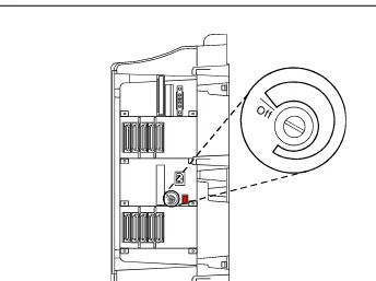
Fan and Filter Removal/Replacement
1. Remove the left door.
2. Remove the fan/filter access panel. See Figure 1-3. DEFINITY csi Preventive Maintenance Log
Date System Installed: _________________________
Component (Comcode)
Scheduled Date
Completed Date
Completed By
Scheduled Date
Completed Date
Completed By
Air Filter1
(407745009)
Maintenance for csi systems
1-19 Preventive Maintenance Procedures
1
Figure 1-3. Fan/Filter Removal
Fan Assembly Removal/Replacement
1. Pull (unplug) the fan assembly from the chassis. The power for the fan automatically disconnects when the assembly is unplugged.
2. Plug in the new fan assembly. The power for the fan automatically connects when the fan assembly in plugged in.
Replace the fan/filter access panel and the left door.
Fan Filter Removal/Replacement
1. Remove the fan access panel from the left side of the cabinet.
2. Pull the fan filter from the chassis.
3. Clean (vacuum or wash with water) or replace the filter as needed and slide the filter back into the chassis.
4. Replace the fan access panel.
scdmfltr RPY 072297
Filter
Maintenance for csi systems
1-20 Initialization and Recovery
1
Initialization and Recovery
When the system is initially powered up, or when an existing system experiences a catastrophic fault that interrupts its basic functions, the system either initializes or reboots.
Initialization
Upon initialization, no forms (not even Customer Options) are available until the Offer Category is set. (The remote INADS channel is available.) To set the customer options (INADS password only), do the following:
1. Enter change system-parameters offer-options (init and inads logins only) and the following form displays:
Field descriptions
2. After these two fields are filled and you press Enter, the system displays:
WARNING: Activating Offer Category may set unchangeable limits.
This is to let you know that the Offer Category along with the model determine the system capacities (limits) and allowable hardware.
3. Select the Submit option to submit the form.
4. Use the save translations command to make the changes permanent.
!
CAUTION:
To avoid potential loss of service, ensure that your system’s translations are protected by saving them to the PCM/CIA card.
Offer category Type either A or B.
Activate offer? Type y if the entry for Offer category is correct and press Tab.
Type n if there is an error in the Offer category field and press Tab. Re-enter the correct Offer Category.
change system-parameters offer-options
OFFER OPTIONS FORM
Offer Category: _ Activate Offer? _
Maintenance for csi systems
1-21 Initialization and Recovery
1
Recovery
There are several less severe resets available to the system that allow it to recover from disrupting errors. The user can initiate these resets by using the
reset system n commands (where n is the reset level). These commands are used to manually restart the system at various levels, depending on the required test activity. The reset system commands are discussed below.
A system is reset due