SAN Storage Switch
GUIDE
InSpeed
TM
Model 375
Vixel InSpeed™ SAN Storage Switch Model 375 User’s Guide Part Number 00041392-001 Rev. A
Copyright © 2003 Vixel Corporation. All rights reserved worldwide. No part of this document may be reproduced by any means nor translated to any electronic medium without the written consent of Vixel Corporation.
Information furnished by Vixel Corporation is believed to be accurate and reliable. However, no responsibility is assumed by Vixel Corporation for its use; or for any infringements of patents or other rights of third parties which may result from its use. No license is granted by implication or otherwise under any patent or patent rights of Vixel Corporation.
Vixel, InSpeed™, and FibreSpy™ are registered trademarks of Vixel Corporation. All other brand or product names referenced herein are trademarks or registered trademarks of their respective companies or organizations. Vixel Corporation provides this manual “as is,” without any warranty of any kind, either expressed or implied, including but not limited to the implied warranties of merchantability or fitness for a particular purpose. Vixel Corporation may make improvements and changes to the product described in this manual at any time and without any notice. Vixel Corporation assumes no responsibility for its use, nor for any infringements of patents or other rights of third parties that may result. Periodic changes are made to information contained herein; although these changes will be incorporated into new editions of this manual, Vixel Corporation disclaims any undertaking to give notice of such changes.
Vixel Corporation, 11911 North Creek Parkway South, Bothell, WA 98011
Table of Contents
1
Introduction ... 1
2
Switch Installation ... 6
3
Switch Management ...15
4
Technical Reference ...57
Appendixes ... 61
A
Specifications ... 62
B
CLI Quick Reference... 63
C
Event Messages ... 66
D
AL_PA Cross References ... 68
E
Glossary ... 69
C
HAPTER
1 I
NTRODUCTION
This guide is designed to provide users with the necessary information to install and manage the Vixel InSpeed™ SAN Storage Switch Model 375 for use in Fibre Channel applications in typical entry-level Storage Area Networks (SANs).
O
VERVIEW
The Vixel InSpeed™ SAN Storage Switch Model 375 is designed for entry-level Storage Area Networks (SANs), which provide the following advantages over direct attached storage:
• Greater application availability
• Higher performance between servers and storage devices • Improved storage asset utilization
• Lower storage management and support costs
• Incremental scalability to keep up with difficult to estimate storage growth
This switch is ideal for storage pooling and consolidation, high-performance shared tape library backup and recovery, server clustering, and streaming rich media applications.
Enclosed in a 1U, full-rack form factor enclosure, the switch is built around the InSpeed™ SOC 320 and is controlled by firmware loaded into the on-board Flash.
The switch is designed as a central interconnect following the ANSI FC-AL standard. Devices are connected to the switch through Small Form-factor Pluggable (SFP) transceivers and cables. Each attached node has 1 or 2 Gigabits per second (Gb/s) of Fibre Channel bandwidth. The switch operates at full switching bandwidth that reaches speeds of 4 GB/s per port and up to 80 Gb/s of aggregate bandwidth.
Complete switch configuration and management is available through the intuitive, graphical-based Web Manager interface. A variety of network configurations are easily established using the switch’s Port Smart Settings, One-Step Zoning, Automatic Trunking, and Load Balancing features. In addition, the switch features granular change notification management, retained system configuration parameters, and a Command Line Interface (CLI) for advanced users.
Overview... 1
Features ... 2
InSpeed™ Technology ... 2
Switch Applications ... 3
F
EATURES
The Vixel InSpeed™ SAN Storage Switch Model 375 has the following features: • High Performance Fibre Channel Switching:
• Wire speed non-blocking Crossbar switch core
• Single 20-port Vixel InSpeed SOC 320 ASIC with embedded SERDES • Multiple simultaneous conversations between ports
• Traffic routed directly to destination ports • 2 Gb/s or 1 Gb/s performance across all ports • Aggregate bandwidth of 80 Gb/s
• Supports cascades up to 3 switches and up to 126 host and storage devices • No complex fabric services or buffers
• Effortlessly connects to any vendor’s fabric • Patent-pending technology:
• Fairness and Prioritization–ensures devices all have guaranteed access, or explicitly have prioritized access, over all other devices in a system. • StealthTM Intelligent Change Manager–delivers maximum stability through
automatic elimination of state and change notification system disruptions and unprecedented control of disruptive events.
• Automatic Trunking–enables fully-multiplied throughput and bandwidth, failover pathing, and dynamic load balancing and device prioritization.
• Advanced diagnostics, performance monitoring, and fault isolation including continuous switch and port monitoring and automatic bypass of problematic or unused ports.
• Port Smart Settings, which are predefined port-level configurations that optimize switch performance and stability.
• One-Step Zoning, including overlapping/non-overlapping zones with port or AL_PA-based zoning.
• Switch management using the embedded http-based web server, Command Line Interface (CLI), or Simple Network Management Protocol (SNMP).
• Full-rack, 1U size for easy installation (optional 19" rack-mounting kits available). • Redundant fans and two hot-swappable, auto-sensing, load sharing, universal power
supplies for high availability.
• Fibre Channel ANSI Standards Compliance
I
N
S
PEED
™ T
ECHNOLOGY
Vixel’s InSpeed™ technology is an advanced switching architecture that couples a non-blocking crossbar switch with a unique switch port logic and per-port SERDES. This results in the industry’s highest density Fibre Channel switch on a chip (SOC). The port logic is based on Fibre
Channel-Arbitrated Loop (FC-AL), an ANSI standard (X3T11) designed to provide shared bandwidth over low-cost media.
S
WITCH
A
PPLICATIONS
The Vixel InSpeed™ SAN Storage Switch Model 375 is ideal for consolidation and shared storage pooling, high-performance shared tape library backup and recovery, server clustering, and streaming rich media applications. The following sections provide examples of these applications.
Storage Consolidation and Shared Storage Pooling
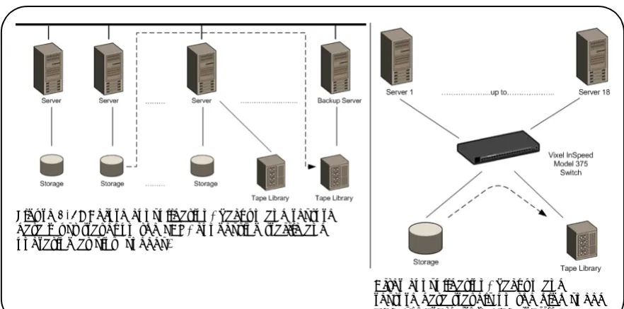
In this configuration, the switch enables multiple hosts to share single or multiple storage systems. This application replaces direct-attached configurations that require multiple storage systems to be attached to separate servers, which often results in difficult to manage multiple systems and trapped, unused storage islands (storage cannot be shared with other servers).
Benefits include:
• Improved incremental scalability–connect up to 20 hosts and/or other storage devices, including tape libraries, to a single switch.
• Lower storage management support costs.
• Improved capacity utilization that enables effective use of both servers and storage. For larger system environments, multiple switches can be connected and Automatic Trunking can be used to keep performance and availability at high levels. As a best practice when using multiple switches, connect servers and their related storage devices through the same switch to optimize performance.
Figure 1-1: Before storage consolidation... and after storage consolidation.
Figure 1-2 depicts a sample multiple switch storage consolidation configuration in which multiple servers communicate with storage devices and zoning is incorporated. The zoning in Figure 1-2 might be set up to configure a multiple operating system environment. For example, Zone 1 might be Windows-based, Zone 2 might be Linux-based, and Zone 3 might be Unix-based. Zoning can also be used to improve security by masking storage devices or files. For example, a finance department could secure financial files from viewing by the engineering department, which in turn could secure engineering files from viewing by the finance department.
Tape Library Consolidation
Another switch application is the consolidation of multiple tape libraries attached to individual servers into a single library for all servers for backup and restore purposes.
Benefits include:
• Improved cost effectiveness.
• Improved availability for performing system backups:
• Off-LAN System Backups often reduce the amount of time it takes backups (and recovery) to occur because SANs run at higher performance bandwidth than LANs. • Server-less backups enable applications to remain fully active during backup and
recovery processes, when combined with the appropriate backup software solution.
Figure 1-3 depicts a sample tape library consolidation configuration.
Figure 1-3: Before consolidation, backup and restore data must travel on the LAN, congesting traffic and operating at slow speeds.
Rich Media
For rich media applications, the switch provides improved storage and file sharing from a single storage pool for multiple workstations.
Figure 1-4 depicts a sample rich media configuration.
Server Clustering
In this configuration, the switch helps deliver improved application availability when combined with a server clustering software solution, like Microsoft Cluster Server or Veritas Cluster Server. This prevents system downtime in case of failure to one of the application servers.
Figure 1-5 depicts a sample server clustering configuration.
Figure 1-4: Rich media diagram
C
HAPTER
2 S
WITCH
I
NSTALLATION
I
NSTALLATION
P
REPARATION
After receiving the switch, perform the following steps to ensure the switch and other contents arrived safely.
To unpack the switch:
1. Inspect the outer shipping container for any damage that may have occurred in shipping. Report any sign of damage to the appropriate shipping agency.
2. Remove the switch and cables from the shipping container; save the shipping container, foam, and antistatic bags—returning the switch in any other container is not advised. Make sure the following parts are included:
• Switch unit
• RS-232 null-modem serial cable • Power cables (2)
• Self-adhesive pads (4)
• Retention clips (2), screws (4), and washers (4) for securing the power cords to the switch.
• Vixel InSpeed™ SAN Storage Switch Model 375 Quick Install Card • Product Release Notes
• Vixel Safety and Regulatory Guide
• Additional documentation, including warranty information and the End User License Agreement.
3. Inspect the switch thoroughly. (If any signs of damage are seen, notify a sales representative and/or the shipping agency.)
Installation Preparation ... 6
Switch Installation ... 7
Switch LEDs ... 9
SFP Compatibility ... 12
Booting the Switch and SAN... 13
S
WITCH
I
NSTALLATION
The switch may be placed on a desktop or installed in a rack.
Desktop Installation
To place the switch on a desktop:
1. Turn the switch upside down so the case bottom is facing up.
2. Install a self-adhesive pad (included) on each corner of the switch bottom approximately 1 inch from each side (prevents surface damage).
3. Turn the switch right-side up so the case bottom is facing down and place the switch on a stable table or platform.
For information on environmental requirements, see “Operating Conditions” on page 62.
Rack Installation
Installing the switch in an equipment rack requires an optional rack mount kit (sold separately). There are two kit variations currently available:
• 24-inch Full Rack Mount Kit (Part Number 00651382), which supports equipment rack depths from 22 to 29 inches.
• 30-inch Full Rack Mount Kit (Part Number 00651383), which supports equipment rack depths from 29 to 36 inches.
The rack mount kit includes all the necessary hardware and installation instructions for properly installing a switch into an equipment rack. Contact a sales representative for more information or assistance in purchasing a kit.
UL Guidelines for Mounting Equipment in a Rack
When installing equipment in a rack, give careful consideration to the following factors: • The operating ambient temperature of rack-mounted equipment must not exceed the
maximum rated ambient temperature, which is indicated in this installation guide. (See “Operating Conditions” on page 62.)
• The air flow clearances specified in this installation guide must be maintained within the rack. (See “Operating Conditions” on page 62.)
• The AC supply circuit for rack-mounted equipment must be capable of supplying the total current specified on all the labels of the rack-mounted equipment.
• All AC power supply connections must be properly earthed. To ensure the integrity of the earth connection, special attention must be given to connections that are not directly connected to the branch circuit (for example, power strips).
• The rack-mounting hardware has been carefully selected to properly support the equipment. Any alternate rack-mounting hardware must provide equal or superior support.
Installing the Retention Clips (optional)
The switch ships with two, optional retention clips to secure the power cords in each power supply/fan module’s power receptacle. Screws (4) and washers (4) are provided for the clips.
To install the retention clip:
1. Secure the retention clip to the switch by aligning the retention clip with the two screw holes located to the left and the right of the module’s power receptacle. The retention clip mounting loops should be facing downward.
2. Place the washer on the screw prior to inserting the screw through the retention clip’s mounting loop.
3. Using a screwdriver, tighten the screws to secure the retention clip to the power supply/ fan module.
To insert the power cord with the retention clip in place:
1. Insert the power cord plug into the module’s power receptacle. The plug must initially be inserted into the receptacle at an angle to avoid the retention clip.
2. Once the power cord plug is firmly inserted in the module’s power receptacle, the retention clip fastens over the end of the power cord plug to secure it in the power receptacle.
To remove the power cord with the retention clip in place:
S
WITCH
LED
S
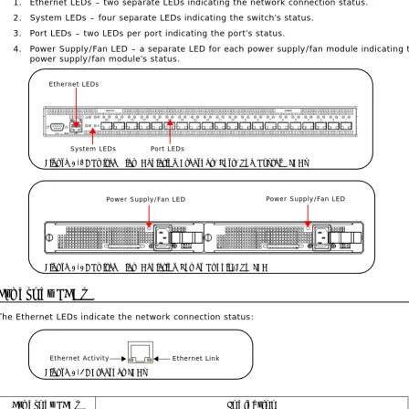
The switch incorporates four sets of Light-Emitting Diodes (LEDs) to indicate ethernet, switch, port, and power supply/fan module status:
1. Ethernet LEDs – two separate LEDs indicating the network connection status. 2. System LEDs – four separate LEDs indicating the switch’s status.
3. Port LEDs – two LEDs per port indicating the port’s status.
4. Power Supply/Fan LED – a separate LED for each power supply/fan module indicating the power supply/fan module’s status.
Ethernet LEDs
The Ethernet LEDs indicate the network connection status:
Ethernet LEDs Indication
Ethernet Activity (green LED)
• When flashing, the ethernet port is receiving data. • When flashing rapidly, the traffic level is high.
Ethernet Link (green LED)
When lit, the switch is connected to an operational ethernet.
Figure 2-1: Switch View Depicting Ethernet, Port, and System LEDs
Port LEDs Ethernet LEDs
System LEDs
Figure 2-2: Switch View Depicting Power Supply/Fan LED
Power Supply/Fan LED Power Supply/Fan LED
Figure 2-3: Ethernet LEDs
System LEDs
The System LEDs indicate the switch’s status, independent of the port LEDs.
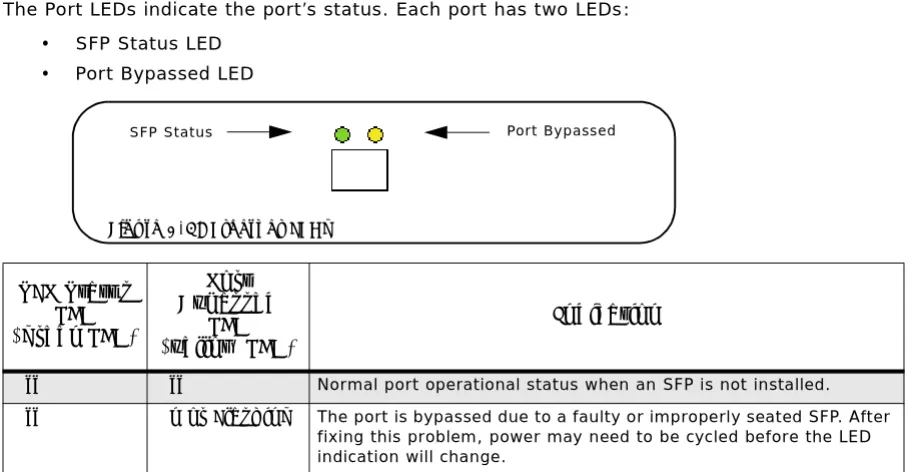
Port LEDs
The Port LEDs indicate the port’s status. Each port has two LEDs: • SFP Status LED
• Port Bypassed LED
System LEDs Indication
Fault
(yellow LED)
• When lit, one or more of the ports has failed or the internal temperature has exceeded acceptable levels.
• When flashing, all ports are operational but another error has occurred. Errors appear in an event log. The level of error severity that will cause flashing to start can be controlled using the configsysfault command in the CLI. The default is level 3, Critical.
Note: Whether lit or flashing, the switch will continue to operate. Switch functionality may be impaired depending on the event that triggered the Fault LED. Regardless of the cause, the switch requires immediate attention.
Power (green LED)
When lit, the switch is plugged in and the internal power supplies are functional.
2 Gb/s (green LED)
When lit, the switch is set to operate at a speed of 2 Gb/s. When off, the switch is set to 1 Gb/s.
Switch Operational (green LED)
• When lit, indicates that the switch has completed initialization for ports with inserted SFPs and that the switch is operational.
• When flashing, the switch has been configured for multiple zones, and one or more zones are up with at least one zone down.
If no zones (excluding hard zones) are operational, the LED turns off.
SFP Status LED (green LED)
Port Bypassed
LED (yellow LED)
Indication
Off Off Normal port operational status when an SFP is not installed.
Off On or Flashing The port is bypassed due to a faulty or improperly seated SFP. After
fixing this problem, power may need to be cycled before the LED indication will change.
Figure 2-4: System LEDs
Power
Switch Operational Fault
2 Gb/s
Figure 2-5: Ethernet LEDs
Power Supply/Fan Module LED
The switch uses two power supply/fan modules to guarantee high availability with failover. Each power supply has a separate LED to indicate its condition.
When a power supply or fan fault occurs, the switch will continue to operate normally as long as the faulty power supply/fan module remains installed in the switch and there are at least two fans operational in each module. If the power supply/fan module is removed from the switch, the switch will continue to operate normally for approximately 20-30 minutes. However, to guarantee continued operation, the malfunctioning module should be immediately replaced to maintain high availability.
Flashing Off Activity. Data is being transferred between the port and device.
On Off Normal operation but no activity. Port and device are fully operational.
On Flashing Manually bypassed. A port can be manually bypassed using the Web
Manager’s Bypass Port feature.
On On Bypassed. SFP is installed but the port is not receiving a valid signal or is receiving an F8 Failure notification from the attached device.
Flashing Flashing Beaconing. This is set manually using the Web Manager or CLI.
Power Supply/Fan Module
LED (green LED) Indication
On No faults exist and AC power is supplied to the module.
Off A power supply or fan fault has occurred in the module.
Note: Keeping spare power supply/fan modules (Part Number 601319) in stock is highly recommended. Contact a sales representative for further information.
SFP Status LED (green LED)
Port Bypassed
LED (yellow LED)
SFP C
OMPATIBILITY
SFPs are “hot-pluggable” into the switch, which allows host computers, servers, and storage devices to be added dynamically without requiring power removal from the switch or any connected devices.
The switch supports Small Form-Factor Pluggable (SFP) modules that comply with the SFP specification as produced by the MSA consortium and have passed Vixel’s qualification testing. The following manufacturers of 1-2Gb optical, shortwave SFPs are recommended:
• Finisar • JDS Uniphase
Contact a customer service representative to request the certified part numbers for these vendors.
Installing an SFP
If the Change Notification on Insertion policy is enabled, plugging an SFP into the switch will automatically send an F7 Initialization notification to indicate the device is ready to begin initialization.
To insert an SFP:
1. Remove dust covers or plugs from the SFPs, if provided.
2. Slide the SFP into the port, ensuring correct polarity, until the latch clicks into place.
Removing an SFP
To extract an SFP:
Determine what kind of extraction mechanism the SFP has and remove the SFP as follows:
If the SFP has a removal tag, remove the cable from the SFP and then pull the removal tag outward and toward the side of the SFP with the tag.
If the SFP has a small plastic slideron the top or bottom, remove the cable from the SFP and then push in the slider and hold while pulling out the SFP.
If the SFP has a bale (small metal clasp), remove the cable from the SFP and then unlatch, pivot, and pull the bale.
Attaching a Device to the Switch
To attach a device:
1. Make sure that the device is FC-AL compatible. 2. Attach a cable to the device.
3. Attach the other end of the cable to an SFP.
4. Make sure that the device and switch are operational and set to the same speed.
B
OOTING
THE
S
WITCH
AND
SAN
The following procedure is recommended when booting the switch and SAN. Before powering on the switch and SAN, read the Release Notes, included with the switch contents, to determine any modifications that may be required for a specific installation.
To boot the switch and SAN:
1. Power on the storage devices (such as JBODs, tape libraries, and RAIDs).
2. Insert the plug end of the switch’s power cord to a properly grounded power source. 3. Insert the power cord’s IEC connector end into the switch’s power receptacle.
The switch powers on and runs Power-On Self-Test (POST) diagnostics to verify the fundamental integrity of the switch ports. All switch LEDs turn on (LEDs illuminate). Then, excluding the Ethernet Link, Power Supply/Fan Module, and Power LEDs, the LEDs turn off (LEDs extinguish). Once the switch is operational, the LEDs display current status as described in “Switch LEDs” on page 9.
4. Power on any other switches connected to the SAN.
5. For certain applications, switch configuration must be completed before continuing with the next step. For information regarding switch configuration, see Chapter 3: Switch Management.
6. After all switches have initialized, power on the hosts. The network initializes.
7. Check all port LEDs.
The SAN should be fully operational at this point. However, it is appropriate to ensure proper discovery has taken place and all required devices are participating in the network. Some host bus adapters may provide this level of functionality or it might be resident in the application software on the host operating system.
Note: The power cord’s IEC connector plug serves as the switch’s disconnect device. To cycle power to the switch, remove and reconnect the switch’s power cord.
P
OWER
S
UPPLY
/F
AN
M
ODULE
R
EPLACEMENT
The Vixel InSpeed™ SAN Storage Switch Model 375 has hot-swappable power supply/fan modules for high availability. A power supply/fan module consists of an individual power supply and a fan bank consisting of three fans.
The switch can run on one functioning power supply/fan module indefinitely, as long as the faulty power supply/fan module remains installed in the switch and there are at least two fans
operational in each module’s fan bank. If the power supply/fan module is removed from the switch, the switch will continue to operate normally for approximately 20-30 minutes. Non-functional modules should be immediately replaced to maintain high availability.
To remove an old power supply/fan module:
1. Have the new power supply/fan module close to the switch for quick insertion. (This step ensures that the procedure takes no longer than necessary—the switch can only operate with one power supply/fan module installed for approximately 20-30 minutes.)
2. Unplug the power cord from the faulty module’s power receptacle.
3. Slide the safety latch over the power receptacle to expose the thumb screw. 4. Loosen the two thumb screws. No tools are required.
5. Pull the unscrewed power supply/fan module out of the switch’s module bay using the module’s handle.
To insert a new power supply/fan module:
1. Align the power supply/fan module with the module bay opening. Ensure the warning label is facing upwards on the module.
2. Carefully slide the module into the opening. Ensure the module is seated firmly in the module bay (the module should be flush with the switch’s face).
3. Tighten the two thumb screws. No tools are required.
4. Slide the safety latch over the thumb screw (uncovering the power receptacle). 5. Plug the power cord into the module’s module power receptacle.
Note: Keeping spare power supply/fan modules (Part Number 601319) in stock is highly recommended. Contact a sales representative for further information.
Note: The alternate power supply/fan module should remain powered on while the faulty module is removed and replaced to guarantee switch availability.
WARNING
To avoid an electrical hazard, never apply power to the power supply/fan module while the module is removed from the switch.
C
HAPTER
3 S
WITCH
M
ANAGEMENT
This chapter is divided into three sections providing information on how to manage and monitor the switch:
• Getting Started – Describes how to configure the network interface, use the Web Manager, and perform a basic initial setup of the switch.
• Managing the Switch - Describes how to configure the switch and port settings, manage firmware versions and configuration files, set switch thresholds, and configure One-Step Zoning, Automatic Trunking, and Load Balancing.
• Monitoring the Switch – Describes how to view switch information, the event log, port information, and port diagnostics.
The switch incorporates two distinct interfaces for managing and monitoring purposes:
• The Web Manager interface provides an intuitive graphical user interface that enables users to quickly check switch status or modify switch settings in a visual environment. • The Command Line Interface (CLI) provides flexibility and additional functionality for
advanced users.
Both of these interfaces provide nearly identical functionality; however, for the purposes of this guide, the Web Manager interface is used for switch and port configuration unless otherwise noted.
For a list of CLI commands, see Appendix B: CLI Quick Reference on page 63. For additional information on the CLI, see the InSpeed Storage Switch CLI Reference Guide.
Getting Started ... 16
Managing the Switch... 21
G
ETTING
S
TARTED
This section explains how to configure the switch’s ethernet network settings prior to using the Web Manager. Once the switch’s network settings are configured, use the Web Manager to perform a quick switch setup.
Configuring the Network Interface
Before using the Web Manager, ensure the switch’s ethernet network parameter settings are correct for the network configuration. The switch ships with the following default IP settings:
• IP Address: 169.254.10.10 • Netmask: 255.255.0.0 • Gateway: 0.0.0.0
To adjust these settings to open the Web Manager, connect to the switch using the provided serial interface cable and follow the instructions below.
To connect through a serial interface:
1. Attach one end of the included RS-232 null modem cable to the computer’s DB-9 serial port and attach the other end to the switch’s DB-9 serial port.
2. Open a terminal session through a serial terminal emulation program (such as
HyperTerminal®) with the appropriate serial port (for example, COM1) and the following serial port parameters:
• Bits per second: 19200 • Data bits: 8
• Parity: None • Stop bits: 1
• Flow control: None
3. If using HyperTerminal, press ENTER to receive a prompt.
If using the tip command on a UNIX workstation, do the following:
a. View the /etc/remote file and create an alias similar to Hardware but with the serial port parameters above. (Suggested name: Switch)
b. Use the tip command to establish a connection through the created alias, for example tip switch. (For more information, see the tip command Manual page.) 4. Type the password at the prompt and press ENTER. (The default password is password.) 5. From the serial terminal emulation program, type config network ip and press ENTER.
The switch’s current IP parameters are displayed with a prompt for entering the IP address.
6. Change the IP address and press ENTER.
7. Use the mask and gateway commands to change the subnet mask and default gateway respectively.
8. Type save and press ENTER.
9. Type root reset and press ENTER.
10. Type y and press ENTER to reset the switch.
11. Attach the computer to the switch’s 10/100 ethernet connector by doing one of the following:
• Attach an ethernet RJ-45 cross-over cable directly between the computer and the switch.
Connecting to the Web Manager
The Web Manager displays current port utilization and health, enables easy to use Port Smart Settings and One-Step Zoning, and several additional features discussed later in this chapter.
To connect to the Web Manager:
1. Ensure the workstation has access to the network on which the switch is connected. 2. Open Microsoft Internet Explorer, version 5.5 or later.
3. In the address bar, type the switch’s DNS name or IP address and press ENTER.
Web Manager Overview
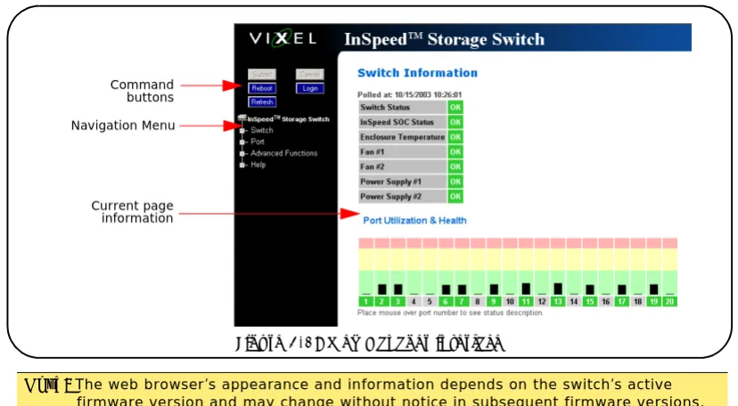
The Web Manager enables users to view and configure switch and port settings using an intuitive, graphical user interface. The main page is the Switch Information page. This page displays general switch status and continually refreshes to display the most current switch status. For more information on the Switch Information page, see “Switch Information” on page 48. To return to this page at any time, click the InSpeed™ Storage Switch menu item.
The Web Manager interface consists of a series of command buttons, an expandable navigation menu, and the displayed information area. The command buttons and navigation menu are always present on the page.
Note: The Web Manager supports the Microsoft Internet Explorer version 5.5 or later web browser on Windows or Apple OS-X operating systems.
Note: The web browser’s appearance and information depends on the switch’s active firmware version and may change without notice in subsequent firmware versions.
Command Button Description
Submit Saves any changes made to the switch configuration. This button is
disabled until a configuration setting is changed or new information is entered. This button appears green to notify the user of a change to the switch configuration. Click this button to accept the configuration change.
Cancel Cancels a request. This button is disabled until a configuration setting is
changed or new information is entered. This button appears green to notify the user of a change to the switch configuration. Click this button to cancel the configuration change.
Figure 3-1: Web Manager interface
Navigation Menu Command buttons
The expandable navigation menu provides several options for configuring and monitoring the switch. The menu uses a tree-based navigation structure with a list of menu options and items. Clicking a menu option with a "+" next to it expands the menu option and displays additional menu items. Clicking a menu item displays the selected Web Manager page.
To ensure that the most current information is displayed, use the navigation menu instead of the browser’s Back and Next buttons, which usually display cached copies and may not reflect current switch information.
To log out of the Web Manager, click Logout, or simply close the browser window.
Documentation
The Web Manager’s Help menu provides links to online product documentation and firmware downloads.
To access product documentation:
1. Click Help > Documentation. 2. Click Product Docs.
A documentation request web page appears.
3. Enter the appropriate information and click Submit Request.
An email message is sent to the provided email address with the web page location for the requested product documentation.
To view Technical Brief documentation, click Technical Briefs.
To download firmware:
1. Click Help > Downloads.
A download request web page appears.
2. Enter the appropriate information and click Submit Request.
An email message is sent to the provided email address with the web page location for the requested firmware download.
Reboot Resets the switch.
Login/Logout Logs in to and out of the switch.
Refresh Redraws the currently displayed web page.
Note: The Web Manager will automatically log users out after 15 minutes of inactivity, unless the Switch Information page is currently displayed. The Switch Information page automatically updates to display the most current switch status.
Initial Switch Setup
Once a network connection has been established with the switch and an instance of the Web Manager is open, some basic switch configuration tasks are recommended:
• Log in to the switch.
• Change the switch’s password.
• Verify the switch’s date and time settings. • Change the switch’s name.
For additional information on Web Manager features and functionality, see “Managing the Switch” on page 21 and “Monitoring the Switch” on page 48.
Step 1: Log in to the Switch
The switch incorporates a password-level security system to prevent unwanted changes to the current switch configuration. In order to make any changes to the switch, users must be logged in to the switch.
To log in to the switch:
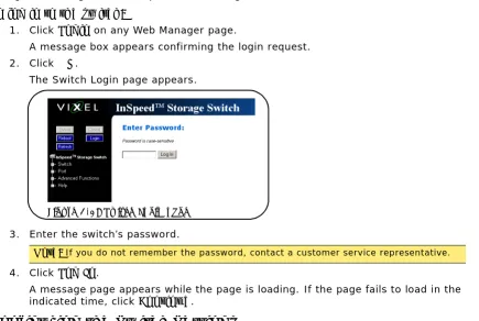
1. Click Login on any Web Manager page.
A message box appears confirming the login request. 2. Click OK.
The switch login page appears. 3. Enter the switch’s password.
The default password is "password". 4. Click Log In.
A message page appears while the page is loading. If the page fails to load in the indicated time, click Continue.
See “Logging in to the Switch” on page 22 for additional information.
Step 2: Change the Password
The default password is set at the factory to "password". Change the default password to secure the switch and guarantee that any configuration changes are only performed by registered users.
To change the password:
1. Click Switch > Password.
The Switch Password page appears.
2. Enter the new password in the New Password text box.
3. Enter the new password again in the ConfirmNew Password text box. 4. Click Submit.
A message box appears confirming the change to the switch’s configuration. 5. Click OK.
The Password set success message appears confirming that the new password was saved and activated.
See “Changing the Password” on page 27 for additional information.
Step 3: Verify the Date and Time
During the initial Web Manager session, the date and time for the switch are set based on the host system’s current settings.
To view the current date and time:
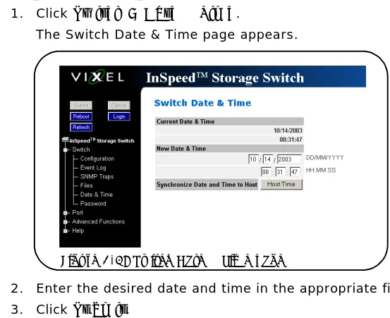
1. Click Switch > Date & Time.
The Switch Date & Time page appears.
To set the date and time settings:
1. Enter the new date and time settings in the appropriate fields. 2. Click Submit.
The new date and time appear under Current Date & Time.
To synchronize the current date and time settings with the host system:
1. Click Host Time.
The date and time of the current host system appear in the New Date & Time text box. 2. Click Submit.
The new date and time appear under Current Date & Time.
See “Configuring Date and Time Settings” on page 26 for additional information.
Step 4: Change the Switch Name
While not required, changing the switch’s name is recommended for identification and troubleshooting purposes.
To change the switch name:
1. Click Switch > Configuration.
The Switch Configuration page appears. 2. Enter the new name in the Name text box. 3. Click Submit.
The new name appears in the Name text box and also appears in the title bar after the "InSpeed™" label.
See “Switch Identification” on page 23 for additional information.
Note: The web page may have to be refreshed before seeing the name change. Press
M
ANAGING
THE
S
WITCH
The Vixel InSpeed™ SAN Storage Switch Model 375 provides several options for managing and configuring the switch to meet the needs of the network environment.
This section describes how to log in to the switch, configure switch and port settings, manage firmware and configuration files, and configure One-Step Zoning, Automatic Trunking, and Load Balancing.
Frequent Switch Configuration Tasks
A list of frequent switch configuration-related tasks is provided below. The list displays the task, the corresponding Web Manager command, and a reference to where more information may be found in this guide.
For information on viewing switch status and information, see “Monitoring the Switch” on page 48.
To… Click… In this guide, see...
View switch status InSpeed™ Storage Switch
“Viewing Switch Status” on page 48.
Change general switch configuration
Switch > Configuration “Configuring the Switch Settings” on
page 22.
Change the IP Address Switch > Configuration “Network Location” on page 23 Change the switch speed Switch > Configuration “Switch Speed” on page 24.
View the event log Switch > Event Log “Viewing the Event Log” on page 50. Configure traps Switch > SNMP Traps “Setting SNMP Traps” on page 25. Upgrade the firmware Switch > Files “Switch Firmware Files” on page 36. Change the Port Smart
Settings
Port > Smart Settings “Configuring the Port Smart Settings” on
page 29. Configure One-Step Zoning Advanced Functions >
One-Step Zoning
“One-Step Zoning” on page 38.
Configure Automatic Trunking
Advanced Functions > Automatic Trunking
“Automatic Trunking” on page 45.
Configure Load Balancing Advanced Functions > Load Balancing
“Load Balancing” on page 46.
Logging in to the Switch
The Web Manager requires users to log in to the switch when changes are made to the switch’s configuration. Log in is not required for viewing switch information.
To log in to the switch:
1. Click Login on any Web Manager page.
A message box appears confirming the login request. 2. Click OK.
The Switch Login page appears.
3. Enter the switch’s password.
4. Click Log In.
A message page appears while the page is loading. If the page fails to load in the indicated time, click Continue.
Configuring the Switch Settings
Several switch configuration settings may be changed to customize the switch to the network environment. To make a change to the current switch configuration, users must be logged in to the switch or know the switch password (the switch prompts users for the password before accepting changes to any configuration settings).
To change a switch setting:
1. Enter new information or make changes to current settings. 2. Click Submit.
The Web Manager page displays the new settings or information.
Changes to certain switch settings require that the switch be reset for those changes to occur. Users must be logged in to the Web Manager to reset the switch.
To reset the switch:
1. Ensure any changes to the current switch configuration have been saved. 2. Click Reboot on the Web Manager page.
The switch will reset.
Note: If you do not remember the password, contact a customer service representative.
General Switch Settings
The Switch Configuration page displays general settings and switch identification information. To view the Switch Configuration page, click Switch > Configuration.
Switch Identification
This section includes general switch identification information.
The name, location, and contact name information may be modified for the network environment. The Serial Number setting is factory set and cannot be modified.
To change the name, location, or contact name:
1. Click Switch > Configuration.
2. Enter the new value in the appropriate text box. 3. Click Submit.
The Switch Configuration page displays the updated information.
Network Location
The switch’s network location is identified by the IP Address, Netmask, and Gateway fields.
Setting Description
Name The name of the switch.
Location The location of the switch.
Contact Name The person or group to contact about the switch.
Serial Number A unique identification number assigned to each switch at the factory.
Cannot be configured or modified.
Setting Description
Ethernet IP Address The current IP Address for the switch.
Netmask The current IP Netmask address for the switch.
Default Gateway The current Gateway address for the switch.
To change the switch’s network location settings:
1. Click Switch > Configuration.
2. Enter the new value in the appropriate text box. 3. Click Submit.
The Switch Configuration page displays the updated information.
Version Information
The different software and hardware versions include:
Switch Speed
The Switch Speed setting indicates the current speed per port at which the switch is running. All ports operate at the same speed. The default switch speed is set to 2.125 Gb/s.
To change the switch speed:
1. Click Switch > Configuration. 2. Select the desired speed.
3. Click Submit.
Blocking ARB
When two ports start a communication session, the Blocking ARB is sent to all other ports trying to communicate with those ports until the connection is terminated. The default setting is "FF". If other connected devices use the "FF" setting for another purpose, select another Blocking ARB value (for example, "FB"). Under normal circumstances, this setting does not need to be modified.
Agent Up Time
The Agent Up Time field displays the duration of time that the switch has been operational. If the switch is rebooted or power is cycled, this value is reset.
The Agent Up Time field is for display purposes and cannot be configured.
Setting Description
MAC ID A unique device address (MAC address) assigned to each switch at the
factory. Cannot be configured or modified.
Switch FW Version The current firmware loaded onto the switch.
Switch HW Version The hardware version of the switch. Cannot be configured or modified.
InSpeed SOC Version The SOC 320 version that is used in the switch. Cannot be configured or
modified.
MIB Version The proprietary Management Information Base version that is supported
through SNMP. Cannot be configured or modified.
Setting Description
1 Gb/s Set switch speed to 1.0625 Gb/s.
Setting SNMP Traps
Simple Network Management Protocol (SNMP) uses traps to transmit information to SNMP-based network administration programs. The Switch SNMP Trap Configuration page displays information on the switch’s current SNMP trap configuration.
To view the SNMP trap configuration page, click Switch > SNMP Traps.
To configure an SNMP trap:
1. Enter the Trap IP address for the device to which the trap information will be sent. 2. Enter the Trap Port number.
This value is usually set to "162" for Windows and Apple-based networks. 3. Select the State.
4. Click Submit.
When editing a registered IP address, delete the current IP address and create a new entry for the revised IP address.
State Description
Active The trap sends messages to the host identified in the IP Address
selection.
Inactive The trap is not operational.
Delete The trap will be deleted from the table once changes are saved.
Configuring Date and Time Settings
The Switch Date & Time page displays the switch’s current date and time. During the initial Web Manager session, the date and time for the switch are set based on the host system’s current settings. If the switch is rebooted or power is cycled, the system clock will reset and the switch’s date and time settings will be set to the host system’s time settings of the next user to log in to the switch.
To change the time:
1. Click Switch > Date & Time.
The Switch Date & Time page appears.
2. Enter the desired date and time in the appropriate fields. 3. Click Submit.
The new date and time appear under Current Date & Time.
To synchronize time with the host system:
1. Click Host Time.
The date and time of the current host system appear in the New Date & Time text box. 2. Click Submit.
The new time appears under Current Date & Time.
Changing the Password
The Switch Password page enables users to change the password for modifying the switch’s configuration. The same password is used to access both the Web Manager and the CLI.
To change the password:
1. Click Switch > Password.
The Switch Password page appears.
2. Type the new password in the New Password text box.
3. Type the password again in the Confirm New Password text box.
4. Click Submit. If users are not logged in to the switch, a password prompt appears requesting that the current password be entered. Enter the current password to proceed. A message displays confirming that the password was saved and activated.
Opening a Telnet Session
Some switch operations may require advanced features currently not found in the Web Manager. These features are available in the Command Line Interface (CLI), which can be accessed through the Web Manager by opening a telnet session to the switch.
To open a telnet session with the switch:
1. Click Advanced Functions > Telnet Session.
A message box appears confirming the opening of a telnet session to the switch. 2. Click OK to proceed.
3. Enter the switch’s password and press ENTER.
For additional information on CLI features and functionality, see the InSpeed Storage Switch CLI Reference Guide.
Note: Until the default switch password is changed, any user with knowledge of the default password can make changes to the switch’s configuration.
Note: The password must be between 6 and 25 characters in length and is case sensitive.
Adjusting the Switch Thresholds
The Switch Thresholds page displays a variety of switch threshold settings.
To view the current threshold settings:
Click Advanced Functions > Thresholds > Switch. The Switch Thresholds page appears.
To change switch thresholds or time intervals:
1. Enter the new value in the appropriate text box. The valid range is displayed next to the text box. 2. Click Submit.
The new value is set.
Setting Description
Ordered Set Error Threshold The maximum number of OS errors allowed in a 10-second interval
before a port is bypassed. Setting this value to "0" returns it to the factory default setting.
This setting is activated on the Port Smart Settings page.
CRC Error Threshold The maximum number of CRC errors allowed in a 10-second interval
before a port is bypassed. Setting this value to "0" returns it to the factory default setting.
This setting is activated on the Port Smart Settings page.
Bad Zone Recovery Hold Time
(measured in centi-seconds)
The amount of time that the switch keeps the ports in bypass mode before attempting to re-insert the ports into the zone.
This setting is activated on the Advanced Functions One-Step Zoning page.
Bad Zone Recovery Delay Time
(measured in seconds)
The amount of time that the switch waits after a zone goes down before attempting to recover the zone.
This setting is activated on the Advanced Functions One-Step Zoning page.
Port Utilization Interval
(measured in seconds)
The length of time between readings of the current port’s utilization.
Configuring the Port Smart Settings
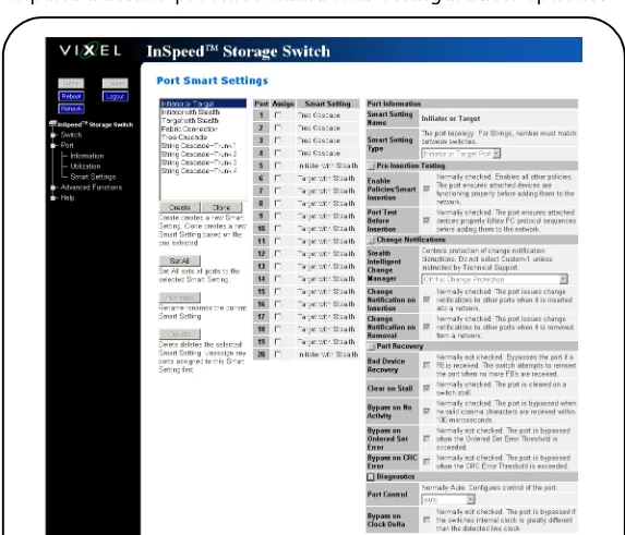
The Port Smart Settings page displays the current Smart Settings (configuration settings) assigned to each port and enables users to easily create and modify custom Smart Settings.
To view the Port Smart Settings page:
Click Port > Smart Settings.
The Port Smart Settings page appears.
Expanding the optional configuration menus on the right-side of the page by clicking the expand buttons provides additional configuration options.
Figure 3-8: Port Smart Settings page
Expand button
Default Smart Settings
There are several default Smart Settings available on the switch. These default Smart Settings were defined by Fibre Channel storage experts to ensure the switch is optimally configured for performance and stability.
The default Smart Settings cannot be modified or deleted, but these settings can be used as templates for creating custom Smart Settings.
Initiator or Target
This Smart Setting is the default setting for all switch ports from the factory. This setting offers no change protection and all settings are set to their default values. Initiators and targets can be connected to ports that are set to this Smart Setting.
This is the recommended Smart Setting for setups with targets and initiators connected to a single switch.
Initiator with Stealth
This Smart Setting is used when connecting a host device to the port. When a port is set to this Smart Setting, change notifications are not sent from the initiator to other devices, but change notifications are received by the initiator.
This Smart Setting is appropriate for embedded storage controllers and external Host Bus Adaptors (HBAs) or servers with installed HBAs.
Target with Stealth
This Smart Setting is used when connecting embedded storage devices, like JBODs, SBODs, tape drives, or external RAID systems (JBODs, SBODs, or tape libraries). When a port is set to this Smart Setting, change notifications are sent to other devices, but change notifications are not received by the target.
Fabric Connection
This Smart Setting is used when connecting a port to a Fabric switch. Only one connection from the Vixel InSpeed™ SAN Storage Switch Model 375 to a Fabric switch is valid.
Tree Cascade
This Smart Setting is used when connecting two or more switches together in a tree configuration. Up to four tree cascades are supported between switches. See “Cascading Switches” on page 44 for additional information.
String Cascade
This Smart Setting is used when connecting two or more switches together in a string
configuration. Up to four string cascades are supported between two switches. See “Cascading Switches” on page 44 for additional information.
Before selecting a cascade option, consider the following:
• Cascade ports of like number should be connected together. For example, connect port 1 of Switch A to port 1 of Switch B, connect port 2 of Switch B to port 2 of Switch C, and so on.
• Cascade port numbers must be lower than non-cascade port numbers (for example, Initiator or Target ports). Therefore, select cascade types before selecting these non-cascade types.
• A maximum of three switches may be connected using string cascades.
• When configuring multiple switches with a single cascade, use alternating ports. For example, connect the second switch using ports 1 and the third using ports 2 as shown in Figure 3-10.
To assign a Smart Setting to one or more ports:
1. Select the appropriate Smart Setting from the list box.
2. From the list of port numbers, select the ports that will use the selected Smart Setting under the Assign heading.
3. Once completed, click Submit to save the settings.
To set all ports to the currently selected Smart Setting:
1. Select the desired Smart Setting from the list box. 2. Click Set All.
3. Click Submit to save the new settings.
Creating Custom Smart Settings
In addition to the default Smart Settings, users can create custom Smart Settings for use in a specific network environment.
To create a custom Smart Setting:
1. Click Create.
A text box appears prompting for the name of the new Smart Setting.
2. Enter the new Smart Setting name.
A name may consist of up to 28 alphanumeric characters and cannot contain spaces (use underscores for spaces in names).
3. Click OK.
The new Smart Setting is added to the list box. 4. Click Submit to save the new Smart Setting.
Note: The Create function always uses the Initiator or Target Smart Setting as the base setting from which to configure a custom Smart Setting.
To create a custom Smart Setting based on an existing Smart Setting:
1. Select a Smart Setting from the list box that most closely matches the port settings that the new Smart Setting should have.
2. Click Clone.
3. Enter the new Smart Setting name.
A name may consist of up to 28 alphanumeric characters and cannot contain spaces (use underscores for spaces in names).
4. Click OK.
The new Smart Setting is added to the list box. 5. Click Submit to save the new Smart Setting.
To modify a custom Smart Setting:
1. Ensure the custom Smart Setting is not currently assigned to a port before making any changes.
2. Select the custom Smart Setting in the list box. 3. Select the new settings.
4. Click Submit to save the new settings.
To rename a custom Smart Setting:
1. Select the desired Smart Setting from the list box. 2. Click Rename.
3. Enter the new Smart Setting name.
A name may consist of up to 28 alphanumeric characters and cannot contain spaces (use underscores for spaces in names).
4. Click OK.
The new Smart Setting name appears in the list box. 5. Click Submit to save the change.
To delete a custom Smart Setting:
1. Ensure the custom Smart Setting is not selected or currently in use. 2. Select the custom Smart Setting in the list box.
3. Click Delete.
4. Click Submit to save the settings.
Smart Setting Assignments
The Smart Settings are based on several port settings grouped into the following categories: • Port Information
• Pre-Insertion Testing • Change Notifications • Port Recovery • Diagnostics
Port Information
The following settings are available.
Pre-Insertion Testing
The following settings are available.
Setting Description
Smart Setting Name Displays the name of the Smart Setting. The Smart Setting name will
automatically appear in the text box when selected in the scroll menu.
Smart Setting Type The topology among switches for a port. Options include:
• Initiator or Target Port – the default setting. Should be used when there are no links between switches.
• Tree Cascade – designates the port as a tree cascade port. Use this setting when connecting multiple switches together in a tree cascade configuration. Under most conditions, this setting will result in acceptable performance.
• String Cascade 1 through String Cascade 4 – designates the string cascade to which a port is assigned. String cascades maintain fairness when two or more InSpeed-based storage switches are serially cascaded. Switch performance may be lower when compared to a tree cascade configuration.
Setting Description
Enable Policies/Smart Insertion
This policy is the default operating mode for all ports and determines what the switch looks for prior to allowing a port to insert into a zone. When the policy is enabled, an external device is sent an F7
Initialization notification by the switch until an F7 Initialization notification is received from the device. Once an F7 Initialization notification is received, the port is inserted in the zone.
This policy takes precedence over all other policies. When this policy is disabled, no additional policies are operational, and as long as a port transmits a signal of the correct frequency and amplitude, the port will be allowed in the zone.
Port Test Before Insertion This policy ensures a device on a port is a valid, standards-compliant
Change Notifications
The following settings are available.
Port Recovery
The following settings are available.
Setting Description
Stealth Intelligent Change Manager
Stealth Intelligent Change Manager provides stability and control over change notification disruptions on a port basis. Options include: • Off: No Change Protection – no Stealth Intelligent Change Manager
control.
• Initiator: Only Receive Changes – devices attached to the port can receive change notifications but will not propagate change notifications generated by that port to other ports.
• Target: Only Send Changes – propagates change notifications
generated by the port to other ports but will not allow devices attached to the port to receive change notifications from other ports.
• Switch-Switch: Send and Receive Changes – allows change notifications to propagate between switches.
• Custom-1 – Note: This setting should not be used unless directed to do so by a customer service representative.
Change Notification on Insertion
The switch normally operates under the condition that when a device is inserted onto the network, a change notification is generated. However, this condition is not always true when connecting hubs or switches together. In some instances, it is possible to connect two zones together without the zones realizing that multiple AL_PAs exist with the same values.
When this policy is enabled, the switch always generates a change notification to ensure the proper system updates are performed. However, when a device is removed (for example, an initiator or target), the removal does not generate a change notification and there are no system updates performed.
Change Notification on
Removal
This policy is similar to the Change Notification on Insertion policy, except for the change notification being sent when a device is removed rather than inserted.
When this policy is enabled, the switch always generates a change notification to ensure the proper system updates are performed.
Setting Description
Bad Device Recovery When a port is already inserted into a zone, the port transforms F8
Failure notifications into F7 Initialization notifications. When this occurs, the port is bypassed and F7 Initialization notifications are allowed in the zone. Once the initialization is complete, the Bad Zone Recovery Policy is operational and prevents a port that continues to transmit F8 Failure notifications from inserting into the zone.
Note: If this policy is disabled while the Bad Zone Recovery policy is enabled, a zone that does go down will still allow the Bad Zone Recovery policy to reset the zone and allow ports to be reinserted.
When enabled, this policy prevents devices that send F8 Failure notifications from inserting into a zone. The ability to remove devices that generate F8 Failure notifications automatically and
Diagnostics
The following settings are available.
Clear on Stall In situations where the switch is operating in switching mode, some
devices may fall into an operating mode where the device has opened a target but has not released the connection to the target. When this policy is enabled, the switch can detect this condition and
automatically recover when this situation arises.
Bypass on No Activity The switch detects the amount of time a data stream has gone
without receiving a comma. The time setting is set to 100 (.001 seconds). When this policy is enabled, the switch bypasses the disruptive port when the threshold is exceeded.
Bypass on Ordered Set Error Ordered Set (OS) errors are detected and counted for each individual
port. When this policy is enabled, a port is bypassed when its OS count exceeds the threshold setting. The threshold setting is based on the number of ordered set errors identified in 10 seconds.
Note: This threshold setting can be adjusted on the Web Manager’s Advanced Functions Switch Thresholds page.
Bypass on CRC Error Cyclic Redundancy Check (CRC) errors are detected and counted for
each individual port. When this policy is enabled, a port is bypassed when its CRC count exceeds the threshold setting. The threshold setting is based on the number of CRC errors identified in 10 seconds. User intervention is required to return the port into the zone. Recovery methods include replacing the defective component, cycling power to the device on the port, removing and reinserting the bypassed port, or cycling power to the switch.
Note: This threshold setting can be adjusted on the Web Manager’s Advanced Functions Switch Thresholds page.
Setting Description
Port Control The method for controlling a port. Options include:
• auto – the default setting. The switch will automatically insert a port based on policy settings. This prevents the insertion of incompatible ports, which may cause disruption.
• bypass – removes a port from the network. Use this mode to keep a device out of an initialization cycle when troubleshooting.
• extLoopback – removes a port from the network and routes the port's receive signal back through the port's transmitter. Use this mode to isolate a specific zone for troubleshooting or to test a transceiver’s circuitry and attached media from the node end. • insert – allows ports whose transceivers cannot derive a valid clock
or "K" character (Ordered Set) to join a zone. Use this mode cautiously – devices without valid characters may put bad data into a zone, causing the zone to go down.
Bypass on Clock Delta The switch determines the relative frequency of the signal being
received by a port to the internal switch clock. The result of this test allows the determination of how far apart in frequency the switch’s clock is in relation to the clock of the received signal – the clock delta. If the clock delta exceeds a set threshold, the switch is notified and the port may be bypassed if necessary. Typically, clock drift is slow enough to allow the removal and replacement of a defective part before the defective part begins to affect system performance.
Managing Firmware and Configuration Files
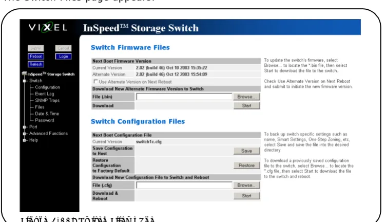
The Switch Files page displays information on the switch’s firmware and configuration files. To view the firmware and configuration files, click Switch > Files.
The Switch Files page appears.
Switch Firmware Files
This section displays the current and alternate firmware versions, enables users to select which firmware version to run the next time the switch is reset, and provides a means to load new firmware on the switch.
To view or download the latest switch firmware, click Help > Downloads. The Web Manager will display the firmware request page. Enter the requested customer information and an email with the location of the appropriate firmware download page for the switch will be sent to the specified email address. If necessary, download the latest switch firmware to the host system.
To load new firmware on the switch:
1. Under Download New Alternate Firmware Version to Switch, enter the directory path and the specific file name in the text box, or click Browse to navigate to and select the appropriate file on the host system. The file must have a .bin extension.
2. Click Start to load the new firmware image.
Once the firmware has been installed, the new firmware should appear as the Alternate Version firmware.
3. Under Next Boot Firmware Version, ensure the UseAlternate Version on Next Reboot
option is selected. The alternate firmware version currently displayed will be loaded on the next boot cycle.
4. Click Reboot to reset the switch using the selected firmware.
Note: When loading new firmware on the switch, clear the web browser’s cache and files to ensure the removal of the older firmware information. In Internet Explorer, use the key combination CTRL+F5, or select Tools > Internet Options and click Delete Files.
To select the alternate firmware version for the next boot:
1. Under Next Boot Firmware Version, select UseAlternate Version on Next Reboot. The alternate firmware version currently displayed will be loaded on the next boot cycle. 2. Click Submit.
3. Click Reboot to reset the switch.
Switch Configuration Files
Switch configuration settings (for example, zoning or Port Smart Settings) can be saved for backup purposes or for loading the same configuration on multiple switches.
To save the current configuration:
1. Click Save to save the current switch configuration. 2. Click OK on the File Download dialog box.
3. Enter the directory path and file name, being sure to use a .cfg extension. 4. Click Save.
To load a saved configuration:
1. Under Download New Configuration File to Switch and Reboot, enter the directory path to the .cfg file in the text box, or use the Browse button to navigate to the appropriate file. 2. In the Choose File dialog box, navigate to and select the appropriate file and click OK. 3. Click Start.
A message box appears confirming the download and required switch reset. 4. Click OK to proceed.
Restoring the Factory Default Settings
If necessary, the switch settings can be reset to their factory default values; however, the network configuration and port type settings are retained.
To restore the factory default configuration:
1. From the Restore Configuration to Factory Default section, click Restore. A message box appears confirming the request.
One-Step Zoning
Zoning allows ports to be divided into multiple virtual zones (or work groups), similar to Virtual Local Area Networking (VLAN). By separating activity on the network, zoning also eliminates change notification propagation (change notifications that occur within one zone cannot propagate to other zones.)
Use zoning to:
• Separate different operating system environments.
• Temporarily block or grant access during backup or other tasks. • Consolidate equipment logically.
• Designate closed user groups for increased security.
• Separate test or maintenance areas from production areas.
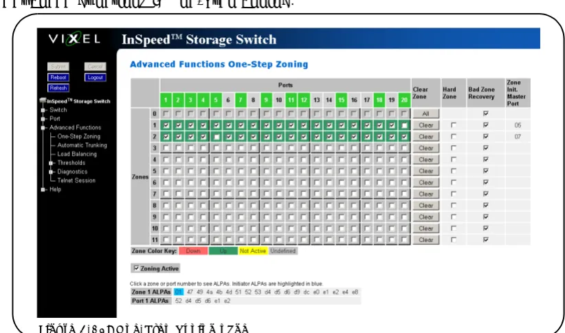
Zone configuration settings are available on the Web Manager’s One-Step Zoning page. The page is arranged as a grid of check boxes for placing ports in appropriate zones. Ports are listed across the top of the grid. Zones are listed down the left side.Similar to other Web Manager pages, the port color represents the current port status.
To view the One-Step Zoning page:
Click Advanced Functions > One-Step Zoning.
The switch is capable of up to twelve zones. Initially, all ports reside in Zone 0. However, a port will clear from Zone 0 whenever it is selected and placed in another zone.
The color of each zone indicates its status. See the descriptions in the following table:
Color Description
Down (red) One or more ports have been selected, zoning has been activated, but
hardware has caused a failure.
Up (green) Ports have been selected, zoning has been activated, and the FC-AL
circuit is operational.
Not Active (yellow) Ports have been selected but zoning has not been activated.
Undefined (gray) No ports have been selected.
The Zone Initialization Master Port field displays the port number of the port that is currently assigned as the master for that particular zone. The Initialization Master is responsible for starting the change notification process in each zone.
To add ports to a zone:
1. Select the appropriate check boxes to place ports into zones. 2. Click Submit.
To activate zoning:
1. Select the Zoning Active check box near the bottom of the page.
2. Click Submit.
To remove a port from a zone:
1. Clear the appropriate check box. 2. Click Submit.
To remove all ports from a zone:
1. Click Clear at the end of the row of check boxes for the appropriate zone. 2. Click Submit.
To remove all zones:
1. Click All under the Clear Zone heading. 2. Click Submit.
Single-Switch Zoning
The simplest zoning configuration is to place each port into a single zone, so that zones are separate from each other as shown in Figure 3-13.
In Figure 3-13, zone 1 includes ports 1, 3, and 4, while zone 2 includes ports 2 and 5. Device