*
Corresponding author: basistag@agh.edu.pl
Experimental and numerical studies of rotating drum grate
furnace
Grzegorz Basista1,*, Mateusz Szubel1, Mariusz Filipowicz1 , Bartosz Tomczyk , and Joanna Krakowiak
1 AGH University of Science and Technology, Faculty of Energy and Fuels, al. Mickiewicza 30, 30-059 Krakow, Poland
Abstract. Waste material from the meat industry can be taken into account as a biofuel. Studies confirm, that calorific value is higher and ash content is lower comparing to some conventional fuels. EU directives regulate details of thermal disposal of the waste material from the meat industry - especially in range of the process temperature and time of the particle presence in area of the combustion zone. The paper describes design of the rotating drum grate stove, dedicated to thermal disposal of the meat wastes as well as solid biomass (pellet, small bricket, wood chips) combustion. Device has been developed in frames of cooperation between AGH University of Science and Technology (Krakow, Poland) and producer focused on technologies of energy utilization of biomass in distributed generation. Results of measurements of selected operational parameters performed during startup of the furnace have been presented and discussed. Furthermore, numerical model of the combustion process has been developed to complement experimental results in range of the temperature and oxygen distribution in the area of the combustion chamber. ANSYS CFX solver has been applied to perform simulations including rotational domain related with specifics of operation of the device. Results of numerical modelling and experimental studies have been summarized and compared.
1 Introduction
Waste material from the meat industry is characterized by a high content of organic matter, from 50%, to almost 80%. This is extremely important for the natural environment, due to bacterial and epidemiological risk [1]. Due to this fact, mentioned wastes should be disposed of as soon as possible, to avoid problems resulting from their storage [2].
There are many ways to exploit various types of waste from the meat industry. They are used in the production of fertilizers, animal feed and the pharmacological and cosmetic industry [3]. However, some components of wastes cannot be processed in any ways, so they have to be utilized [4].
From the energy industry point of view, waste material from the meat production can be used as a biofuel [5]. Due to the necessity of increasing the contribution of renewable energy sources (RES) in the national energy balance, this fact could be important for many countries of European Union (EU). An additional advantage of using meat wastes as a fuel are savings, which result of using a heat of incineration process [6].
Conditions of thermal utilization of this type of wastes are strictly regulated by EU directives 89/369/EEC, 94/67/EC and 2010/75/EU. They define some legal regulations, as well as the specific details of combustion process. Gas temperature behind the last point of air supplying should be at least 850°C for
at least 2 seconds, with a minimum oxygen content of 6% [7]. Also a content of organic compounds (defined as a total content of carbon) and carbon monoxide (CO) are regulated [8]. Thermal devices for meat waste utilization should therefore be designed to meet mentioned regulations.
The required temperature of 850°C has to be kept on the same level during whole process of combustion. Furthermore, dedicated fuel feeder, which will provide material only in case of sufficient enough temperature in the combustion chamber is also necessary. Each decrease of temperature increases risk of incomplete combustion. All above mentioned facts are reason of necessity to use stoves designed and constructed in specific way. Usually combustion is performed in devices equipped with rotating drum grate. During rotation material is combusted, but also crumbled, warmed, dried and pyrolised. In case of fats combustion, temperature of the process in regions near to the stove walls can be higher than 1000°C [9]. Due to the high intensity of pyrolysis it is necessary to apply appropriate air staging system. Dynamic control of the operation of this system provides high efficiency of oxidation of components of the gas in the combustion chamber.
Virmond et al. [10] performed studies of possibility of using biosolids originating from the wastewater treatment process of two meat processing plants, as an alternative fuels. The authors performed an analysis of fuels properties, and the emissions during
combustion in the pilot scale cyclone combustor. Measured lower heating value of some of the investigated fuels was about almost 26 [MJ kg-1, daf]. Temperature of combustion during the test in cyclone combustion was between approximately 750 and 1200°C. The concentration of CO, CO2, CxHy and total organic carbon during the test remained below the limits of strict German regulations for waste incineration. As a main result, the authors have found, that the tested fuels have a high potential for energetic use.
Numerical modelling with CFD methods is a useful tool for advanced design process. It allows to predict some characteristics of combustion process inside the combustion chamber, that cannot be investigated with any experimental methods [11-13].
Ariyaratne et all. [14] have investigated process of meat and bone meal (MBM) combustion in a cement rotary kiln, using a three-dimensional, steady state CFD model. The authors have carried out set of simulations, to find out an effect of various fuel feeding positions and fuel particle size for combustion characteristics. Coal was used in a study as a reference fuel. As a result of the simulations, it was found, that MBM combustion gives a lower gas temperature than coal combustion. This is due to the some parameters of the waste-derived fuel, such as higher moisture and ash content, and lower oxygen content compared to the coal. Lower particle size and temperature in MBM combustion process results also in poor char burnout, but due to the low content of fixed carbon, the impact on gas temperature is insignificant.
2 Test stand
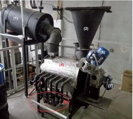
The main element of test stand was patented ceramic rotational furnace, designed specifically to thermal utilization of organic wastes from meat industry. It is designed to keep required conditions during the combustion process. The system consists also: heat exchanger at the chimney, two screw feeders driven by electric engines, twelve independent fans of air supply system, electric igniter, three thermocouples, power supply and a control system equipped with PLC controllers.
Fig.1 Cross section of combustion chamber: (1) ceramic material, (2) insulation, (3) metal cover, (4) gas exhaust, (5) fuel inlet, (6) rotational grate, (7) electric igniter, (8) ash outlet, (9) place of thermocouple installation.
Furnace is constructed of three layers (Fig. 1). Internal layer, which is exposed to high temperatures, is made of ceramic material. External layer is a metal cover, and there is also insulation between cover and ceramic material. Rotational grate is placed inside the combustion chamber. It transports the fuel and ash along the furnace, to ash settling. To provide accurate conditions of combustion process, and continues operation in required temperature range, air is supplied by twelve independent ducts, located at both sides of furnace. Each of these pipes has individually controlled fan.
Fig.2 General view of test stand: (1) heat exchanger, (2) tank of fuel, (3) flue pipe, (4) furnace, (5) chimney, (6,7) electric engines, (8) fans of air supply system.
Gas exhaust is located under the ash settling. Heat exchanger with water jacket is located at the flue pipe, due to high temperature of exhaust gas. Fuel is supplied by the feeder located at the top of furnace, at its beginning part (Fig. 2). Combustion process is initialized next to first air duct.
Fig. 3 Thermocouple no 2. Measuring points are marked at red color.
information about temperature inside the combustion chamber.
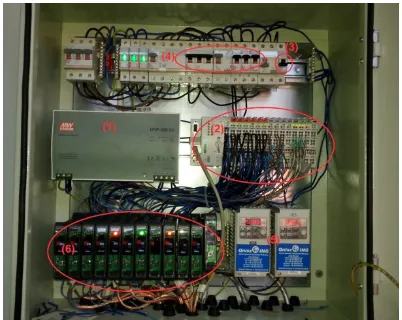
The supporting electric system includes inverters controlling engines of rotational grate and screw fuel feeder, igniter switch, power supply, and control modules for each of air fans.
Fig. 4 Switch cabinet: (1) power supply, (2) control modules, (3) igniter switch, (4) fuses, (5) inverters, (6) fan controllers.
Operation of devices and data acquisition system are controlled using programmable logic controllers, which transmit control signals to inverters and suppliers of air fans. This system is placed in switch cabinet (Fig 4.).
3 Experimental and numerical research
3.1 Experimental tests
The aim of presented study was to analyze the combustion process in a ceramic rotational furnace. The main subject was an examination of temperature distribution in combustion chamber of the device, to achieve the conditions required for thermal utilization of wastes of meat industry.
Biomass pellets with calorific value about 18 MJ·kg-1 and low ash content was used as a fuel. The granulated form of fuel was an additional advantage for combustion process in the device, due to an easy application using a screw feeder. Studies with some conventional type of fuel was necessary to get operational characteristics of device before using organic wastes.
At the first stage of research, the ignition process and the way of controlling of the air supply system were investigated and analyzed. Suitable amount of the fuel at the beginning of the combustion process as well as the rate of the feeding during the process were selected. Firstly, the series of measurements aimed to achieve the highest temperature in the combustion chamber were made. However, it was necessary to take into account a resistance to high temperature of materials used to construction of some elements of prototype. The following measurement series were focused at keeping a proper characteristics of combustion process in required conditions, with 850 Celsius degrees.
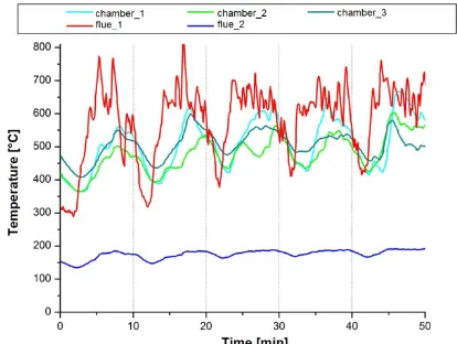
Fig 5. shows the chart of temperature distribution in combustion chamber, and flue gas temperature, during
the first measurement series. It was investigated to analyze an influence of rotational grate operation on combustion process. Rotating of the grate was periodic, as well as fuel feeding. Full turn of the grid on both sides have lasted for 25 to 30 seconds, and was performed every 3 minutes. Fuel in amount of 480 grams was delivered in a two-minute intervals. Rotation of the grid resulted in a rapid rise of temperature in the combustion chamber, as can be seen in the graph as a group of peaks at all measurement points. After reaching the maximum local temperature levels due to rotation of the grid, there were significant decreases of temperature (even almost 200°C). Movement of the grid results in a better mixing of the fuel with the air, and prevents the deposition of ash on the bottom of the combustion chamber. It causes better access of an oxygen to the unburned fuel particles and results in a greater level of post-combustion of these particles. Due to this fact, also temperature value is higher during the rotation of the grid, what can be seen on the graph at Fig. 5.
Fig. 5. Temperature value at five points during the first
measurement series
The maximum temperature value in the first measurement series in the point no. 2 was 900°C, while in the point no. 1 slightly exceeded 1000°C. The temperature of the exhaust gases before the heat exchanger was oscillating from 600°C to 900°C. Due to the limitations of the materials (not insulated regions), after reaching mentioned thermal conditions, between 30 and 35 minute of the process, it was necessary to temporarily suspend delivering of the fuel, to slightly decrease temperature at flue gas exhaust. Due to the fact, that the furnace is still under the research process, the design of both the furnace and the flue is not adapted to operation at temperatures exceeding 1000°C. Operation of heat exchanger have allowed to decrease flue gas temperature to the level about 300°C.
During the first measurement series, the expected temperature of 850°C in the combustion chamber have occurred for 10 minutes, so the first objective has been achieved. Moreover, the impact of the rotation of the grate to the combustion process has been investigated, and some data has been collected.
combustion chamber. The mass flow of the air, as well as the amount of the fuel, was the same as in the first series. However, the time between the turns of the grate was shortened to two minutes. The turn of the grate was performed immediately after the delivering of the fuel.
Fig. 6. Temperature value at five points during the first
measurement series
Figure 6 shows temperature values at five points during the second measurement series. In this case, the value of temperature at measurement point no. 2, located nearby gas exhaust, next to the last stage of air supply system, was significantly higher than in first series.
In the second measurement series, the required conditions (temperature exceeding 850°C) have persisted much longer than in first series – from 30 to 60 minute of the process, which is the entire main phase of combustion process. Similarly to the first series, firing up the furnace has lasted about 25 minutes, while blanking started in 60 minute. It was caused by the increase of the flue gas temperature above 1000°C. Due to the mentioned before material limitations, after reaching temperature of 1000°C in combustion chamber at 40 minute of the process, the amount of the fuel was reduced by half, to 240 grams every two minutes.
Just as in the first measurement series, periodic rotation of the grate directly affected the large temperature fluctuations (most of all the flue gas temperature). However, the effect of shortening the time between turns of the grid is noticeable. This procedure has allowed achieving significantly higher temperature. The increase in number of rotations of the grate resulted in the shift of reaction zone to the further part of combustion chamber, what can be identified with the temperature curve of measurement point no. 1. The values of these temperature during the entire process was lower comparing to first measurement series. As a result of movement of the grate, the fuel was constantly transferred to the end part of the furnace. Due to this fact, higher temperature has occured at the required region, nearby the gas exhaust, after the last stage of air supplying system.
The first part of the research has shown, that it is possible to achieve temperature conditions required to safe incineration wastes of meat industry.
By appropriate controlling, it was possible to maintain required conditions during the main part of the combustion process at the second measurement series. On the base of obtained results, it can be concluded, that after the adaption of the furnace to the higher temperature (using appropriate insulation and materials), it will be possible to exceed the temperature of 1000°C, and maintain these conditions for a longer time. In the existing device, excessive temperature growth has forced to interrupt the process, due to the risk of damaging some parts of the device. However, temperature curves at this points have shown, that the temperature should continue to grow.
To provide efficient and effective operation it is also necessary to develop appropriate algorithms of combustion controlling – for both rotating grate and the fuel feeder. The results show, that more stable conditions of combustion process can be achieved by shortening the length of periods between rotations of the grate, so it can be concluded, that continuous operation would be the most efficient. Due to limited ability of controlling of a grate operation, it was not possible at this stage of research, so it was not examined. The next stage of research was focused on maintaining the operating conditions for a longer period of time.
Fig. 7. Temperature value at five points during the first
measurement series
3.1 Numerical simulation
To identify in more detailed way the characteristic of combustion process on investigated combustion chamber, the three-dimensional CFD model has been developed. A steady-state simulation has been prepared and solved using ANSYS CFX solver. The main purpose of the simulation was investigation of influence of location of air feeding system nozzles and grate rotation, on local temperature and turbulence level. As a first stage of modeling, some simplifications has been applied. The numerical model includes only homogenous gas-phase reactions.
Fig. 8. Computational domain
The computational domain has been defined as a continuous fluid filling the combustion chamber of tested device. The domain was divided into two parts (Fig. 8.). The central region was defined as a rotational domain.
Numerical model is based on CFD governing equations, which include continuity, momentum and energy equations. The “k-” turbulence model has been applied. Combustion process was simulated using „Eddy Dissipation” with “Finite Rate Chemistry” model. It is based on two different mechanisms of combustion, including the rate constant of chemical reactions and level of components mixing. The rate constant is defined by Arrhenius equation:
k = A·exp[-Ea·(RT)-1] (1)
k - rate constant,
A - pre-exponential factor, Ea - activation Energy [7],,
R - universal gas constant [J·mol-1·K-1],
T - temperature [8]
The numerical model have considered only homogenous combustion in gas phase, excluding gasification process of solid fuel. The set of chemical reactions was implemented based on [15]:
CO + 0,5 O2o CO2 (2) CO2o CO + 0,5 O2 (3) H2 + 0,5 O2o H2O (4) CH4 + 1,5 O2o CO + 2 H2O (5) NH3 + O2o 0,5 H2 + H2O + NO (6) NH3 + NO o 0,5 H2 + H2O + N2 (7) HCN + O2o CO + 0,5 H2 + NO (8) HCN + NO o CO + 0,5 H2 + N2 (9)
The material of the computational domain was reacting mixture of all chemical compounds involved in reactions described in (2-9), and inert gas - nitrogen Heat transfer has been described with convection mechanisms. On this early stage of modeling, radiation model and heat transfer through the external walls was not included.
Set of boundary conditions has been defined in computational domain (Fig. 9). The first one was inlet of reacting mixture to combustion chamber. It was placed on the front wall of furnace (INLET_FUEL). This surface has been selected as an inlet to describe combustible gases flow into computational domain in the most accurate way. Mass flow of combustible gases was set to 0,025 kg/s, and it’s temperature was 800°C. The compounds of reacting mixture was: methane (CH4), CO, carbon dioxide (CO2), hydrogen (H2), water vapor (H2O), hydrogen cyanide (HCN), and ammonia vapor (NH3).
Fig. 9. Locations of boundary conditions
The next boundaries were air velocity on the all of 12 inlets to combustion chamber (INLET_R1 – INLET_R6, INLET_L1-INLET_L6). The value was 10 m/s in each case. It has been defined according to the conditions obtained at experimental stand, described at the first part.
As it was mentioned before, the radiation model as well as heat transfer by conduction through the walls has not been considered. The external wall has been defined as an adiabatic wall. Due to this fact, temperature obtained in computational process are slightly higher than real values.
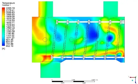
As a result of the simulation, a series of data relating to operation of examined device has been analyzed. Figure 10 shows the temperature distribution at cross section of combustion chamber. An influence of turbulence coming from both, side air feeding, and rotation of the grid, on the temperature in combustion chamber can be observed. At the central region of combustion chamber, in points of temperature measured during the experimental tests, the temperature values obtained on numerical model ranges between about 600°C and nearly 1500°C. There are some zones in initial part of combustion chamber with lower temperature, not exceeding 600°C. However, appropriate conditions nearby flue gas outlet have been achieved, what is the most important due to legal regulations. Average temperature on this region was about 1200°C. This demonstrates a high potential of the device in case of meat waste incineration, even taking into account some inaccuracy of numerical model.
Conclusions
As a subject of the research, a pilot small-scale installation for meat waste thermal utilization has been tested, to obtain required temperature level. The studies were carried out at the test stand with rotational drum grate furnace. Simultaneously, the numerical model has been prepared. The main purpose of the numerical simulations was analysis of processes occurring inside the combustion chamber, which is not possible using experimental methods.
Experimental test were carried out using biomass pellets, characterized by similar to meat wastes calorific value. It allowed to obtain similar conditions of combustion process without using harmful fuel in not tested device.
As a result of experimental tests it was found, that the design of tested device allows to carrying out the combustion process on required conditions, with temperature exceeding 850°C.
Based on the collected data it was also found, that appropriate conditions can be maintained in the case of continuous operation of the device. Adverse influence of both periodic delivering the fuel and periodic rotation of the grate on temperature values has been noticed. They have resulted in huge fluctuations of temperature, and some decreases below required values.
The numerical model describing processes occurring inside the combustion chamber has confirmed the results of the experimental studies. The model has also indicated the possibility of obtaining higher temperature values, which was not possible during the experimental tests at the current stage of research, due to material limitations in some regions of the device.
As the first stage of research has indicated a high potential of the device for meat waste incineration, it is planned to carry out the next, more advanced stage of research. Providing a possibility of continuous operation of the device by modifying the fuel feeding system, the use of sensors adapted to operation in high temperature, and carrying out the measurement
of emissions of particular chemical compounds (primarily CO) would be included. However, the most significant step would be use of meat waste as an addition for biomass fuel under appropriate conditions. It will require also installing an additional burner.
The numerical model will also be developed in the next stage of research. All heat exchange mechanisms should be included, with radiation model inside the computational domain as well as on external walls. More suitable combustion model with developed chemistry kinetics will be applied. Boundary conditions would also be adapted. Both mass flow and composition of the fuel delivered to the combustion chamber would be calculated using experimental data. Important stage of the numerical model would be a calculation of residence time of the fuel particles in the combustion chamber on required temperature.
Acknowledgment
This study was carried out under the “BioORC: Construction of cogeneration system with small to medium size biomass boilers” project.
References
1. F. Toldra, M. C. Aristoy, L. Mora, M. Reig, T, Meat Sci., 92, 290-296, (2012)
2. W. Russ, R.M. Pittroff, Crit. Rev. Food Sci., 44, 57-62, (2004)
3. U. Rahman, A. Sahar, M. A. Khan, Food Res. Int., 65, 322-328, (2014)
4. E. Cascarosa, A. Boldrin, T. Astrup, Waste. Manage. 33, 2501-2508, (2013)
5. L. Fryda, K. Panapoulos, P. Vourliotis, E. Pavlidou, E. Kakaras, Fuel, 85, 1685-1699, (2006)
6. K. Jayathilakan, K. Sultana, K. Radhakrishna, A.S. Bawa, J Food Sci., 49, 278-293, (2012)
7. Council Directive 94/67/EC of 16 December 1994 on the incineration of hazardous waste
8. Directive 2010/75/EU of the European Parliament and of the Council of 24 November 2010 on industrial emissions
9. C.G. Soni, Z. Wang, A.K. Dalai, T. Pugsley, T. Fonstad, Fuel, 88, 920-925, (2009)
10. E. Virmond, R. L. Schacker, W. Albrecht, C. A. Althoff, M. de Souza, R. F. P. M. Moreira, H. J. Jose, Energy, 36, 3897-3906 (2011)
11. E. Mastorakos, A. Massias, C.D. Tsakiroglou, D.A. Goussis, V.N. Burganos, A.C. Payatakes, Appl. Math. Model., 23, 55-76, (1999)
12. J. Chaney, H. Liu, J. Li, Energ. Convers. Manage., 63, 149-156, (2012)
13. J. Collazo, J. Porteiro, J.L. Miguez, E. Granada, M.A. Gomez, Energ. Convers. Manage., 64, 87-96, (2012)
14. W.K. Hiromi Ariyaratne, A. Malagalage, M. C. Melaaen, L.A. Tokheim, Chem. Eng. Sci., 123, 596-608, (2015)