Passive Method to reduce solar energy effect on the cooling
load in buildings
A.A. Mohamad1, H. Alansary2 and J. Orfi2
1College of Engineering, Alfaisal University, Riyadh, KSA
2 Dept. of Mechanical Engineering, King Saud University, Riyadh, KSA
Abstract. Energy needed for cooling residential and industrial buildings in hot weather countries is the major issue. The period needed for cooling or comfort conditions in those countries exceeds five months and outdoor temperature reaches more than 40 oC. Also, the solar intensity usually high and can reach about one kW per m2. Hence, any attempt to reduce the effect of solar energy on the cooling load is worthy to investigate. The present work analyzes using artificial, naturally ventilated, shading covers to reduce the effect of solar energy. Analytical and numerical analyzes were performed on the effect of adding a ventilated cover to walls and roof exposed to the solar energy.
1 Introduction
The energy needed for cooling and comfort living in hot countries is vast, especially in summertime. In those countries, solar energy drastically contributes to the cooling load mainly through the roof and south facing walls. The solar intensity can reach about one kW per m2, in most times. For instance, a surface with 10x5 m2 receives about 50 kW of energy, which is very high. Even though, half of the received energy dissipates by convection and radiation to the ambient, still 25 kW is considerably high. Any method that can reduce the effect of solar flux striking exterior walls of a building contributes to energy saving for the cooling process.
Planning trees in front of walls exposed to solar energy, as natural shading, is effective and have been used. Of course, planning trees also aesthetically appealing, however it is not always feasible to plant trees in places where water or site is not accessible. However, many techniques have been applied or explored to reduce the cooling load in summertime or increase the comfort conditions in dwells. Those techniques include adding insulations, natural ventilations, painting the roof with reflective materials, long wave radiative cooling, using green roof (vegetation), using water pond on the roof, evaporative cooling, etc. [1]. Some of the mentioned techniques have limited applications or drawbacks. For instance, water leaking may become a problem in case of vegetated roof. Also, water is a valuable commodity or it is very limited in some regions, such as in the desert region. Dust accumulation on the painted roof may limit the effectiveness of paint reflectance and regular maintenance is needed.
Passive cooling techniques can be classified into three categories [2], namely, solar and heat protection, heat modulation and heat dissipation techniques. The current work fits the first category. Comprehensive review of the passive cooling techniques can be found in Givoni [3] and Santamouris [4].
The impact of shading on the cooling load and lighting was studied by Tzempelikos and Athienities [5]. Their study indicated that proper shading can reduce the energy demand for cooling and lighting
EPJ Web of Conferences DOI: 10.1051/
C
Owned by the authors, published by EDP Sciences, 2012 ,
epjconf 20123/
05006 (2012) 33
substantially, which depends on the climate conditions and orientation of the building. Performances of different passive cooling systems were considered by [6-11].
However, most published works are qualitative in nature and there is no detail analysis identified by the authors on the effect of shading on the cooling load. In this work, the authors try to demonstrate the effectiveness of the shading on the rate of heat transfer through vertical and horizontal building envelops analytically
.
2 Analysis of heat transfer for a vertical wall
Figure 1 shows the sketch of the problem with boundary conditions. In the following sections, the heat transfer through the wall without and with shading are analyzed by first order method, thermal resistance model and by detail analysis using CFD method based on finite volume method (FVM).
Fig. 1. Sketch of the physical problem.
2.1 Thermal resistance method
Figures 2a and 2b show heat transfer and thermal resistance diagram for wall without shade, respectively. Thermal resistance by convection and radiation between the wall and ambient, Ro, can be represented by a resistance with overall heat transfer coefficient of about 20 W/m2.K, which is based on assumption of low wind velocity. Typical value for thermal resistance between interior wall and air inside a room, Ri, is about 10 W/m2.K, based on natural convectionassumption and radiation heat transfer contribution. Overall resistance due to conduction through the wall is represented by Rw. For steady state condition, part of the solar energy striking the outer surface of the wall dissipates to the ambient by convection and radiation, qo. The other part of it transfers into the room through the wall, qi. The total solar flux, qs, is the sum of qi and qo. Assuming steady state conditions, the energy balance for a wall without shading yields (Fig. 2):
(1)
or
(2)
Therefore,
(3)
Cover
Exterior wall
Fig. 2a. Heat transfer through unshaded wall
Fig. 2b. Thermal resistance diagram for a wall without shading
For wall with shading, the energy balance can be formulated as: Energy balance for the shade:
(4)
(5)
(6)
(7)
Where,
(8)
Energy balance for the wall:
(9)
(10)
(11)
If the gap between the wall and shading board is sufficient enough that the thermal boundary layer developed on both sides of the gap does not merge, the convective heat transfer between two surfaces decouples and effect of convection can be neglected. However, the main contributor for heat transfer in this case is the radiation exchange between two surfaces. Steady state analysis for this scenario is as follows.
Wall
q
iq
sq
oT
i(12)
(13)
Where Rsw is radiation thermal resistance between two exterior wall surface and interior shading surface, which is nonlinear and equal to:
(14)
Where Two is the wall outer surface temperature (K). σ and ε are Stefan-Boltzmann constant and
emissivity of the surfaces, respectively. The emissivity the surfaces (wall and shading) for long wave is order of 0.9 (for most building materials).
Fig. 3a. Heat transfer through a shaded wall
Fig. 3b. Thermal resistance diagram for a wall with shading
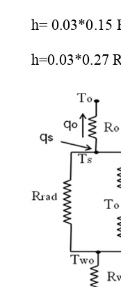
Figure 4 shows the thermal resistance diagram for the roof side with a shade wall.
2.2 Convective heat transfer correlations
Outside convective heat transfer depends on the wind velocity. The effect of buoyancy (natural convection) usually negligible compared with forced convection. The most used correlation in estimated convective heat transfer coefficient in calculating the thermal resistance is the correlation suggested by Jurges [11],
ho = 4.0 U+5.6 for U< 5 m/s (15a) ho =7.1 U0.78 for U > 5 m/s (15b)
Wall
q
iq
sq
sh,oT
iT
oT
oq
radwhere U is the wind velocity.
Computational fluid dynamics analyzes of Defraega et al. [12] suggest the following correlations, ho =5.01 U0.85 for windward (16a) ho =2.27 U0.83 for leeward (16b) Equations (16) underestimated the value of convective heat transfer compared with values predicted by equation (15). For instance, for wind velocity of 5.0 m/s (18 km/hr) heat transfer coefficient estimated by equations (15) and equations (16) are 24.9 and 19.7 W/m2K, respectively.
Heat transfer between inner wall and air in the room is dominated by natural convection. Churchill and Chu [13] suggested the following formula for air (Pr=0.71),
hi = 0.03 [0.825 + 0.324 Ra1/6]2/H (17) where Ra and H are Rayleigh number and height of the wall, respectively.
For Ra=1011 and H=2.5 m, hi = 6.1 W/m2K.
For the case of unshaded roof, the following correlation can be used [13]:
h= 0.03*0.15 Ra1/3/L (18a) for shaded roof
h=0.03*0.27 Ra1/4/L (18b)
where L is the roof width.
Fig. 4. Thermal resistance diagram for the roof with a shading
For typical value of summer outdoor temperature of 40 oC, indoor conditioned temperature of 22 oC, ho= 15 W/m2K, hi= 10 W/m2K, calculations performed for a range of solar flux are displayed in Fig. 5 and Fig. 6 for Rw =0.1m2K/W (light wall) and Rw =0.4 m2K/W (relatively thick wall), respectively. It is very clear that shading has significant effect on the exterior wall temperature for both light and thick walls. The exterior wall temperature is within the range of ambient temperature for shaded wall. However, for non-shaded wall the exterior wall temperature is drastically higher than the ambient temperature and can reach about 90 oC.
Adding ventilated shadings to the walls reduces the rate of heat transfer. Adding a thin shading to a vertical wall creates natural convection flow, where the air channels through the gap.
Fig. 5. Variation of the temperature with the solar flux for the cases with and without shading and for light walls (Rw=0.1 m2K/W)
Fig. 6. Variation of the temperature with the solar flux for the cases with and without shading and for thick walls (Rw=0.4 m2K/W)
Fig. 7.Distribution of the heat flux transferred in the room through the wall for the cases with and without shade for light wall (Rw=0.1 m2K/W)
Solar Flux (W/m2)
Te m pe rat ur e (C )
200 400 600 800 1000
40 50 60 70 80 90
Wall temp. without shading Shade temp
Wall temp. with shading
Solar Flux (W/m2)
Te m pe rat ur e (C )
200 400 600 800 1000
40 50 60 70 80 90
Wall temp. without shading Shade temp Wall temp. with shading
Solar Flux (W/m2)
F lu x-i n (W /m2 ) %
200 400 600 800 1000 50 100 150 200 250 300 350 0 20 40 60 80 100
Fig. 8. Distribution of the heat flux transferred in the room through the wall for the cases with and without shade for thick wall (Rw=0.4 m2K/W)
2.3 Natural convection between a wall and shading
Finite volume method is used to simulate fluid flow and heat transfer through the wall without and with shading. The main objective of using CFD is to understand the flow pattern and temperature field due to added shading. The code was tested before for many natural convection problems. Hence, there is no need to repeat the details of the methodology of solution (interested readers can find the details in [6,7]). However, it is worthy to mention that it is found that grids of 150x150 is sufficient enough to produce numerically accurate results. Also, it is assumed that the pressure is constant at the open boundaries. If the flow toward the domain the outdoor temperature is imposed at the boundary; if the flow leaving the domain the temperature at the boundary is set to the temperature of the adjustment node to the boundary [8].
Figures 9 and 10 give some results obtained using the numerical model. These results are expressed in terms of streamlines and isotherms for the case of walls with shading.
3 Conclusion
The present study analyses using artificial naturally ventilated shading covers to reduce the effect of solar energy. The results are obtained using a first order approach based on the thermal resistance model and a CFD model. Accurate and appropriate correlations for the heat transfer coefficients are used in the first model. It is shown that the surface wall temperature is reduced significantly when a shading is used. The heat flux transferred through the wall into the room is also decreased.
Further results are under analysis and will be published soon.
Acknowledgement
This project is funded by the Sustainable Energy Technologies Program, King Saud University. Solar Flux (W/m2)
F
lu
x-i
n
(W
/m2
)
%
200 400 600 800 1000
20 40 60 80 100 120 140 160
0 5 10 15 20 25 30 35 40 45 50
Fig. 9. Streamlines distribution for the case of shaded wall.
Fig. 10.: Isotherms distribution for the case of shaded wall. X
Y
0 0.2 0.4 0.6 0.8 1
0 0.2 0.4 0.6 0.8 1
0.1
0
.1
0.1
0.
4
0.4
0 .4
0.7
0.7
1
1
1
1
1
1
1 .4
X
Y
0 0.2 0.4 0.6 0.8 1
References
1. M. Santamouris and D. Assimakopoulos (Eds), Passive Cooling of Buildings, James and James Science Publishers, London, UK, (1996)
2. B. Givoni, Passive and Low Energy Cooling of Building, John Wiley and Sons, Inc., USA, (1994)
3. M. Santamouris, Passive Cooling of Buildings, Advances of Solar Energy, ISES, James and James Science Publishers, London, UK, (2005).
4. A. Tzempelikos and A. K. Athienitis, The impact of shading design and control onbuilding and lighting demand, Solar Energy 81 369 (2007)
5. N.M. Nahar, P. Sharma, and M.M. Purohit, Performance of different passive techniques for cooling of buildings in arid regions, Building and Environment, 38 109 (2003)
6. Jorge L. Alvarado and Edgard Martinez, Passive cooling of cement-based roofs in tropical climates, Energy and Buildings 40 358 (2008)
7. J.T. Oliveira, Aya Hagishima and Jun Tanimoto, Estimation of passive cooling efficiency for environmental design in Brazil, Energy and Buildings 41 809 (2009)
8. M. Muselli, Passive cooling for air-conditioning energy savings with new radiative low-cost coatings, Energy and Buildings 42 945 (2010)
9. S. J. Kumar, G. N. Tiwari and N. C. Bhagat, Amalgamation of Traditional and Modern Cooling Techniques in a Passive Solar House: A Design Analysis, Energy Convers. Mgmt
35 671 (1994)
10. T. G. Theodosiou, Summer period analysis of the performance of a planted roof as a passive cooling technique, Energy and Buildings, 35 909 (2003)
11. W. Jürges, The heat transfer at a flat wall (Der Wärmeübergang an einer ebenenWand), Beiheftezum Gesundh.-Ing. 1 19 (1924)
12. T. Defraeya, B. Blocken and J. Carmeliet, Convective heat transfer coefficients for exterior building surfaces: existing correlations and CFD modeling, Energy Conversion and Management Energy Conversion and Management, 52 512 (2011
13. S. W. Churchill and H. H. S. Chu, Int. J. Heat and Mass Transfer, 18, 1323 (1975)
14. A.A.Mohamad, J. Sicard, R. Bennacer, Natural convection in enclosures with floor cooling subjected to a heated vertical wall, International Journal of Heat and Mass Transfer,
49 108 (2006)
15. H. K. Versteeg and W. Malalasekera, An Introduction to Computational FluidDynamics: The
Finite Volume Method, Pearson and Prentice Hall, 2nd edition, (2007)