Performance of Pre-Stressed Sandwich Composites
Subjected to Shock Wave Loading
E. Wang, and A. Shuklaa
Dynamic Photomechanics Laboratory, Dept. of Mechanical, Industrial and Systems Engineering University of Rhode Island, 92 Upper College Rd, Kingston, RI, 02881, USA
Abstract. The present paper experimentally studies the dynamic behaviour of pre-stressed sandwich composites under blast loading. The in-plane static compression loadings are implemented on the sandwich composites before they are subjected to the transverse shock wave loading. Three different pre-stress levels are chosen. 3-D real-time deformation data are captured by two high-speed photography systems: a back-view Digital Image Correlation (DIC) system and a side-back-view camera system. The results show that pre-stresses can induce local buckling in the front face-sheet of sandwich composites, consequently reduce the blast resistance of sandwich composites.
1 Introduction
Ship hull structures always undergo longitudinal compressive loading and their longitudinal strength is the most fundamental and important strength to ensure the safety of a ship structure [1]. When these pre-stressed structures are subjected to transverse blast loading, the coupling of the in-plane pre-load and transverse blast loading will likely reduce the blast resistance of marine structures.
The dynamic responses of in-plane pre-stressed composite structures under low-velocity transverse impact have been studied. Heimbs et al.[2] tested carbon-fibre/epoxy laminated plates under an in-plane compressive pre-load. An increased deflection and energy absorption was observed under a pre-load of 80% of the buckling load. Sun et al. [3] and Choi [4] analytically investigated the effects of pre-stress on the dynamic response of composite laminates. They found that the initial in-plane tensile load increased the peak contact force while reducing the total contact duration and deflection. The compressive load reacted oppositely. However, the most recent research on composite structures focuses only on the blast resistance without any in-plane pre-load. There are very few theoretical and numerical studies [5] related to the blast response of pre-stressed structures. To date no experimental investigations on pre-stressed structures under blast load have been done.
The present paper experimentally studies the dynamic behaviour of pre-stressed sandwich composites under blast loading. A special fixture is designed in order to enable different in-plane static compression loading on the sandwich composites before they are subjected to the same level transverse shock wave loading. Three different pre-stress levels are chosen to study the effect of the pre-stress on the dynamic response of the sandwich composites. A back-view Digital Image Correlation (DIC) system and a side-view camera system are utilized to capture 3-D real-time
ae-mail : [email protected]
© Owned by the authors, published by EDP Sciences, 2010 DOI:10.1051/epjconf/20100624006
deformation of the specimen. These results are used to analyze the mechanism of dynamic failure of the pre-stressed sandwich composites.
2 Materials and specimens
The skin materials that were utilized in this study are E-Glass Vinyl Ester (EVE) composites. The woven roving E-glass fibres of the skin material were placed in a quasi-isotropic layout [0/45/90/-45]s. The fibres were made of the 18 oz/yd2 area density plain weave. The resin system used was
Ashland Derakane Momentum 8084 and the front skin and the back skin consisted of identical layup and materials. The core material used in the present study was CorecellTM P600 styrene foams,
which is manufactured by Gurit SP Technologies specifically for blast defence applications. Table 1 lists important material properties of this foam from the manufacturer’s data [6].
Table 1. Material properties of foam core [6].
Nominal Density
(kg/m3)
Compression Modulus
(MPa)
Compression Strength
(MPa)
Shear Elongation
%
CoreCell P600
122 125 1.81 67%
The VARTM procedure was carried out to fabricate sandwich composite panels. The overall dimensions for the specimen were 102 mm wide, 254 mm long and 33 mm thick. The foam core itself was 25.4 mm thick, while the skin thickness was 3.8 mm. The average areal density of the samples was 17.15 kg/m2. Fig. 1 shows a real image of a specimen and its dimensions.
Fig. 1. The sandwich specimen and over all dimensions.
3 Experimental setup and procedure
3.1 Shock tube
The shock tube apparatus was utilized in present study to obtain the controlled blast loading. The detail of this apparatus can be found in Ref.[7]. Fig. 2 shows the shock tube apparatus with muzzle detail. The final muzzle diameter is 76.2 mm. Two pressure transducers (PCB102A) are mounted at the end of the muzzle section with a distance 160 mm. The support fixtures ensure simply supported boundary conditions with a 152.4 mm span.
254 mm 33 mm
Fig. 2. Shock tube apparatus.
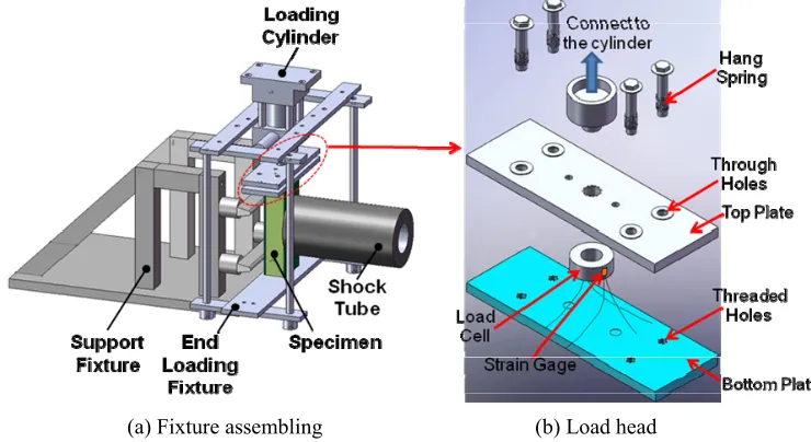
3.2 Pre-loading fixture
Fig. 3 shows the fixture used to apply the in-plane static compression loading on the sandwich composite panels. The loading head is connected to a hydraulic loading cylinder, which is mounted on the frame. An aluminium cylinder with an outer-diameter Ø50.8 mm and an inner-diameter Ø38.1 mm is positioned between two plates. Two strain gages, which are attached on this aluminium cylinder, measure the deformation of this cylinder and then calculates the load applied on the specimen. The support fixture and in-plane pre-loading fixture are all securely fastened inside a dump tank.
Fig. 3. Pre-loading fixture.
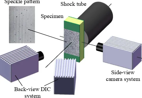
3.3 High-speed photography systems
Two high-speed photography systems were utilized to capture the real-time 3-D deformation data of the specimen. Fig. 4 shows the experimental setup. It consisted of a back-view 3-D Digital Image Correlation (DIC) system and a side-view camera system. All cameras used in the systems are Photron SA1 high-speed digital cameras. They have an ability to capture images at a frame-rate of
(a) Fixture assembling (b) Load head
20,000 fps with an image resolution of 512×512 pixels for a 1 second time duration. These cameras were synchronized to make sure that the images and data can be correlated and compared.
The 3-D DIC technique is one of the most recent non-contact methods for analyzing full-field shape, motion and deformation. The working mechanism of this technique is similar to how our eyes function. Two cameras capture two images from different angles at the same time. By correlating these two images, one can obtain the three dimensional shape of the surface. Correlating this deformed shape to a reference (zero-load) shape gives full-field in-plane and out-of-plane deformations. To ensure good image quality, a speckle pattern with good contrast was put on the specimen prior to experiments.
Fig. 4. High-speed photography system.
3.4 Experimental procedure
In the present study, the shock wave loading, generated by the shock tube, has an incident peak pressure of approximately 1 MPa and a wave velocity of approximately 1030 m/s. The in-plane compression loading was applied on the specimen and held at a constant level until the specimen is subjected to the transverse shock wave loading. Three levels of static compression loading were chosen: 0 kN, 15 kN, 25kN. For each compression loading, at least two samples were tested. When the shock wave was released, the computer and high-speed photography system were triggered to record the pressure data and deformation images.
4 Experimental results and discussion
4.1 Real time deformation data from high-speed photography system
Fig. 5 shows the real time deformation images of sandwich composites with different levels of compression pre-loading. The shock wave propagates from the right side of the image to the left side. Some deformation details are pointed out in the images.
From the images, it can be clearly seen that for the sandwich composite without pre-loading (0 kN), the front face-sheet shows a profile with a smooth and symmetrical curvature. This means there is no local buckling in the front face. For the sandwich composite with 15 kN pre-loading, the section of the front face-sheet, close to the lower support, exhibits more curvature than the section close to the upper support. This asymmetrical phenomenon means that there is a local buckling at the low section of the front face-sheet. At approx 1600 µs, the fibers debonding of the front face-sheet shows clearly that local buckling is evident. For the sandwich composite with 25 kN pre-loading,
Shock tube
Specimen
Back-view DIC system
there are two obvious kinks in the front face-sheet. This means that the local buckling happened in two positions of the front face-sheet.
Fig. 5. Real time deformation of sandwich composites with different pre-loading.
Fig. 6 shows the back face deflection contours of sandwich composites with different levels of compression pre-loading from DIC technique. It can be seen that the deflections of the panels with 0 and 15kN pre-loading are very similar. The panel with 25 kN pre-loading has higher deflection.
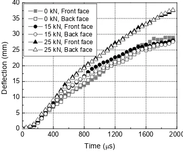
4.2 Deflections and in-plane strains
Fig. 7 shows the deflections of the middle point located on the front and back faces from the side-view high-speed images. From the plots, the defections of the front and back faces for each panel are almost overlapped. This means that there is no core compression in the core thickness direction. The panels with 0 and 15kN pre-loading have similar deflections while the deflection of the panel with 25 kN pre-loading is higher. Fig. 8 shows the in-plane strain eyy of the middle point of the back face
from the DIC technique. Here, the vertical direction is y axis. Though the deflections are almost identical, the back-face in-plane strain of the panel with 15 kN pre-loading is much higher than that with 0 kN pre-loading. This shows that the in-plane pre-loading reduces the blast resistance of the sandwich composites.
0 µs 400 µs 800 µs 1200 µs 1600 µs
0 kN
15
k
N
25
k
N
Local buckling Core
EPJ Web of Conferences
Fig. 6. Real-time full-field back-face deflection contour of sandwich composites with different pre-loading.
Fig. 7. Deflection of middle point at back and front faces.
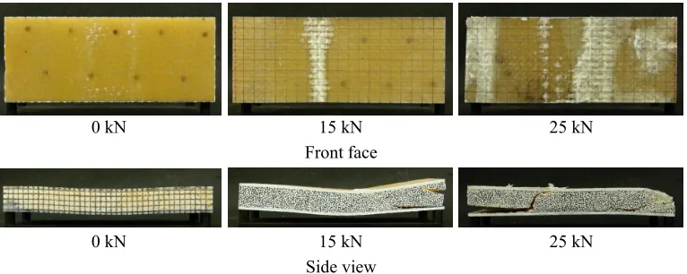
4.3 Post mortem analysis
The damage patterns of the sandwich panels after the shock event occurred were visually examined and recorded using a high resolution digital camera and are shown in Fig.9. Since the back faces don’t show any change after the experiments, only the front face and side view images are shown here. From the front face-sheet images, the local buckling positions show a clear trend. Note the
0 µs 800 µs 1600 µs
0 kN
15
k
N
25
k
N
0 400 800 1200 1600 2000
0 5 10 15 20 25 30 35 40
0 kN, Front face 0 kN, Back face 15 kN, Front face 15 kN, Back face 25 kN, Front face 25 kN, Back face
Deflection (mm)
yellow color is the original color of the specimen and the white color signifies fiber delamination and face-sheet buckling. For the panel with 0 kN pre-loading, there is no buckling on the front face. For the panel with 15 kN pre-loading, the buckling only occurred at one position. For the panel with 25 kN pre-loading, buckling occurred at two positions beside the center of the specimen. Those white areas at the end of the specimen are not due to local buckling induced by the pre-loading. It is due to the collision between the specimen and shock tube during the blast loading process. From the side view images, the core crack and delamination between the core and face sheets also increase with the increase of the in-plane pre-loading.
Fig. 8. In-plane strain on the back face.
Fig. 9. Post mortem images of sandwich composites
5 Summary and conclusion
Sandwich composites, with E-glass Vinyl Ester composite face sheet and CoreCellTM P600 foam
core, were in-plane pre-stressed prior to being subjected to a transverse shock wave loading. Three levels of pre-loading were chosen to study the effect of pre-stresses on the dynamic behavior of the sandwich composites. The results show that the pre-stresses induced the local buckling in the front face during the blast loading process. It weakened the sandwich composites, increased the back face deflection and in-plane strain of the back face-sheet and consequently reduced the blast resistance of the sandwich composites.
0 400 800 1200 1600 2000
0.000 0.004 0.008 0.012 0.016 0.020 0.024
eyy
Time (μs)
0 kN 15 kN 25 kN
x y
o
0 kN 15 kN 25 kN
Front face
0 kN 15 kN 25 kN
EPJ Web of Conferences
Acknowledgement
The authors kindly acknowledge the financial support provided by Dr. Yapa D. S. Rajapakse, under Office of Naval Research (ONR) Grant No. N00014-04-1-0268 and the support provided by the Department of Homeland Security (DHS) under Cooperative Agreement No. 2008-ST-061-ED0002. Authors also thank Dr. Stephen Nolet and TPI Composites for providing the facility for fabricating the materials used in this study.
References
1. T. Yao. Marine Structures, 16,1-13 (2003)
2. S. Heimbs, S. Heller, P. Middendorf, F. Hahnel, J. Weiße, International Journal of Impact Engineering, 36, 1182-1193 (2009)
3. C.T. Sun, J.K. Chen. Journal of Composite Materials, 19, 490-504, (1985) 4. I.H. Choi. Composite Structures, 86, 251-257 (2008)
5. F. Chen, T. Yu. Advances in Engineering Plasticity, 177, 255-260 (2000) 6. http://www.gurit.com
![Table 1. Material properties of foam core [6].](https://thumb-us.123doks.com/thumbv2/123dok_us/8101122.1351600/2.482.126.367.353.487/table-material-properties-foam-core.webp)