R E S E A R C H
Open Access
Robust depth enhancement and
optimization based on advanced
multilateral filters
Ting-An Chang, Yang-Ting Chou and Jar-Ferr Yang
*Abstract
Stereo matching of two distanced cameras and structured-light RGB-D cameras are the two common ways to capture the depth map, which conveys the per-pixel depth information of the image. However, the results with mismatched and occluded pixels would not provide accurately well-matched depth and image information. The mismatched depth-image relations would degrade the performances of view syntheses seriously in modern-day three-dimension video applications. Therefore, how to effectively utilize the image and depth to enhance themselves becomes more and more important. In this paper, we propose an advanced multilateral filter (AMF), which refers spatial, range, depth, and credibility information to achieve their enhancements. The AMF enhancements could sharpen the image, suppress noisy depth, filling depth holes, and sharpen the depth edges simultaneously. Experimental results demonstrate that the proposed method provides a superior performance, especially around the object boundary.
Keywords:Depth enhancement, Multilateral filter, Hole filling, Mold matching, Depth refinement
1 Introduction
In general, the three-dimensional (3D) video is widely recognized as a visual media technique which enables viewers to perceive the depth in a scene without special glasses. Owing to understanding the 3D video among users who wish to experiment extended visual sensa-tions, developments in 3D video technologies have initi-ated the commercialization of 3D services in consumer products such as 3D TVs [1], tablet PCs, mobile devices, and computer gaming devices. At the same time, the multi-view video plus depth (MVD) format has appeared as a potent technique for 3D video applications [2, 3]. To produce virtual views at desired viewpoints with low processing costs, the MVD format uses the depth-image-based rendering (DIBR) techniques [4–6]. The DIBR technique synthesizes images at the desired view-point by using the color image and its corresponding depth map. Thus, it can be treated as an efficient data format for the 3D video. Moreover, the depth map is an
image which represents the range information of the captured scene. The depth map is important because it affects the quality of the synthesized images.
The acquisitions of depth information can be catego-rized into two approaches: the indirect estimation ap-proach based on stereo matching of two images taken in different locations and the direct measure approach based on the time-of-flight of depth sensors. The stereo matching with visual computation estimates the depth map from two-view images [7–9]. However, its computa-tional complexity is high and its estimation accuracy would be fail in texture-less and occluded regions. Re-cently, the low-cost structured-light RGB-D cameras have been used to capture high-resolution color images and low-resolution depth maps [10]. Thus, depth map upsampling [11, 12] followed by its enhancement [13] becomes an inevitable task because the quality of the DIBR process heavily depends on the accuracy of depth information. To improve the depth map of RGB-D cam-eras, the following problems should be solved. First, the boundary of an object in the depth map would not be well matched with that of its corresponding color image. The region near the object boundary is commonly * Correspondence:[email protected]
Department of Electrical Engineering, Institute of Computer and Communication Engineering, National Cheng Kung University, Tainan, Taiwan
referred to the mismatched region. Secondly, the holes with no depth information often happened in the depth map because the infrared (IR) light can be absorbed or obstructed by the object. Thirdly, the depth map suffers from the optical noise because of multiple reflections or scatters of the IR light.
In general, the images usually have better quality but could not be well matched with the depth map. Thus, it is reasonable to assume that the depth maps usually have much worse quality with noisy, mismatched, and hole pixels. To overcome these problems, the joint bilat-eral filters (JBF) proposed [14–16] use color and spatial similarity between corresponding pixels in the image to enhance the depth map. Then, the iterative joint multi-lateral filtering (IJMF) suggested in [17] achieves the best unsharp masking structure through the training of pa-rameters. This iterative method not only enhances the sharpness of the image but also smooths the corre-sponding video pixel values; however, it requires a com-plex training process to obtain the parameters. In order to overcome the drawbacks of the IJMF method, the adaptive joint trilateral filter (AJTF) method has been proposed in [18] by using different designed patterns to test the differences between the image and its corre-sponding depth map. The depth map is then sharpened along object boundary borders and suitable for practical DIBR process [19–21]. However, this method is easy to be affected by complex image texture, which suffers ser-ious blocking effect in depth map for high texture objects.
In summary, the above methods cannot accurately en-hance the noisy depth maps with unmatched color image and depth map to result in distortion of the syn-thesized 3D image. Therefore, in this paper, we propose an adaptive multilateral filter (AMF) for effective depth enhancement. The AMF approach considers the similar-ities of the spatial, range, depth, and credibility informa-tion can successfully suppress the noise, filling the holes, and sharpening the object edges simultaneously. The rest of this paper is present as follows. In Section 2 the background and motivations are explained. In Section 3, the proposed advanced multilateral filter is addressed in details. The comparisons of subjective SSIM and PSNR performances and the viewing quality are exhibited in Section 4. Finally, conclusions of this paper are exhibited in Section 5.
2 Background and motivations
Generally, the source depth map could be generated by fast stereo matching technique with subsample stereo images or captured by RGB-D cameras with a lower resolution than the color image. Thus, the source depth map produced by fast stereo matching and depth camera usually has a lower resolution than the corresponding
color image and contains a lot of noisy pixels including unknown pixels due to occlusions. Thus, the source depth map will be first up sampled before depth en-hancement. In the paper, the traditional bicubic interpolation [22] is applied to recover the resolution of the source depth map to that of the corresponding color image. After upsampling depth map, we assume that the original texture and corresponding depth map, which are respectively expressed byg(x,y) andd(x,y), are with the same spatial resolution and come with some un-desired noisy pixels in depth maps and images. Specially, the foreground boundaries do not well match the corre-sponding color image and jagged boundaries are pro-duced from the interpolated depth map after the bicubic interpolation. If the depth is estimated by stereo match-ing algorithms, there exist mismatched and occluded pixels due to singularity properties. On the other hand, we cannot generate virtual image precisely by depth image-based rendering (DIBR), if the image and its cor-responding depth map cannot be matched successfully due to the noises and holes existed in depth maps. Hence, the enhancements of the image and its depth be-come very important in 3D visualization.
Thus, the upsampled depth map d(x,y) would be af-fected by three major factors with noisy, blurring, and missing pixels [23], where the noise pixels are caused by the distortion of capture devices resulting in unmatched depth, the blurring pixels are produced by interpolation filters mostly along object boundaries, and the missing pixels are mainly originated from the presence of object occlusions and concave objects. Thus, the quality im-provement of the upsampled depth mapd(x,y) becomes an important task in 3D visualization applications. In [23], the traditionally enhanced processing generally contains two stages including the suppressing noise and the image-depth enhancement. However, these stages take a high computational complexity and large compu-tational time.
the image and the corresponding depth map are smoothed to reduce the noisy and blurring pixels first. Then, the smooth enhancement can degrade the high-frequency noise. Then, the holes are crammed by sur-rounding neighbors. Finally, after AMF, the rolling guid-ance refinement (RCR) method is used to sharpen the object edges.
3 Proposed AMF algorithm 3.1 Advanced multilateral filter
As shown in Fig. 1, the proposed depth enhancement system is composed of two major steps, the advanced Image and
Corresponding Depth Map
Mold Matching
Distortion Calculation
Adjustment Parameters
Small structure Smoothing Edge
Rehabilitation
Enhanced Depth
Map
Execute Next Iteration? Final
Depth Map
Yes
No
Advanced multilateral Filter (AMF)
Rolling Guidance Refinement (RGR)
Fig. 1System block diagram for the advanced multilateral filter (AMF) and the rotating counsel filter (RCR)
multilateral filter (AMF) and the rotating counsel filter (RCR). We assume thatg(x,y) andd(x,y) with the same spatial resolution represent the original image and the corresponding depth map, respectively. The depth map, which could be captured and upsampled from a stereo camera or estimated by a stereo matching method, often comes with noise and holes. The proposed AMF en-hanced resultsg’(x,y) and d’(x,y) are respectively given as
g′ðx;yÞ ¼X
i;j∈Ω
h xð ;y;i;jÞg ið Þ;j ð1Þ
and
d′ðx;yÞ ¼X
i;j∈Ω
h xð ;y;i;jÞd ið Þ;j ð2Þ
Enhanced Depth Map
Small Structure Smoothing
Edge Rehabilitation
Final Depth Map
t
Threshold
+
Yes
No
Fig. 3Flow chart of rotating counsel refinement
(a) (b)
(c) (d)
(e) (f)
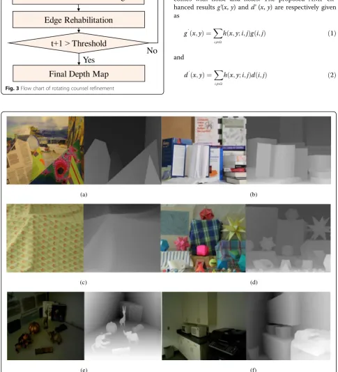
Fig. 4Four test images (left) and their corresponding depth maps (right):aArts(432 × 381),bBooks(463 × 370),cDoily(417 × 370),dMoebius
where the responseh(x,y;i,j) at the position (x,y) with respect to the impulse at (i,j), is defined by,
h xð ;y;i;jÞ ¼
JsJdJgJc
qx;y : ifð Þi;j ∈Ω
0; otherwise: 8
<
: ð3Þ
In (3), h(x, y; i, j) is the adaptive multilateral filter, which is used to enhance the noisy depth map,Ωis a se-lected filtering window, (x, y) is the coordinate of the center position of the window, and (i,j) are the neighbor positions of (x,y).Js,Jd,Jg, andJc are referred to spatial,
depth, range, and credibility filtering coefficients, which are respectively defined as
Js¼ exp −
x−i
ð Þ2þðy−jÞ2 2σs2
!
ð4Þ
Jd¼ exp −
d ið Þ;j−d xð ;yÞ
ð Þ2
2σd2
!
ð5Þ
Jg ¼ exp −
g ið Þ;j −g xð ;yÞ
ð Þ2
2σg2
!
ð6Þ
Jc¼1−exp −
c ið Þ ;j d ið Þ;j
2σc2
ð7Þ
where Js is the weight of the depth distance between center position and its corresponding neighbor position,
Jd is the weight of the depth difference between center position and its corresponding neighbor position, Jg is the weight of the texture difference between center pos-ition and its corresponding neighbor pospos-ition, Jc is the weight of the enhancement of the depth map, which is near the texture image edge. In (3), the normalization factor is given as
qx;y¼X
i;j∈ΩJsJdJgJc: ð8Þ
In (7), the credibility map, c(x,y) is computed from texture image as
c xð ;yÞ ¼ 1; G xð ;yÞ≥ϕ
0; G xð ;yÞ<ϕ
ð9Þ
(a)
(b)
(c) (d)
whereϕis a selected threshold andG(x,y) is the magni-tude of gradient of texture image as
G xð ;yÞ ¼
ffiffiffiffiffiffiffiffiffiffiffiffiffiffiffiffiffiffiffiffiffiffiffiffiffiffiffiffiffiffiffiffiffiffiffiffiffiffiffiffiffi
Gx2ðx;yÞ þGy2ðx;yÞ
q
: ð10Þ In (10), the horizontal and vertical direction gradients, Gx(x,y) andGy(x,y) are computed from Sobel operators
[24]. According to (9), the credibility map can be determined if the pixel is in smooth or edge region. If the corresponding candidate ofd(i,j) is in edge regions, c(i,j) = 1. The corresponding candidate depth, d(i,j) will be strengthened with the weight controlled by (7). The AMF will be given a strong weight by Jc to enhance d(x,y). On the other hand, if the corresponding can-didate of d(i,j) is in smoothing regions, c(i,j) = 0 such that the corresponding candidate depth, d(i,j) is weakened with the weight controlled by (7).
To reduce computation in exponential functions, Taylor expansion formula is used to approximate the ex-ponential function as
ew≈p wð Þ ¼1þwþw
2
2 : ð11Þ
With (3) and (11), the approximated AMF impulse re-sponse then becomes
where the spatial, depth, range, and credibility filtering coefficients respectively become
It is noted that we need to determine four standard deviations,σs,σd,σg, andσcto achieve the best enhance-ment of depth map, where the mold matching technique is used for the selection of AMF parameters.
3.2 Mold matching for image and depth map
The mold is used to match image and corresponding depth map. In this paper, as shown in Fig. 2, there are 56 binary molds,Mm, form= 1, 2,…, 56 for mold
classi-fication of image and depth blocks. The designed 11 × 11 molds could cover all possible edges and corners of the blocks of image and depth map.
Table 1PSNR comparisons with different approaches on Middlebury dataset and RGBD dataset
Methods\image data Art Books Doily Moebius RGBD_1 RGBD_2
JBF [16] with CHF 32.4373 33.3130 34.6370 33.5519 26.3400 31.1924
IGDS [39] with CHF 37.9567 41.2789 43.3450 41.4567 30.3135 32.8103
CSDU [40] with CHF 37.6181 40.6110 41.3045 42.0501 30.3520 33.6959
AJTF [18] with CHF 32.4128 29.2324 29.5552 29.3657 27.6347 31.4258
Proposed method 39.0004 41.3019 41.7411 42.5622 31.6245 33.7466
(a) (b) (c) (d)
Let Mm represent the mth mold and Ig be the best
mold index when a′n be the smallest anfor the 11 × 11
block ofg. The computation for finding the best match-ing mold can be expressed as
a′n¼ minf gan ; n¼1;2;…;NR ð18Þ
In (18), an denotes the matching error between the nth mold and the image block. Thus, the minimum of anrepresents the best matching mold to the image block
among all the candidate molds. NR, which is 56, is the
number of total molds, R0
n and R1nrespectively represent the black and white regions in thenth mold as shown in Fig. 2. Withk= 0 or 1,ηk
j is the average of texture values inRk
n, and Rkn denotes the number of elements inRkn. In (19), we use the least squares error method to predict the best mold,MIg for the image block. To find the best
Art Books
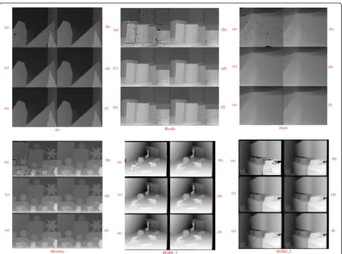
Fig. 7Results of the depth enhancement coupled with hole filling results obtained byanoisy depth map,bjoint bilateral filter (JBF) [16], cintensity guided depth superresolution (IGDS) [39],dcompressive sensing based depth upsampling (CSDU) [40],eadaptive joint trilateral filter (AJTF) [18], andfthe proposed AMF forArt,Books,Doily,Moebius,RGBD_1, andRGBD_2
Table 2PSNR comparisons with sensitive of parameters on
Middlebury and RGBD dataset
Image data σs=2,k1=15,
k2= 15,k3= 18
σs=2,k1=10,
k2= 10,k3= 12
Virtual depth maps Art 39.0004 38.8735
Moebius 42.5622 41.6602
Natural depth maps RGBD_1 31.6245 31.1052
mold for the depth block, MId, we can simply replace g(xm) with d(xm) in (19) and (20). In addition, if the
block variance is less than a given threshold, e.g., 1, we would assume that the corresponding block belongs to the smooth region. In this case, a new binary mold can be assigned by consisting of all elements with 1’s or 0’s, denoted byM0.
By comparing similarity of the best molds of depth map and image blocks, the sum of absolute differences (SAD) is used to calculate the discrepancy, and the local similarity is measured by the mold matching distortion, Dpm, as:
Dpm¼
min SAD MId;MIg
;SAD MId;MIg
Dmax
ð21Þ
where
SAD að ;bÞ ¼X
m∈Bja mð Þ−b mð Þj: ð22Þ
The SADs between two binary molds represents the total number of mismatched pixels. The SADs of the
(a) (b)
(c) (d)
(e) (f)
Fig. 8Four depth map results obtained by the AMF (left side) and by the AMF and the RGR (right side):aArt,bBooks,cDoily,dMoebius, eRGBD_1, andfRGBD_2
(a)
(b)
Fig. 9Two selected regions obtained by the AMF (left side) and by the AMF coupled with the RGR (right side):aArtandbDoily
Table 3PSNR performances achieved by AMF and RCR
methods on Middlebury dataset and RGBD dataset
Image data Art Books Doily Moebius RGBD_1 RGBD_1
mold and its binary inversion of the depth map compar-ing to the image mold, which are denoted {MId;MIg}
and {MId;MIg}, are respectively computed. Then, the
minimum SAD is used to represent the mold similarity. It is worth noting that SAD MId;MIg
is necessary be-cause the binary mold only classifies the block pixels into two different groups. If we reverse bits in all molds, the mold matching processes defined in (18), (19), and (20) will achieve the same results. It means texture image and depth map corresponding to each binary mold with all the black region and white region swap, the similarity between the two molds will not be chan-ged. Since the smallest SADwill be generated by Dmax, Dmax denotes the largest SAD between any two molds,
the mold similarity after normalization of Dmax, the
value ofDpmis between 0 and 1. In Fig. 2, by comparing
them one-by-one, we found that the maximum SAD is Dmax= 83. The value of Dmax is defined as the largest
difference between the image mold and the depth mold. According to matching of depth map and image, we can useσg,σdandσcto adjust the influence of the range,
depth and credibility filters. Thus, three standard devia-tions according toDpmare given as:
σg ¼ max σg;L;min σg;U;k1⋅Dpm and upper limits, respectively. Thus, for the AMF, we can linearly increase or decreasek1, k2 and k3to adjust the strong or weak influence ofDpm.
3.3 Rotating counsel refinement for depth map
After the AMF enhancement, the tiny jagged edges will produce some errors in the synthesis view of the DIBR technology, for example, the boundary of the object is extended to the wrong region. Therefore, the RCR method [25] is used to adjust the object edge of the enhanced depth map. Thus, there exist several algo-rithms can effectively detect edges and eliminate jagged edges [26], such as guided filter [27, 28], geodesic filters [29, 30], weighted median filters [31, 32], and bilateral
filter [33–35]. In this paper, we suggest the rotating counsel refinement (RCR), the filtering, is used to re-move the tiny jagged edge of enhanced depth maps. The RCR process is implemented in an iterative manner [36], where the iterative RCR is composed of two major steps, including small structure smoothing and edge recovery as illustrated in Fig. 3. The RCR method uses the Gaussian filter to smooth the enhanced depth map, the enhanced depth map is called the guided depth map after the Gaussian filter, then the guided depth map is used to iterate the original enhanced depth map and sharpen the tiny jagged edges.
4 Experimental results
To evaluate the effectiveness of advanced multilateral fil-ter (AMF) and the rolling guidance refinement (RGR), the proposed depth enhancement system is experimen-ted on Middlebury database [37, 38] and RGBD data-base. Virtual depth maps are generated by the stereo matching method on the Middlebury database, in addition, natural depth maps are produced by the stereo camera on the RGBD database. Figure 4 shows six test images, Art, Books, Doily, Moebius, RGBD_1, and RGBD_2 used for evaluating the performance of depth enhancement and depth refinement.
4.1 Performance evaluation of depth enhancement In experiments, the weighted factors are empirically set as k1=15, k2= 15, k3= 18 in (23)–(25) and ϕ is set to
240 in (9). Decreases or increases of the above factors will result in strong or weak enhancement of the results. For comparisons of subjective performances, the pro-posed method without using any hole filling is compared to the joint bilateral filter (JBF) [16], intensity guided depth superresolution (IGDS) [39], compressive sensing based depth upsampling (CSDU) [40], and adaptive joint trilateral filter (AJTF) [18] methods all coupled with cross-based hole filling (CHF). After depth enhance-ment, the enhanced depth maps by the proposed AMF process as well as JBF and AJRF methods with CHF are
Table 4RMSE performances achieved by different depth enhancement methods on Middlebury dataset and RGBD dataset
Downsampled JBF [16] with CHF IGDS [39] with CHF CSDU [40] with CHF AJTF [18] with CHF AMF AMF with RCR
2× 2.89 1.56 1.72 2.42 1.15 1.08
4× 3.13 1.88 2.05 2.74 1.54 1.41
8× 4.26 2.67 3.22 3.51 2.73 3.06
Table 5Execution time of three main stages in the proposed
method
Stage AMF RCR
shown in Fig. 7. The simulation results show that the proposed AMF method effectively removes the noise and hole pixels, but the enhanced depth map still exists tiny jagged edges. Therefore, the depth refinement along object edges is another important step.
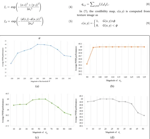
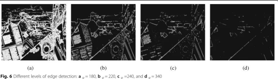
In Fig. 5a, if the value of the threshold ϕis too small, many unnecessary details of the texture will be pro-duced, if the value of the threshold ϕ is too large, the strong edge regions of the color image will be excluded; therefore, the performance of the AMF will be affected by the threshold ϕ. Different levels of edge detection simulation results are shown in Fig. 6.
Table 1 shows the PSNR performances between the ground truth and the depth enhancement results ob-tained by different methods. In Table 1, the maximum PSNR values achieved by the proposed method are 39.0004, 41.3019, 41.7411, 42.5622, 31.6245, and 33.7466 dB, respectively, while the minimum PSNR values achieved by AJTF [18] with CHF are 32.4128, 29.2324, 29.5552, 29.3657, 27.6347, and 31.4258 dB, re-spectively. We learn that the proposed method achieves the improvements with PSNR 6.5876, 12.0695, 12.1859, 13.1965, 3.9898, and 2.3208 dB. The PSNR subjective performances show that the proposed method performs better than the JBF [16] with CHF, IGDS [39] with CHF, CSDU [40] with CHF, and AJTF [18] with CHF. It is noted that the proposed method does not need the hole filling before the enhancement procedures. The best re-sult for each sample is highlighted through bold face type. Table 2 shows the PSNR comparisons with sensi-tivity of parameters on Middlebury and RGBD datasets. The strong depth enhancement has sharpening edges of
objects, but there will be accompanied by tiny jagged edges; on the other hand, the weak depth enhancement has smoothing edges of objects, but the PSNR value is worse than the strong depth enhancement relatively (Fig. 7).
4.2 Depth enhancement with RCR process
So as to assess the performance of the AMF for depth enhancement coupled with rotating counsel refinement, some parameter values based on experience need to be determined. In simulations, we also found that the rotat-ing counsel iterations converge speedily. Unlike trad-itional refinement methods, the procedure of the RCR converges to a significant depth map faithful to the input no matter how many iterations are performed. Figure 8 shows results for testing depth maps. Figure 9 shows the details of the results which are the magnified portions of Fig. 8a, c, when the AMF and the RGR (AMF_RGR) are both applied to refine the depth maps. Table 3 shows the PSNR results when AMF and RGR methods are both used. The depth maps after RCR process, in the object-ive of the simulation results, the PSNR values of refined depth maps are increased, in the subjective simulation results, the tiny jagged edge problems are also resolved. Table 4 shows that under the global error measurement, the proposed method is better than the JBF and AJTF methods, and more so when increasing the resolution of depth maps.
Table 5 exhibits the execution time of AMF and RCR stages suggested in the proposed depth enhancement system. Table 6 shows the total execution time required by different methods. The proposed method is much
Table 6Execution time of related methods and proposed method
Methods JBF [16] with CHF IGDS [39] with CHF CSDU [40] with CHF AJTF [18] with CHF Proposed method
Execution time (s) 86.0164 253.1741 191.5807 172.4393 184.9626
more effective than the JBF and AJTF, but the calcula-tion time is only 3.59% longer than the AJTF. So, it is worthwhile from the cost-effective ratio of viewpoint, where the experiments are carried on an Intel Core i7-4770 CPU computer with a 12-GB RAM and tested on the Matlab platform (Version R2013a).
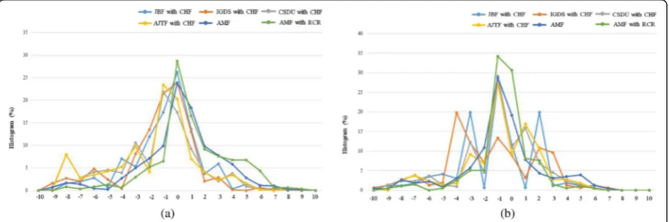
The histograms of horizontal depth value and vertical depth value are shown in Fig. 10. In order to obtain an objective evaluation of the enhanced depth map quality, the enhanced depth map quality metric suggested in [41] is used for comparisons. In Fig. 10a, the enhanced depth map of the proposed method has smaller depth values in the left half of histogram, representing less vis-ual fatigue; in Fig. 10b, the enhanced depth map of the proposed method focusses on the central region of the histogram which means less visual fatigue.
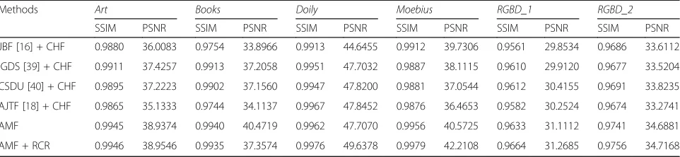
4.3 Performance evaluation with Middlebury datasets In order to understand the quality of the enhanced depth map, the depth image-based rendering proposed in [21] is used to produce the synthesized views from the depth maps obtained by different depth enhance-ment methods. For objective evaluations, the SSIM and PSNR performances are shown in Table 7. The best re-sult for each sample is highlighted through bold face type. The proposed approach gives better the SSIM and PSNR results than JBF [16] and AJTF [18].
5 Conclusions
The image and depth enhancements play an important role in nowadays 3D video technologies. Many ap-proaches are proposed to deal with different situations. We present a new robust adaptive method based on the adaptive joint trilateral filter (AJTF) to enhance the image and noisy depth maps. In this paper, we propose an advanced multilateral filter (AMF), which considers the similarities of the spatial, range, depth, and credibil-ity information. The AMF is used for the depth en-hancement by suppressing the noise, filling the holes and sharpening the object edges simultaneously. Finally, the proposed method performs the better results than the other method in the experiments.
The proposed AMF without hole filling outperforms the AJTF and the JBF with CHF. The proposed AMF produces sharper object edges and removes overshoot and undershoot artifacts. Besides, the proposed AMF method can remove hole regions and sharpen edges sim-ultaneously. The proposed method replaces the expo-nential function with the second order Taylor expansion function, which can save 12.69% of the computing time on MATLAB platform. We compare the proposed AMF method with different depth enhancement algorithms; the AMF exhibits better performance in subjective and objective identification.
As a future work, the research direction of the AMF with the hardware VLSI circuits should be considered. In conjunction with DIBR techniques, the edge detection should be more accurate in small object edges such that the DIBR technique requires extremely accurate depth maps. Finally, the proposed method can be extended to depth video enhancement by employing the temporal depth information between successive frames.
Funding
This work was supported in part by the National Science Council of Taiwan, under Grant NSC 105-2221-E-006-065-MY3.
Authors’contributions
TAC carried out the image processing studies, participated in the proposed system design, and drafted the manuscript. YTC carried out the mold design and adjustment parameters. JFY conceived of the study, and participated in its design and coordination and helped to draft the manuscript. All authors read and approved the final manuscript.
Competing interests
The authors declare that they have no competing interests.
Publisher’s Note
Springer Nature remains neutral with regard to jurisdictional claims in published maps and institutional affiliations.
Received: 12 December 2016 Accepted: 26 June 2017
References
1. L Zhang, C Vazquez, S Knorr, 3D-TV content creation: automatic 2D-to-3D video conversion. IEEE Trans. on Broadcasting57(2), 372–383 (2011) 2. A Smolic, D McCutchen, 3DAV exploration of video-based rendering
technology in MPEG. IEEE Trans. on Circuits Syst. Video Technology
14(3), 3448–356 (2004)
Table 7SSIM and PSNR performance achieved by different depth enhancement methods on Middlebury dataset and RGBD dataset
Methods Art Books Doily Moebius RGBD_1 RGBD_2
SSIM PSNR SSIM PSNR SSIM PSNR SSIM PSNR SSIM PSNR SSIM PSNR
JBF [16] + CHF 0.9880 36.0083 0.9754 33.8966 0.9913 44.6455 0.9912 39.7306 0.9561 29.8534 0.9686 33.6112
IGDS [39] + CHF 0.9911 37.4257 0.9913 37.2058 0.9951 47.7032 0.9887 38.1115 0.9610 29.9120 0.9677 33.5204
CSDU [40] + CHF 0.9895 37.2223 0.9902 37.1560 0.9947 47.8200 0.9881 37.0544 0.9612 30.4155 0.9691 33.8235
AJTF [18] + CHF 0.9865 35.1333 0.9744 34.1137 0.9967 47.8452 0.9876 36.4653 0.9582 30.2524 0.9674 33.2741
AMF 0.9945 38.9374 0.9940 40.4719 0.9962 47.7070 0.9956 40.5725 0.9633 31.1112 0.9741 34.6881
3. HM Wang, CH Huang, JF Yang,Depth maps interpolation from existing pairs of keyframes and depth maps for 3D video generation. IEEE Circuits and Systems(ISCAS)Conf, 2010, pp. 3248–3251
4. M Schmeing, X Jiang, Faithful disocclusion filling in depth image based rendering using superpixel-based inpainting. IEEE Trans. on Mutimedia
PP(99), 1 (2015)
5. F Shao, M Yu, G Jiang, F Li, Z Peng, Depth map compression and depth-aided view rendering for a three-dimensional video system. IET Trans. on Signal Process.6(3), 247–254 (2012)
6. TC Yang, PC Kuo, BD Liu, JF Yang, Depth image-based rendering with edge-oriented hole filling for multiview synthesis. Communications, circuits and systems (ICCCAS) Conf.1, 50–53 (2013)
7. YS Heo, KM Lee, SU Lee, Robust stereo matching using adaptive normalized cross-correlation. IEEE trans. on pattern analysis and machine intelligence
33(4), 807–822 (2011)
8. H Hirschmuller, D Scharstein,Evaluation of cost functions for stereo matching. IEEE Computer Vision and Pattern Recognition(CVPR)conf, 2007, pp. 1–8
9. D Scharstein, C Pal,Learning conditional random fields for stereo. IEEE Computer Vision and Pattern Recognition(CVPR)conf, 2007, pp. 1–8 10. F Garcia, D Aouada, T Solignac, B Mirbach, B Ottersten, Real-time depth
enhancement by fusion for RGB-D cameras. IET Computer Vision
7(5), 1–11 (2013)
11. J Xie, RS Feris, MT Sun, Edge-guided single depth image super resolution. IEEE Trans. on Image Process.25(1), 428–438 (2016)
12. MY Liu, O Tuzel, Y Taguchi,Joint geodesic upsampling of depth images. IEEE Conf. on Computer Vision and Pattern Recognition, 2013, pp. 169–176 13. J Yang, X Ye, K Li, C Hou, Y Wang, Color-guided depth recovery from RGB-D
data using an adaptive autoregressive model. IEEE Trans. on Image Process.
23(8), 3443–3458 (2014)
14. Y Shen, J Li, C Lu,Depth map enhancement method based on joint bilateral filter. IEEE Image and Signal Process. Conf, 2014, pp. 153–158
15. Y Wang, A Ortega, D Tian, A Vetro,A graph-based joint bilateral approach for depth enhancement. IEEE Speech and Signal Process. Conf, 2014, pp. 885–889
16. J Kopf, MF Cohen, D Lischinski, M Uyttendaele, joint bilateral upsampling. ACM Trans. on Graph26(3), p.96 (2007)
17. P Lai, D Tian, P Lopez,Depth map processing with iterative joint multilateral filtering. IEEE Picture Coding Symposium(PCS), 2010, pp. 9–12
18. SW Jung, Enhancement of image and depth map using adaptive joint trilateral filter. IEEE Trans. on Circuits and Syst. for Video Technology
23, 258–269 (2013)
19. H Shan, WD Chien, HM Wang, JF Yang,A homography-based inpainting algorithm for effective depth-image-based rendering”. IEEE Image Processing
(ICIP), 2014, pp. 5412–5416
20. CH Hsia, Improved depth image-based rendering using an adaptive compensation method on an autostereoscopic 3-D display for a Kinect sensor. IEEE Sensors Journal15(2), 994–1002 (2015)
21. P Ndjiki-Nya, M Koppel, D Doshkov, H Lakshman, P Merkle, K Muller, T Wiegand, Depth image-based rendering with advanced texture synthesis for 3-D video. IEEE Trans. on Multimedia13(3), 453–465 (2011) 22. H Chang, DY Yeung, Y Xiong, Super-resolution through neighbor
embedding. IEEE Computer Vision and Pattern Recognition1, I (2004) 23. NE Yang, YG Kim, RH Park,Depth hole filling using the depth distribution of
neighboring region of depth holes in the Kinect sensor. IEEE Signal Process., Communication and Computing Conf, 2012, pp. 658–661
24. ME Sobel, Asymptotic confidence intervals for indirect effects in structural equation models. Sociological methodology13, 290–312 (1982) 25. TA Chang, JF Yang,Enhancement of depth map using texture and depth
consistency. IEEE Conf.(TENCON), 2016, pp. 1139–1142
26. P Perona, J Malik, Scale-space and edge detection using anisotropic diffusion. IEEE Trans. Pattern Analysis and Machine Intelligence12(7), 629–639 (1990) 27. K He, J Sun, X Tang, Guided image filtering. IEEE Trans. Pattern Analysis and
Machine Intelligence35(6), 1397–1409 (2013)
28. CP Cuong, WJ Jae, Efficient image sharpening and denoising using adaptive guided image filtering. IET Image Process.9(1), 71–79 (2015)
29. A Criminisi, T Sharp, C Rother, P Perez, Geodesic image and video editing. ACM Trans. Graph29(5), 134 (2010)
30. Q Yang, D Li, LH Wang, M Zhang,A novel guided image filter using orthogonal geodesic distance weight. IEEE Image Process. (ICIP) conf, 2013, pp. 1207–1211
31. SJ Ko, YH Lee, Center weighted median filters and their applications to image enhancement. IEEE Trans. Circuits and Systems38(39), 984–993 (1991) 32. Z Ma, K He, Y Wei, J Sun, E Wu,Constant time weighted median filtering for
stereo matching and beyond. IEEE Computer Vision (ICCV) conf, 2013, pp. 49–56
33. D Gang, ST Acton, On the convergence of bilateral filter for edge-preserving image smoothing. IEEE Signal Process. Letters14(9), 617–620 (2007) 34. G Guarnieri, S Marsi, G Ramponi, Fast bilateral filter for edge-preserving
smoothing. Electronics Letters42(7), 396–397 (2006)
35. Z Su, X Luo, Z Deng, Y Liang, Z Ji, Edge-preserving texture suppression filter based on joint filtering schemes”. IEEE Trans. on Multimedia
15(3), 535–548 (2013)
36. Q Zhang, L Xu, J Jia,Rolling guidance filter. European Computer Vision Conf. (ECCV), 2014
37. D Scharstein, R Szeliski, A taxonomy and evaluation of dense two-frame stereo correspondence algorithm. Int. J. Comput. Vision47(1-3), 7–42 (2002) 38. D Scharstein, R Szeliski, High-accuracy stereo depth maps using structured
light. IEEE Computer Vision and Pattern Recognition (CVPR) conf1, I-195-I-202 (2003)
39. B Ham, D Min, S Sohn, Depth superresolution by transduction. IEEE Trans. on Image Process.24(5), 1524–1535 (2015)
40. L Dai, H Wang, X Mei, X Zhang,Depth map upsampling via compressive sensing. IEEE Asian Conference Pattern Recognition (ACPR), 2013, pp. 90–94 41. D Kim, D Min, J Oh, S Jeon, K Sohn,Depth map quality metric for