Dual Switched Predictive DIR MLSD Receiver
for Dynamic Channels
Michael Boyle
Department of Electronic and Electrical Engineering, University College Dublin, Belfield, Dublin 4, Ireland Email: [email protected]
Anthony D. Fagan
Department of Electronic and Electrical Engineering, University College Dublin, Belfield, Dublin 4, Ireland Email: [email protected]
Received 1 August 2001 and in revised form 15 March 2002
A linear prefilter can be used to reduce the required complexity of a maximum likelihood sequence detector Viterbi algorithm (MLSD-VA) by shortening the overall channel and prefilter impulse response in dynamic communication systems. The
combi-nation of channel and prefilter should have the effect of producing a desired impulse response (DIR) at the detector. Falconer
and Magee (1973) showed that for a finite length DIR there are a limited number of possible DIRs that are optimal. For a DIR of length two symbols, there are only two optimal DIRs, for a length three DIR there exists a range of possibly optimal DIRs. In this paper, we present a novel receiver architecture in which we use two equalisers and two Viterbi detectors. Each equaliser has a
different target DIR. A selection device chooses between the output of the two VAs. It is demonstrated that, using the two optimal
length two DIRs can be preferable to both switched triple DIR system and adaptive DIR strategies. It is also demonstrated in this paper that there exists a range of environments where adaptive DIR MLSD-VA receivers fail, however the proposed dual switched
DIR MLSD-VA is successful in these environments. The efficacy of the switched dual DIR MLSD-VA is also shown using doubly
selective fading channels.
Keywords and phrases:maximum-likelihood sequence detection, fading channels, equalisation.
1. INTRODUCTION
The detection of a signal transmitted through a communica-tion channel that contains intersymbol interference (ISI) and additive Gaussian noise has been widely studied for a broad range of channel models. Maximum likelihood sequence de-tection (MLSD) implemented using the Viterbi algorithm, proposed by Forney [1], is an optimal equalisation method to combat ISI. The computational complexity of the Viterbi algorithm (VA) grows exponentially with the length of the channel impulse response (CIR). One technique [2] that has been used to reduce the complexity of the VA is to use a pre-filter to truncate the CIR. The cascade of the prepre-filter and the channel produces an equivalent channel impulse response (ECIR) at the input to the VA, which is close to the adap-tive desired impulse response (DIR) being used by the VA. The DIR is shorter than the CIR and hence the complexity of the VA is reduced. In [3], different length DIRs were in-vestigated using the mean square error (MSE) criterion. In [4], the optimal DIR using the effective signal-to-noise ratio (SNR) criterion was determined. In both cases, it was shown
that for the case of a length two DIR there exist just two opti-mal DIRs. If the power of the DIRs is constrained to one, then the two optimal DIRs are (1/√2,1/√2) and (1/√2,−1/√2). In [4], optimal length three DIRs were shown to have a par-tial response of type (α,2α, α).
In a dynamic multipath fading channel environment, adaptive channel estimation has been used with MLSD-VA to track the channel variation. Adaptive MLSD-VA refers to us-ing MLSD-VA along with adaptive channel estimation. The adaptive MLSD using a single channel estimator has been in-vestigated for fading channels in [5, 6, 7]. Per-survivor pro-cessing (PSP), proposed in [8, 9], when applied to adaptive MLSD, uses the same number of channel estimators as states in the trellis of the VA.
shown using simulation that the adaptive DIR MLSD-VA system may perform badly during this transition. This leads to the idea of using both of the optimal DIRs in a receiver structure.
It has been shown [10, 11] that rather than using a single adaptive prefilter together with an adaptive DIR, it is prefer-able to simultaneously operate two adaptive prefilters, each attempting to equalise the channel to one of the possible op-timum DIRs. Each equaliser is followed by its own VA and hence at every symbol interval two decisions are produced. The final decision is made by a device that selects the symbol corresponding to the smaller of the two VA metrics. We refer to this type of equaliser as switched dual DIR Viterbi equal-isation. The main advantage of such a system is that, as the channel conditions vary there is no period of gross equaliser misadjustment.
In the case of length-three and higher DIRs, it was shown in [4] that the optimal DIRs were of a partial response type. This implies that a large number of optimal DIRs exist for these higher order DIRs. Therefore, it seems plausible that a satisfactory switched DIR equaliser, where the DIR is of length three or greater, can be constructed using a finite number of adaptive prefilters each attempting to equalise to a fixed partial response type DIR. The final symbol decision again is based on selecting the symbol produced by the VA having the smallest metric.
The adaptive DIR MLSD-VA and the switched DIR MLSD-VA will be examined using two different types of channels. A channel consisting of a time varying determin-istic channel and AWGN (additive white Gaussian noise) will be used to examine the tracking ability of both systems in difficult operating conditions. It will be shown that the adap-tive system fails in a range of environments where the pro-posed dual switched system is successful. The adaptive and switched systems will be investigated using frequency selec-tive Rayleigh fading channels to obtain bit error rates (BER). The BER will show that the dual switched DIR systems out-perform the triple switched systems and comparable adap-tive systems.
The paper is organised as follows. In Section 2, a brief description of the mathematical background that results in the optimal DIR is outlined and the basis for a switched DIR MLSD-VA is explained. In Section 3, the predictive switched DIR MLSD-VA is presented as a possible solution to the de-lay associated with the VA. Simulation results are presented in Section 4, which demonstrate the efficacy of the proposed switched dual DIR MLSD-VA. Finally, in Section 5, conclu-sions are drawn.
2. OPTIMAL DIRs
It is well known that the transmitter filter, the band-limited channel containing additive white noise, the matched filter, the symbol rate sampler, and the whitening filter can be rep-resented as an equivalent discrete time white noise filter with white Gaussian noise added at the output of the filter. The received signal at the output of the equivalent white noise filter is
where the equivalent white noise filter, sequence of informa-tion symbols, and sequence of uncorrelated noise samples are represented, respectively, by {ci(T)}Ki=−K,{a(lT)}∞l=−∞, and {n(lT)}∞
l=−∞. The error signal used to update the prefilter can
be expressed as
prefilter and DIR, respectively, andDis the delay in the up-date error associated with the VA. In a manner similar to that of [3], the error can be minimised to reduce the noise vari-ance seen at the input to the VA. The complete derivation can be found in [12]. Minimising the error in this manner allows for the error to be expressed in a quadratic form
E0=QTBQ, (3)
whereBis a square matrix of dimension (L+ 1);Bcan be shown to be a positive definite symmetric Toeplitz matrix. Minimisation of E0, with an appropriate energy constraint onQ, is accomplished by makingQthat normalised eigen-vector ofBcorresponding to its minimum eigenvalue. In the case ofL= 1,Bis a 2×2 matrix with valuesb0(the diag-onal entries) andb1(the offdiagonal entries). The eigenval-ues associated with Bareb0+b1 andb0−b1 correspond-ing to just two optimal eigenvectors, either (1/√2,1/√2) or (1/√2,−1/√2), when|Q|2 = 1. Therefore, the eigenvalues b0+b1 andb0−b1 have associated eigenspaces containing the optimal eigenvectors. The value ofb1 determines which of the eigenvalues is the minimum eigenvalue at any given time instant. A case of interest arises when b1 = 0. When this occurs,Bbecomesb0I(Iis the identity matrix) result-ing in all 1×2 vectors with|Q|2 = 1 being optimal. This
is a highly undesirable state of operation. In practical im-plementations the receiver is unable to determine the exact channel state, due to factors including delay in the receiver, additive noise, and round offerror, producing inaccuracy in determiningB. Therefore, there exists a region between the two eigenspaces, each containing a single optimal eigenvec-tor, where all 1×2 vectors (with|Q|2 =1) are optimal. To
remove the possibility of the receiver operating in this un-desirable region, prompted the development of the switched dual DIR receiver.
In the case ofL=2, the optimal eigenvectors can be ei-ther (a, b, a) or (a,0,−a). In [13] a length-three DIR with
|Q|2 =1.5 was used as an example. Eigenvectors that
obtained using the effective SNR criterion to minimise (2). This criterion requires that the prefilter decorrelates the noise seen at the input to VA. The form of the optimal DIR was found to be either (a,−a) or (a, a) forL=1, or (a,2a, a) for
L=2.
The choice of DIR in a given situation depends on the channel amplitude characteristics. For a length-two DIR, the possible choices are (1/√2,−1/√2) or (1/√2,1/√2). These two DIRs reflect ECIRs that have either a high-pass or a low-pass frequency response.
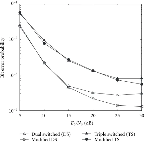
It was shown in [14] that there exists a catastrophic er-ror mode in the switched dual DIR MLSD-VA when the DIRs are either (1/√2,1/√2) or (1/√2,−1/√2). It was also shown that this error mode can be prevented using the DIRs (1/√2, α/√2) and (1/√2,−α/√2). Usingα=0.99 has been found to work well in dynamic environments. BER are shown in the appendix that demonstrate the performance improvement as a result of the suggested modification to the DIRs.
3. NEW RECEIVER ARCHITECTURE
In this section the predictive switched DIR MLSD-VA re-ceiver is introduced. This rere-ceiver is proposed to reduce the impact of the delay associated with the VA. This section starts by highlighting the relationship between delay and excess MSE in a normalised adaptive algorithm.
It was shown in [13] that the delay inherent in the con-ventional adaptive DIR MLSD-VA resulted in reduced track-ing of dynamic channels. In [13], the prefilter and DIR were updated using an adaptive algorithm. The effect of the delay in the update prefilter will now be determined in the case of a normalised adaptive algorithm. The update equation for the prefilter is
P(T)=P(T−1) +βe(T−D)R(T−D)
R(T−D)R(T−D), (4)
whereβis the normalised step size [15],R(T) is the vector of received signals at timeT, ande(T−D) is the error in (2). The MSE can be expressed as
ε(T)=e2(T)=εmin+εex(T−1), (5)
whereεminis the minimum MSE andεexis the excess MSE. Using [16, 17], it can be shown that assuming that the algo-rithm converges,εexcan be related to the delayDby
εex= βεmin
(2−β)−2Ds+s2D(D+1)−(s3/3)D(D+1)(2D+1)+· · ·,
(6) wherescan be assumed constant. It can be seen that, for con-stant step sizeβ, ifDis increased from zero, the excess mean square error also increases from zero monotonically until the denominator in (6) becomes zero. In that case,εexrapidly in-creases and the algorithm diverges. The complete derivation can be found in [12].
The concept of using prediction in adaptive MLSD is well known [5, 6, 18]. Employing a prefilter to shorten the
chan-Prefilter
Figure1: Predictive switched dual DIR MLSD-VA.
nel impulse response duration, to compensate for channel distortion, and to supply the Viterbi detector with predicted values of the input signal, was proposed in [18]. This reduces the effect of the delay associated with the VA. Figure 1 il-lustrates the structure of the proposed dual DIR predictive equaliser. Since the embedded VA operates on predicted sig-nals, the detected symbols at the output of the VA have a shorter delay.
The principle of the switched DIR MLSD-VA will be in-vestigated using Monte Carlo methods to compare the per-formance of switched fixed DIRs with adaptive DIRs in the predictive receiver strategy. The use of a switched dual DIR system implies that there will be two branches within the receiver structure that is to be tested. Similarly, there are three branches in the switched triple DIR system. The re-ceiver contains two VAs, each using one of the optimal DIRs. The use of a prefilter constrains the ECIR preceding the MLSD-VA. Each branch uses two prefilters, both prefilters have identical tap coefficients, one of the prefilters has a delay D at its input, and is used to determine the update error for the prefilter adaptation algorithm. Each branch contains a two-state Viterbi detector using one of the op-timum length-two DIRs. At each symbol interval, each of the Viterbi detectors supplies the symbol it decides upon and its associated metric to a selection device. The selec-tion device compares the metrics of the symbols from each of the two Viterbi detectors. As Euclidean distance is used to obtain the incremental metrics, the symbol with the small-est metric is chosen as the receiver output for that symbol interval. As this paper is concerned with investigating the dual DIR principle in a dynamic environment, an exponen-tial weighting factor has been incorporated into the metric calculation as
whereMj(n) is the metric of state jat time stepngiven the
transition from statekto j,Ij,k(n) is the incremental
met-ric from statekto state jat time stepn, andλis the forget-ting factor. This improves the responsiveness of the receiver to channel variations.
4. SIMULATION RESULTS
The predictive DIR MLSD-VA was tested using two types of channels, the swept notch channel and the doubly selective fading channel. To examine the tracking and switching ca-pabilities of the proposed system in the predictive architec-ture, a channel, consisting of the deterministic swept notch channel (SNC) and AWGN, was used. BER were obtained for several different systems using the predictive DIR MLSD-VA architecture with time varying frequency selective fading channels.
4.1. Tracking properties of predictive DIR MLSD-VA
systems
The SNC is a three-tap dynamic channel consisting of two zeros with a trajectory within the unit disc in the z-plane. This channel requires that the prefilter performs, in the case of length-two DIRs, its three tasks
(i) channel shortening, (ii) prediction,
(iii) reduction of distortion.
One of the zeros of the SNC moves in a clockwise direc-tion while the other moves in a counterclockwise direcdirec-tion. This results in the two zeros coinciding as they cross the real axis. Therefore, the SNC changes from being a high-pass to a low-pass channel (or vice versa) as the zeros pass through the imaginary axis. This property of the SNC makes it partic-ularly suitable in examining the tracking and switching prop-erties of the predictive dual switched system as the two opti-mal DIRs represent high and low-pass channels.
The following examples show some scenarios where the adaptive predictive DIR MLSD-VA failed and the switched dual DIR MLSD-VA was successful.
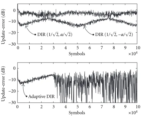
Figure 2 shows the update-error (2) for the dual switched and adaptive predictive DIR MLSD-VA systems for a chan-nel consisting of the SNC and AWGN. In this case, the SNC was implemented with the zeros having a circular trajectory of radius 0.88. The zeros were rotated around the unit disc at a constant rateπ/(5×104) radians per symbol interval.
The SNR was 10 dB. Figure 2 shows the update-error pow-ers for the adaptive and dual switched systems for 105
sym-bols. The systems were trained for the first 5×10³
sym-bols. The SNC started atπ radians and therefore the chan-nel had a low-pass characteristic. The zeros passed through the imaginary axis after 2.5×10³ symbol instants and the
channel starts to change to a high-pass channel. As the channel is low-pass initially, the (1/√2, α/√2) DIR is opti-mal and as shown in Figure 2, the update-error for the pre-filter, using (1/√2, α/√2) as a target ECIR, has the small-est error of the dual switched system. The adaptive system
0 1 2 3 4 5 6 7 8 9 10
Figure2: Update-error powers of dual switched and adaptive re-ceivers in SNC and high AWGN power environment. Parameters:
radius=0.88,dθ/dt=π/(5×104), SNR=10 dB.
converges to this DIR as shown by the adaptive update-error in Figure 2.
The update-error power for the prefilter using (1/√2,
−α/√2) is initially much larger than that of the other prefilter but as the channel approaches the transition from low-pass to high-pass, the update-error powers. As the zeros approach the imaginary axis, the update-error signals become quite noisy. The high additive noise power reduces the ability of the prefilters to have an accurate ECIR as the channel changes from low to high pass. After the transition at the 2.5×10⁴th
symbol instant, Figure 2 shows that the update-error power for the (1/√2,−α/√2) DIR branch of the switched dual sys-tem is considerably less noisy and has a smaller magnitude indicating that (1/√2,−α/√2) is the optimal DIR in this en-vironment. The update-error power of the (1/√2,−α/√2) DIR branch of the system continues to decrease as the chan-nel becomes more high pass until the 5×10⁴th symbol
in-stant, when the two zeros coincide as they cross the real axis. Then the update-error power starts to increase as the channel moves to the transition to a low-pass channel.
Figure 2 shows that the adaptive system performs poorly in this high AWGN power environment. The update-error of the adaptive system indicates that the adaptive system trained to the (1/√2, α/√2) DIR successfully. The adaptive system tracks the channel as it approaches the transition from low-pass to high-low-pass, however it fails to track the channel af-ter transition as shown in Figure 2 by the large oscillations in the error power. These oscillations in the update-error power are the result of the ECIR having collapsed to become quite small in magnitude. Figure 2 is an example of the robustness of the dual switched DIR MLSD-VA operat-ing successfully in a robust dynamic environment, where the adaptive DIR MLSD-VA failed.
chan-0 2 4 6 8 10 12
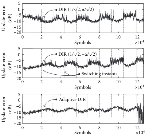
Figure3: Update-error powers of dual switched and adaptive re-ceivers for a SNC with increasing trajectory. Parameters: initial
radius =0.4, final radius=0.912,dθ/dt =π/(4×104), SNR =
9.5 dB.
nel. The deterministic channel that was used to obtain Figure 3 consists of an SNC whose zeros have a trajectory such that the channel has increasing ISI. Increased ISI is achieved by increasing the radius of the trajectory of the ze-ros. Also, the trajectory of the zeros was such that the channel remained in the vicinity of the boundary between a high-pass and a low-pass channel. This allowed for the examination of the behaviour of the switched dual system and the adaptive system in an environment where the channel was near the boundary of the two optimal DIRs.
The dual switched and adaptive systems were trained for the first 5×10³ symbols. As can be seen from Figure 3,
the channel passed through the boundary between the op-timal DIRs nine times. The two update-error powers of the dual switched system indicate the repeated transition of the channel through the imaginary axis in thez-plane. However, Figure 3 shows that the update-error power of the adaptive system is very similar to that of the update-error power of the prefilter with (1/√2,−α/√2) as DIR. This indicates that the adaptive system was unable to detect the channel transition due to the high noise power (SNR= 9.5 dB). The adaptive system was initially able to track the channel as the chan-nel ISI was low (initial radius=0.4), however as the ISI in-creased, Figure 3 shows that the adaptive system failed after the 1.2×10⁵th symbol instant (indicated by the large
os-cillations in the adaptive update-error power), yet the dual switched system continued to track successfully. Figure 3 il-lustrates an example of an environment where ISI resulted in the failure of the adaptive system yet the dual switched sys-tem was successful.
Figure 4 shows the update-error power for the dual switched DIR MLSD-VA and the adaptive DIR MLSD-VA
0 1 2 3 4 5 6 7 8
Figure4: Update-error powers of dual switched and adaptive
re-ceivers for a SNC with constant trajectory. Parameters: radius =
0.85,dθ/dt=π/(5×104), SNR=20 dB.
systems operating in a channel consisting of the determin-istic SNC and AWGN. The zeros of the SNC were moved in a circular trajectory. In this case, the channel was slowly time varying and had a low noise power. Figure 4 shows that the dual switched DIR MLSD-VA successfully tracked the chan-nel, however, the adaptive system fails to track the channel resulting in failure of the adaptive system. This was termed a catastrophic error mode in adaptive predictive DIR MLSD-VA in [19].
The ability of the proposed predictive switched dual DIR MLSD-VA to track a dynamic channel was investigated us-ing the SNC. Figures 2, 3, and 4 show examples of envi-ronments where the proposed dual system was successful in tracking the dynamic channel and the adaptive system failed. A more rigorous examination of the performance of the fixed and adaptive DIR MLSD-VA can be obtained from BER.
4.2. BER for predictive DIR MLSD-VA systems
BER were obtained for the receivers using a BPSK transmis-sion system. These were obtained for four different configu-rations of the predictive receiver:
(i) system 1 is the dual switched DIR MLSD-VA; (ii) system 2 is the length two adaptive DIR MLSD-VA; (iii) system 3 is the triple switched DIR MLSD-VA; (iv) system 4 is the length three adaptive DIR MLSD-VA.
The four systems were used so that comparison between channel shortening to length-two DIRs (as in the case of sys-tems 1 and 2) and channel shortening to length three DIRs (in the cases of systems 3 and 4) could be made. The fixed DIRs used in system 3 are listed in Section 2.
account for outdoor mobile channel characteristics at 1 GHz. Hoeher suggested that the equivalent baseband model can be written as Dirac’s delta function. Impulse responses can easily be ob-tained from (8) by independently obtaining the following:
(a) P Doppler frequencies fD,ν from a random variable
with Jakes probability density function in (−fD,max,
fD,max);
(b) Pinitial phasesθν from a uniformly distributed
ran-dom variable in [0,2π); (c) Pecho delay timesτν.
The echo delay times were exponentially distributed thus allowing the length of the power delay profile (PDP) to be de-termined by altering the decay value of the exponential dis-tribution. Only Rayleigh fading is considered throughout this paper.
To test the relative abilities of the four systems to suc-cessfully shorten a CIR, the four systems were compared us-ing samples ofc(t, τ) that had two different mean echo delay times (impulse response durations). Motivated by the fact that systems 1 and 2 have DIRs of length 2T and systems 3 and 4 have DIRs of length 3T, we used channels with mean echo delay times of 5T and 7T. The four systems were also tested using fD,max=1 Hz,3 Hz,12 Hz, and 25 Hz with each
of the two different echo delay times. In order to ensure (1) meaningful measurements of BER and (2) a satisfactory ap-proximation of the channel by a sample impulse response of c(t, τ), we used a large observation period. The channel was faded for each bit. LetBidenote theith burst containing
1.5×105bits with values from{−1,1}. The first 3×104bits
of each burst were used for training. For each BER diagram, a total of 1.3×10⁵bursts were transmitted. A signalling rate
of 7.5 MBd was used. It is important to note that the results would be significantly improved with the use of coding and interleaving.
Figures 5 and 6 show BER for the four systems being in-vestigated. The mean echo delay time (MEDT) of the chan-nels used to obtain the results in Figures 5 and 6 was 5T. Fig-ures 5a and 5b show that system 3 is the least suitable of the systems in a slowly time varying channel. Figures 6a and 6b show that as the maximum Doppler spread increases, system 2 becomes the least successful of the four systems. Figure 6a shows that at high SNR and fD,max=12 Hz, the performance
of systems 2 and 4 become almost identical. It can be seen from Figures 5 and 6 that as fD,maxincreases the most suitable
adaptive DIR changes from length 2Tto length 3T. System 1 performs considerably better than any of the other systems as the Doppler spread increases.
Figures 7 and 8 show the BER for the four systems being investigated for channels with mean echo delay times of 7T
for a range of maximum Doppler spreads. As expected, the performance of each of the systems has decreased in
com-5 10 15 20 25 30 (a) Maximum Doppler frequency=1 Hz.
5 10 15 20 25 30 (b) Maximum Doppler frequency=3 Hz.
Figure5: BER of DIR MLSD-VA, MEDT=5T.
parison to the BER for channels with mean echo delay times of 5T.
5 10 15 20 25 30 Eb/N0(dB)
10−4
10−3
10−2
10−1
100
B
it
er
ror
pr
obabilit
y
Dual switched Adaptive (L2)
Triple switched Adaptive (L3) (a) Maximum Doppler frequency=12 Hz.
5 10 15 20 25 30
Eb/N0(dB)
10−3
10−2
10−1
100
B
it
er
ror
pr
obabilit
y
Dual switched Adaptive (L2)
Triple switched Adaptive (L3) (b) Maximum Doppler frequency=25 Hz.
Figure6: BER of DIR MLSD-VA, MEDT=5T.
channels. The only observable merit in using system 3 is shown in Figures 7 and 8 in high SNR environments. Sys-tem 1 is again shown to offer the best performance of the four systems under consideration in these difficult operating conditions.
The length-two adaptive DIR MLSD-VA has a VA imple-mentation costC, the dual switched system has a VA cost 2C, the length-three adaptive system also has a VA cost of 2C, and the triple switched system has a VA cost of 6C. The BER
5 10 15 20 25 30
Eb/N0(dB)
10−4
10−3
10−2
10−1
B
it
er
ror
pr
obabilit
y
Dual switched Adaptive (L2)
Triple switched Adaptive (L3) (a) Maximum Doppler frequency=1 Hz.
5 10 15 20 25 30
Eb/N0(dB)
10−4
10−3
10−2
10−1
B
it
er
ror
pr
obabilit
y
Dual switched Adaptive (L2)
Triple switched Adaptive (L3) (b) Maximum Doppler frequency=3 Hz.
Figure7: BER of DIR MLSD-VA, MEDT=7T.
show that the dual switched DIR system offers the best per-formance for the VA cost.
5 10 15 20 25 30 Eb/N0(dB)
10−3
10−2
10−1
B
it
er
ror
pr
obabilit
y
Dual switched Adaptive (L2)
Triple switched Adaptive (L3) (a) Maximum Doppler frequency=12 Hz.
5 10 15 20 25 30
Eb/N0(dB)
10−4
10−3
10−2
10−1
B
it
er
ror
pr
obabilit
y
Dual switched Adaptive (L2)
Triple switched Adaptive (L3) (b) Maximum Doppler frequency=25 Hz.
Figure8: BER of DIR MLSD-VA, MEDT=7T.
5. CONCLUSIONS
The performance of switched DIR systems to reduce the complexity of an MLSD-VA required for a range of dynamic channels has been investigated. It is readily seen from the results that the switched dual DIR MLSD-VA exhibits supe-rior performance in each of the dynamic environments when compared with similar adaptive 2T DIR systems. For dou-bly selective multipath radio channels where the adaptive 3T
5 10 15 20 25 30
Eb/N0(dB)
10−4
10−3
10−2
10−1
B
it
er
ror
pr
obabilit
y
Dual switched (DS) Modified DS
Triple switched (TS) Modified TS
Figure A.1: BER for modified and original DIR systems with
MEDT=7T. Maximum Doppler frequency=1 Hz.
DIR system is more suitable than the adaptive 2T DIR sys-tem, BER curves show that the dual switched DIR system for the same VA implementation cost offers a considerable im-provement in performance.
The behaviour of switched dual DIR MLSD-VA and adaptive 2T DIR systems have been studied using several different channel models. It has been shown that there ex-ists a range of dynamic environments where the adaptive DIR system fails because of either ISI or high noise power. It was shown that in these dynamic environments, the dual switched DIR MLSD-VA was successful in tracking the chan-nel behaviour.
APPENDIX
5 10 15 20 25 30 Eb/N0(dB)
10−4
10−3
10−2
10−1
B
it
er
ror
pr
obabilit
y
Dual switched (DS) Modified DS
Triple switched (TS) Modified TS (a) Maximum Doppler frequency=3 Hz.
5 10 15 20 25 30
Eb/N0(dB)
10−3
10−2
10−1
B
it
er
ror
pr
obabilit
y
Dual switched (DS) Modified DS
Triple switched (TS) Modified TS (b) Maximum Doppler frequency=12 Hz.
Figure A.2: BER for modified and original DIR systems with
MEDT=7T.
REFERENCES
[1] G. D. Forney, “Maximum likelihood sequence estimation of digital sequences in the presence of intersymbol interference,”
IEEE Transactions on Information Theory, vol. 18, no. 3, pp. 363–378, 1972.
[2] S. U. H. Qureshi and E. E. Newhall, “Adaptive receiver for data
transmission over time-dispersive channels,” IEEE
Transac-tions on Information Theory, vol. 19, no. 4, pp. 448–457, 1973.
[3] D. D. Falconer and F. R. Magee Jr, “Adaptive channel memory truncation for maximum likelihood sequence estimation,”
Bell Syst. Tech. J., vol. 52, no. 9, pp. 1541–1562, 1973. [4] S. A. Fredricsson, “Optimum transmitting filter in digital
PAM systems with a Viterbi detector,” IEEE Transactions on
Information Theory, vol. 20, no. 4, pp. 479–489, 1974. [5] E. Dahlman, “New adaptive Viterbi detector for fast-fading
mobile-radio channels,”Electronics Letters, vol. 26, no. 19, pp.
1572–1573, 1990.
[6] M.-C. Chiu and C.-C. Chao, “Analysis of LMS-adaptive MLSE
equalization on multipath fading channels,”IEEE Trans.
Com-munications, vol. 44, no. 12, pp. 1684–1692, 1996.
[7] J. G. Proakis, “Adaptive equalization for TDMA digital mobile
radio,”IEEE Transactions on Vehicular Technology, vol. 40, no.
2, pp. 333–341, 1991.
[8] N. Seshadri, “Joint data and channel estimation using blind
trellis search techniques,” IEEE Trans. Communications, vol.
42, no. 2–4, pp. 1000–1011, 1994.
[9] R. Raheli, A. Polydoros, and C.-K. Tzou, “Per-survivor pro-cessing: a general approach to MLSE in uncertain
environ-ments,” IEEE Trans. Communications, vol. 43, no. 2–4, pp.
354–364, 1995.
[10] M. R. Boyle and A. D. Fagan, “Dual DIR equalisation of
dy-namic channels,” inIST 2000 Mobile Summit, pp. 719–724,
Galway, Ireland, 2000.
[11] M. R. Boyle and A. D. Fagan, “Switched DIR Viterbi
equalisa-tion for frequency selective fading channels,” inCOMCON 8,
Crete, Greece, 2001.
[12] M. R. Boyle,Switched desired impulse response maximum
like-lihood sequence detectors for dynamic channels, Ph.D. thesis, University College Dublin, Ireland, 2001.
[13] D. D. Falconer and F. R. Magee Jr, “Evaluation of
deci-sion feedback equalisation and Viterbi algorithm detection
for voiceband data transmission-Part I,” IEEE Trans.
Com-munications, vol. 4, pp. 1130–1139, October 1979.
[14] M. R. Boyle and A. D. Fagan, “Switched DIR equalisation of
dynamic channels and a degenerative error mode,” in
EURO-CON 2001, pp. 18–21, Bratislava, Slovak Republic, July 2001. [15] D. R. Morgan and S. G. Kratzer, “On a class of
computa-tionally-efficient, rapidly-converging, generalized NLMS
al-gorithms,” IEEE Signal Processing Letters, vol. 3, no. 8, pp.
245–247, 1996.
[16] R. D. Gitlin and S. B. Weinstein, “On the required tap-weight precision for digitally implemented, adaptive, mean squared
equalisers,”Bell Syst. Tech. J., vol. 58, no. 2, pp. 301–321, 1979.
[17] G. Long, F. Ling, and J. G. Proakis, “The LMS algorithm with
delayed coefficient adaptation,”IEEE Trans. Acoustics, Speech,
and Signal Processing, vol. 37, no. 9, pp. 1397–1405, 1989. [18] Y. Gu and T. Le-Ngoc, “Adaptive combined DFE/MLSE
tech-niques for ISI channels,” IEEE Trans. Communications, vol.
44, no. 7, pp. 847–857, 1996.
[19] M. R. Boyle and A. D. Fagan, “A catastrophic error mode in adaptive predictive DIR equalisation of dynamic channels,” in
SIPS 2001, Antwerp, Belgium, 2001.
[20] P. Hoeher, “A statistical discrete time model for the WSSUS
multipath channel,”IEEE Trans. Vehicular Technology, vol. 41,
Michael Boylereceived his B.Eng. degree in electronic engineering from University Col-lege Dublin in 1993. He joined the Digi-tal Signal Processing Group, University Col-lege Dublin. He received his Ph.D. in 2001. His current research interests are in the field of signal processing, equalisation, reduced complexity maximum likelihood sequence detection, and channel modelling.
Anthony D. Faganreceived the Ph.D. de-gree from University College Dublin (UCD) in 1978. He held a position as a research en-gineer at Marconi Research Laboratories, in Essex from 1977 to 1980 where he worked on digital signal processing (DSP) for ad-vanced communication systems. In 1980, he took up a position of Lecturer in the De-partment of Electronic and Electrical En-gineering at UCD where he established the