R E S E A R C H
Open Access
A wireless video multicasting scheme based
on multi-scale compressed sensing
Anhong Wang
1*, Qingdian Wu
1, Xiaoli Ma
2and Bing Zeng
3,4Abstract
Video multicast is becoming more and more popular in wireless multimedia applications, in which one major challenge is to offer heterogeneous users with a graceful degradation against varying packet loss ratios and channel noise. In this paper, we propose a multi-scale compressed sensing-based wireless video multicast scheme,
abbreviated as MCS-cast. The encoder of MCS-cast decomposes each video frame through a discrete wavelet transform (DWT) and explores an optimized compressed sensing (CS) rate to sample/measure each DWT level. The CS measurements are then packed in such a way that all packets are made as equally important as possible, while each packet includes different percentages of different DWT levels. Finally, the packets are transmitted via an analog-like modulator with mapping of the measurements into a very dense constellation. We demonstrate that because of larger percentages of more important DWT levels in each packet, packet loss leads to a much reduced influence on the reconstruction quality. Experimental results show that our MCS-cast preserves the property of graceful
degradation for heterogeneous users and can outperform the state-of-the-art SoftCast by up to 3 dB in PSNR at high packet loss ratios (over the same noisy channel).
Keywords: Multi-scale; Compressed sensing; Video multicast; Discrete wavelet transform
1 Introduction
Multicasting of video signal has recently become a pop-ular application in wireless networks, such as mobile TV, media sharing, live broadcasting of sport events, and lec-turing. Because of channel heterogeneity among multiple users (e.g., the channel bandwidth they are connected and the channel error they are suffering), one big challenge imposed to video multicast is to simultaneously guar-antee the best possible video quality for different users according to their individual channel characteristics.
In conventional wireless video multicast, a video bit-stream coded at a specific bit rate is transmitted over the wireless network. For example, the digital video broad-casting (DVB) scheme [1] transmits the bitstream com-pressed by the traditional video coding standard over a wireless channel. However, this fixed bit rate usually incurs “unfairness” to users in a multicast group: if the rate accords with a low-quality receiver, users with bet-ter channel characbet-teristics only obtain a low-quality video;
*Correspondence: [email protected]
1Institute of Digital Media and Communication, Taiyuan University of Science and Technology, No. 66, Waliu Road, Taiyuan, Shanxi, China
Full list of author information is available at the end of the article
alternatively, if the rate is selected for a high-quality user, the low-quality users cannot decode the bitstream at all. On the other hand, the conventional wireless video trans-mission schemes have another disadvantage: they are not resilient to channel errors or noise, thus leading to a sharp decrease of reconstructed video quality (the so-called cliff effect) when the channel is corrupted by noise (it is very common in practice), and the reconstructed video qual-ity will not improve even when the signal-to-noise ratio (SNR) becomes larger [2]. The emergence of the layered digital scheme alleviates the cliff effect through the com-bination of a layered video coding and a layered video transmission. Typically, scalable video coding (SVC) [3] is utilized as the layered video coding technique, and hier-archical modulation (h-mod) [4] is adopted as the layered transmission scheme. However, the layered digital scheme does not solve the cliff effect completely due to the limited number of layers, which actually generates the staircase effect.
Recently, SoftCast [2] has been proposed as a new framework to deal with the aforementioned problems, particularly the cliff effect. SoftCast sends real numbers
instead of a digital bitstream by using a very dense constel-lation, and thus it is called an analog transmission. Specif-ically, by discarding entropy coding and channel cod-ing, SoftCast consists of three steps: block-wise discrete cosine transform (DCT), power allocation, and whitening. Firstly, DCT removes the spatial correlation within each video frame; secondly, power allocation generates a com-pact and resilient representation of DCT coefficients; and finally, whitening generates the equal-importance packets that will be transmitted directly over a wireless channel. In SoftCast, reconstruction quality at each user only depends on its channel characteristic (including packet loss rate and channel SNR) so that receivers with a good channel condition can obtain better video quality, while users with a bad channel condition can still watch a lower quality. Experimental results showed that SoftCast is more robust to channel noise and achieves a smooth degradation of quality.
Several approaches have been proposed to improve the performance of SoftCast in the past few years, such as D-cast [5] and Wave-cast [6], by making use of the inter-frame correlation of video signals to remove the tem-poral correlation. Furthermore, Hybrid-Cast [7] utilizes a hybrid transmission that combines the digital trans-mission of important information (such as the motion vector and scalar factor) and SoftCast’s analog transmis-sion of the other information (including the DCT coeffi-cients). However, since the packets in Hybrid-Cast are not equally important, the performance may not be as good as expected when the important packets are lost. Mean-while, there are several works appearing in the area of soft video transmission. For instance, the bandwidth expan-sion problem of soft video coding is solved by layered coset coding [8]; a gradient-based framework is proposed in [9] for wireless soft video broadcast; the compressive sensing (CS) is integrated into input multiple-output (MIMO) transmission to make sure that the recon-structed image/video quality is commensurate with the channel SNR and the MIMO dimension [10, 11]; the mul-tipath case of the SoftCast is investigated in [12] in which high-energy DCT coefficients are assigned to a “good” subcarrier; and a real soft video broadcast system has been implemented and some PHY layer issues have been solved in [13].
The CS technique seems very suitable for wireless trans-mission (with random packet loss) due to its random measurement. One simple wireless video multicast frame-work based on CS has been presented in [14], which explores the random measurement to generate equal-importance packets, consequently eliminating the cliff effect and obtaining a graceful degradation. As for the CS technique, a few algorithms have been widely applied for image and video coding, such as the structurally random matrices (SRMs) and block-based compressed sensing
(BCS) [15, 16]. BCS is specially tailored to maintain a low computational burden. However, BCS is not efficient in compression because it wrecks the global random mea-surement. Then, MS-BCS-SPL [17] (multi-scale BCS with smooth projection Landweber) explores BCS for different levels of a wavelet-decomposed image and consequently improves the performance of BCS greatly, while retaining the low computational burden.
In this paper, we extend the state-of-the-art MS-BCS-SPL to the case of multiple users and propose a multi-scale CS-based wireless video multicast scheme: MCS-cast. Specifically, each video frame is decomposed by a multi-scale discrete wavelet transform (DWT). Then, the optimally determined CS rates are allocated to differ-ent DWT levels with an attempt of sampling the more important DWT levels with higher measurement rates. All achieved measurements are packed in such a way that all packets are equally important and each packet includes different percentages of different DWT levels. Finally, the packets are transmitted through a physical technique like SoftCast, mapping the measurements into a very dense constellation. We will demonstrate that (1) the cliff effect is avoided naturally because of application of the equal-importance packing strategy and (2) packet loss results in a (much) reduced influence on the reconstruction qual-ity because of larger percentages of more important levels in each packet. At the same time, the linear least square estimator (LLSE) is incorporated to eliminate channel noise, thus leading to a further improved performance in reconstruction quality.
2 Related works
Our work is strongly related to the theory of CS. There-fore, we first review it briefly and then discuss two extended versions of it: BCS-SPL and MS-BCS-SPL.
2.1 Conventional CS
Suppose that a signalxwith lengthNcan be represented via a known basis ∈RN×N(the inverse transform), i.e.,
where∈RNis the coefficient vector withKsignificant values in the transform domain,K N. Then, we project
x onto an M-dimensional space using a measurement matrix∈RN×N:
y=x= (2)
CS theory can solve it by anl0-constrained optimization problem:
ˆ
θ =arg min
θ θl0 s.t. y=x (3)
In practice, such al0-constrained optimization is suffer-ing from its computational infeasibility. Then, CS turns to solve anl1-based convex optimization, and the recovery is implemented directly by exploiting linear programming. Onceis obtained, we can obtainxasx=.
2.2 BCS-SPL
In BCS-SPL, an original image withN pixels and need-ing Mmeasurements is first divided into blocks of size
B×B. Then, each block is CS-sampled using the same matrixB:
yj=B·xj=B·(B·j) (4) where j andyj are, respectively, the transform coeffi-cients and measurement vector of the j-th block; yj is with size MB ×1; MB = |MN ·B2|; B ∈ RB2×B2; and B∈RMB×B
2
. Here,Bis chosen to be orthonormal, i.e., B·TB = 1. The equivalent measurement matrixfor the entire image is a block-wise diagonal one:
=
Since BCS-SPL is based on block-wise image acquisi-tion, only the measurement matrixBneeds to be stored, which greatly saves the storage space and improves the reconstruction speed. In addition, BCS-SPL combines a Wiener filter to the SPL algorithm, thus offering a much smoothed reconstruction. Afterwards, some state-of-the-art block-based CS reconstructions for images and videos, e.g. [18] and [19], were designed, and they have shown improvement over the BCS-SPL.
2.3 MS-BCS-SPL
In MS-BCS-SPL, the sampling operatoris divided into two parts, a multi-scale wavelet transform matrixand a multi-scale block-wise measurement matrix such that =, and Eq. (2) now becomes
y=x (6)
Suppose that generates L level wavelet decompo-sition. Then, the measurement matrix , composed of
Ldifferent block-wise sampling operators, is adopted to these decompositions with one operator for each level. Regarding as the expression of x in the transform domain, i.e.,=x, the sub-bandsat levellofcan be divided intoBl×Blblocks and each level will be measured through the appropriately sized l. Assume that yl,s,i is the measurement of blockiof sub-bandsat levellof,
withs ∈ {H,V,D}(standing for horizontal, vertical, and diagonal, respectively), 0≤l≤L−1, then,
yl,s,i=ll,s,i (7) Notice that we apply the same measurement matrixlto three sub-bands (H, V, and D) at the same levell.
Next, an optimized CS raterl is adjusted for each level
lin MS-BCS. Specifically, the rate of the baseband level0 (LL0 sub-band) is set to be full, i.e.,r0 = 1 (because of the highest importance), and the rate for levell(l=0) is selected asrl=wlr
so that the overall rate becomes
r= 1
If a target rater and the weightswl on each level are given,r can be determined by Eq. (8), leading to a set of level-wise CS ratesrl.
During the MS-BCS-SPL reconstruction, an iteration process called the Landweber step [20, 21] lies between the smoothing and thresholding operations in the wavelet domain. First, the constrained optimization formulation is replaced by an unconstrained optimization problem via a Lagrangian multiplier with anl2-distance penalty:
Then,is recovered by the following successive projec-tion and thresholding operaprojec-tions, assuming (0) is the initial approximation to the wavelet coefficients:
whereris a scaling factor, andJ(i)is the threshold that is used at thei-th iteration.
3 The proposed scheme
system should consider the channel noise, and the recon-struction quality should smoothly change proportionally to the packet loss ratio and channel signal-to-noise ratio (CSNR).
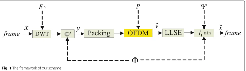
Our framework is shown in Fig. 1, where we have made use of the MS-BCS-SPL scheme. Specifically, in the encoder side, each frame is first transformed by DWT and the resulting coefficients are measured by multiplying a multi-scale measurement matrix, the same as that in Eq. (6). The measurements are packed and transmitted through a raw orthogonal frequency division multiplexing (OFDM) with an analog-like modulator to the decoders to provide wireless multicasting service. At the decoder side, the received packets at each user—the number of packets varies among different users—are first de-noised by the linear least square estimation (LLSE) algorithm, and then, each user will reconstruct a frame using the de-noised measurements.
3.1 Encoder side
Preprocessing. In our scheme, a preprocessing is per-formed to each frame before encoding in order to keep a low energy. In the original MS-BCS-SPL scheme, the image is first subtracted by its mean value (denoted asE0) of all pixels included. At the decoder side, the mean value will be added back to the image after recovering. However, in the environment of wireless video multicast, the mean value will probably be lost during transmission over a noisy and lossy channel, thus leading to a very in-accurate reconstruction. To solve this problem, we propose to set
E0 to 128 (for 8-bit video frames) at the preprocessing step. Clearly, this constant (mean) value can be compen-sated back at the decoder side (regardless of how noisy and lossy the involved channel is, because it is not needed to be transmitted at all).
DWT. In our scheme, each frame is sampled and recov-ered in the wavelet domain, following what has been done in MS-BCS-SPL [17], where a dual-tree DWT (DDWT) as [22] with bivariate shrinkage [23] is applied within the DDWT domain to enforce sparsity as described in [16].
To this end, we propose to decompose each frame (after preprocessing) into L DWT levels (as shown in Fig. 2 whereL = 4). After the DWT decomposition, it is clear that the DWT coefficients have successively decreasing importance at higher decomposition levels.
Measuring with different CS rates. Since the coeffi-cients in different DWT levels have different importance towards the reconstruction quality, we need to apply dif-ferent CS rates (for measurement) that depend on the importance at each DWT level. This means that the more important the level is, the larger measurement CS rate will be allocated to it. To this end, we first divide the sub-bands of each DWT level into blocks. We choose different sizes at different levels: the size becomes increas-ingly larger from level1to level3. Then, we will measure the sub-bands at different DWT levels with different mea-surement matrices corresponding to the block size in each level. For example, if four DWT levels are used (the same as in Fig. 2) and the block sizes 4×4, 8×8, and 16×16 are adopted, respectively, for level1∼level3, we may select the corresponding measurement matrices to be of sizes 32×16, 96×64, and 176×256, respectively, i.e.,1 ∈
R32×16at level1,2∈R96×64at level2, and3∈R176×256 at level3. Such arrangement means measurement rates of 200, 150, and 68.75 %, respectively. The over-measured CS data seem completely redundant at this moment (the cor-responding measurement rate at level0will be even larger; see discussions in the next sub-section). Nevertheless, it will be pointed out later that they are necessary when packing these CS data into packets.
Packing with optimized CS rate allocation. Packing of the CS measurements (in the DWT domain) is performed in our work in such a way that all packets have an equal importance. As a result, the reconstruction quality at each user in the multicast group depends only on how many packets are received, regardless of what packets are received. On the other hand, since the measurements from different DWT levels have different importance toward the reconstruction quality, we select different per-centages for them in each packet.
Fig. 2Four-level DWT
Suppose that (i) the width and height of each frame are
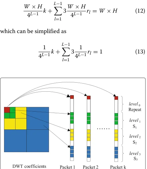
W andH, respectively; (ii) the total number of packets isk; and (iii) the overall rate for all measurements over each frame is set at full (100 %). In our scheme, we first arrange the whole baseband level0 into each packet (as shown in Fig. 3 whereL= 4), because it has the highest importance and losing it would lead to a sharply degraded reconstruction quality. Clearly, this repetition produces an over-sampling (byktimes); nevertheless, it guarantees a minimum quality even when a user receives only one packet. On the other hand, the remaining levels need to use some well-determined CS rates so as to achieve the overall rate at 100 %.
Suppose that the CS rate for level1 is rl, with l = 0,. . .,L−1, andrl ≥ rl+1. To guarantee the full overall rate, we have
W×H
4L−1 k+ L−1
l=1
3W×H
4L−1 rl=W×H (12) which can be simplified as
1 4L−1k+
L−1
l=1
3 1
4L−1rl=1 (13)
Fig. 3Illustration of packing DWT coefficients intokpackets evenly
Notice that Eq. (13) may not always be met exactly. In this case, we will chooserlproperly to make Eq. (13) hold as much as possible.
Once allrl’s are obtained (withr0 being always set at 1), each frame within a group of pictures (GOP) will be CS-sampled at the determined CS rates in the corre-sponding DWT levels. We perform the packing process on all frames within each GOP to generate a total number ofkpackets: the baseband level0is put into each packet, whereas the measurements for level1 (the total number is 3W4L×−H1 rl) is evenly put into k packets, i.e., 3W4L×−H1 rl/k CS data are put into each packet. Notice that because measurements at levell are over-complete, we need to select 3W4L×−H1 rl/k CS data carefully so that they are as independent as possible with respect to each other.
3.2 Raw OFDM channel
Before packets are transmitted over a raw OFDM chan-nel [24], the measurements in each packet are rounded and then directly mapped into the transmitted symbol, whereas no FEC of any kind is employed. Figure 4 shows the modulation adopted in our work:Ps[k]andP[sk+1] are thek-th and(k+1)-th data in thes-th packet, and such pairs of data are directly mapped as the I and Q compo-nents of the transmitted symbol. Finally, the PHY layer directly transmits all symbols over OFDM channels in which we will consider different strengths of channel noise in our experimental results.
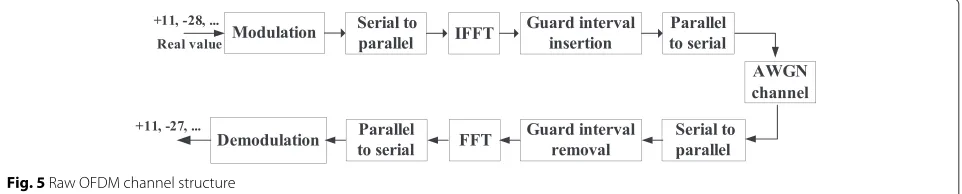
Figure 5 shows the overall OFDM channel structure in which the modulation is the same as that shown in Fig. 4. At the transmitter side, symbols obtained from modulation are inputted into some sub-bands after the serial-parallel conversion. Symbols in each sub-band go through Inverse Fast Fourier Transform (IFFT), guard interval insertion, and the parallel-serial conversion to get the OFDM signal. Then, the OFDM signal is transmit-ted over a wireless channel with additive white Gaussian noise (AWGN). At the receiver side, operations that are opposite to what have been done at the transmitter side
Fig. 5Raw OFDM channel structure
are carried out. This whole procedure is the same as in the SoftCast scheme.
3.3 Decoder side
LLSE. When packets are transmitted over a noisy channel, channel noise is added to packets and thus may incur a certain deviation from the original data, which may badly influence the reconstruction quality. Here, we propose to apply LLSE [25] to the received data before the MS-BCS-SPL reconstruction.
First, assuming that all packets are received (i.e., no packet loss) but with channel errors corrupting them, we can rewrite the received signal as
y=y+n (14)
wherenis the additive white Gaussian noise. Then, LLSE estimates the original signal as
yLLSE= y( y+)−1y (15) whereyLLSErefers to the LLSE estimate of measurementy, yis the covariance matrix ofy(which will be transmitted as metadata), andis the covariance matrix of channel noisen. With a high channel SNR (CSNR), we obtain an approximation as
yLLSE≈ y( y)−1y=y (16) This means that the LLSE step becomes void, which is reasonable because the measurements are trustable nearly completely.
Next, when a receiver experiences certain packet loss, let us definey∗ asyafter removing all lost packets, and similarlyn∗as the corresponding noise vector, and we still have
y∗=y∗+n∗ (17)
Then, the LLSE decoder becomes
yLLSE= y∗( y∗+∗)−1y∗ (18)
Different measurement matrices. Since different users are connected with different bandwidths in the same mul-ticast group, they receive different numbers of packets. Consequently, after LLSE, each user needs to use its own measurement matrix for each level according to the pack-ets it receives. Suppose that the encoder uses a random
matrix ∈ RNl (which can be repeated exactly at the decoder side) to generate the measurements for levelland one user just receivesMlfromNlmeasurements, then the corresponding measurement matrix used at the decoder side for reconstruction can be obtained as
T l = {
T
i|i∈ {1,· · ·,Ml}} (19) whereiis the row index ofand can be obtained from the packet index.
MS-BCS-SPL reconstruction. MS-BCS-SPL provides a multi-scale reconstruction by deploying block-based CS sampling within the wavelet domain, which applies the Landweber step to each block in each sub-band at each decomposition level independently. Hence, the recon-structionxl,s,j for blockjof sub-bandsat levell can be expressed as
xl,s,j=xl,s,j+Tl (yl,s,j−lxl,s,j) (20) wherelrepresents the block sampling operator of levell.
3.4 Transmission of metadata
The transmission of the standard deviation is through the traditional communication scheme consisting of entropy coding, channel coding, and modulation. The standard deviations are quantized by a 32-bit scalar quan-tizer and compressed by entropy coding, and then further coded using the 1/2 convolutional code (with genera-tor polynomials {133, 171}) and BPSK constellation. This forms the metadata packet. Hence, the percentage of this metadata is about 58×32×2/352/288=3.66 %. For this extra percentage of metadata, we just cut the measure-ment rate of level 3 to ensure the final equivalent rate of each frame to be full (100 %).
4 Simulation results
We evaluate our MCS-cast under two kinds of channel models: additive white Gaussian noise (AWGN) channel and noiseless channel. In both cases, the measurements are transmitted directly using the analog-like modulation which maps measurements into a very dense constella-tion. The packets are erased randomly with packet loss ratiopso that the number of measurements received by the decoder isM = (1− p)k, and k is the total num-ber of packets. The channel signal-to-noise ratio (CSNR) is defined as
CSNR= y22/n22
Notice that although we did not consider a real multi-cast scenario that needs to define exactly how many users are included in the multicast group, it can be mimicked closely by allowing different packet loss ratios and channel noise because each ratio/noise represents a specific user.
In our experiments, the CIF (352 × 288 at 30 Hz) video sequences ofFootball, Foreman,Coastguard,Hall, andContainerare used, and the full measurement rate is assumed. After the DWT decompositions of four levels (L = 4), except for the baseband, three remaining lev-els of each frame undergo block-based projection like that in MS-BCS. Following the example we discussed earlier in the last section, the block sizes are selected as 4×4, 8×8, and 16×16, respectively, for level1∼level3. Then, we apply random measurement matrices 1 ∈ R32×16
to level1, 2 ∈ R96×64 to level2, and3 ∈ R176×256 to level3, corresponding tor1 = 200 %, r2 = 150 %, and
r3 = 68.75 % CS rates, respectively. The total number of packets in the simulation is set tok = 8. It can be veri-fied that the overall rate is483 +3l=1 3
44−lrl= 32.532 , which exceeds 100 % a little bit. This is a very minor problem, and we can fix it easily by, for instance, cutting the mea-surement rate at level3to 66.67 % (corresponding to about 170 CS data, instead of 176 in the original setting). Such a full rate (over the whole frame) has been chosen because it is also used in the SoftCast scheme so that the com-parison is quite fair. SoftCast and our schemes have the
same transmitting power and use the same wireless band-width of 1.5 MHz considering that the number of pixels of the CIF video signal is about 3 M per second. Since we transmit complex symbols, this should require a channel bandwidth of about 1.5 MHz. Sixty-four subcarriers are used for OFDM, and the prefix duration is 16. Each packet consists of a data matrix of size 64×1584. After a 64-point IFFT, each row of data matrix is assigned to a subcarrier of OFDM randomly. Hence, the number of OFDM sym-bols in each subcarrier is 1584/2 = 792. The packets are separated by the indices of packets, and the index is inserted before each packet. We did not consider the sub-carrier for pilot data and the active sub-carriers. These exper-imental conditions are also conducted on the SoftCast scheme.
Two groups of experiments are conducted. The first one is to show the performance of LLSE in our framework. The second compares our scheme with SoftCast under the same CSNR and packet loss ratio.
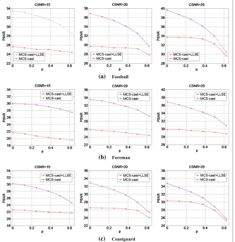
Figure 6 shows that MCS-cast with LLSE in the decoder consistently outperforms that without LLSE. This is because LLSE overcomes the negative influence of chan-nel noise to a certain degree, especially in the case of a low packet loss ratio where the gain can be as large as 7 dB. However, as the packet loss ratio increases, the gain obtained from LLSE becomes less but still quite noticeable (especially when CSNR is low).
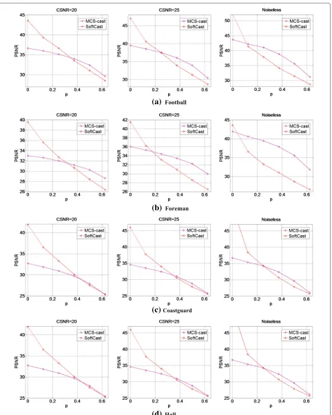
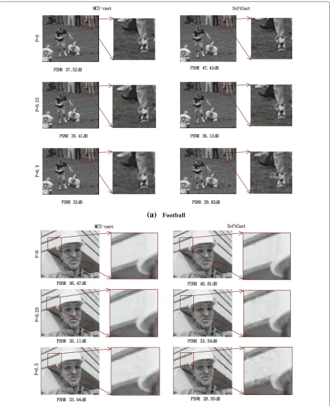
Figure 7 shows that our MCS-cast scheme consistently works better than the state-of-the-art SoftCast (both schemes have employed LLSE) when the packet loss ratio is more than 0.2 (for Football, Foreman, Hall, and Con-tainer) or 0.3 (for Coastguard). This also indicates that our scheme has better bandwidth heterogeneity. For example, the case of packet loss rate “p= 0” may mimic the user’s bandwidth of 1.5 MHz, “p = 10 %” mimics bandwidth of 1.5 MHz ×90 % = 1.35 MHz, “p = 20 %” mimics 1.5 MHz×80 %= 1.2 MHz, and so on. It is because our scheme considers the different importance of decomposi-tion levels and takes more measurements from these more important decomposition levels. More specifically, MCS-cast will preserve the baseband as long as one packet is received (which is nearly always true in practice), whereas other relatively more important information (e.g., at level1 and level3) are also likely to be received due to 200 and 150 % CS rates used in our scheme. On the other hand, in the case of no packet loss, the repeated baseband into all packets brings redundancy to our scheme, thus resulting in a lower efficiency than the referenced SoftCast.
(a)
(b)
(c)
Fig. 6Performance comparison of MCS-cast without LLSE (red circle) and with LLSE (magenta diamond) usingaFootball,bForeman, and cCoastguard as test sequences at different CSNRs and different packet loss ratios
One remark is necessary before we conclude the paper: although we did not consider a real multicast scenario that needs to define exactly how many users are included in the multicast group, it has been mimicked closely by allowing different packet loss ratios and channel noise lev-els, because each ratio/noise combination truly represents a specific user. As these combinations can be many, our MCS-cast becomes fully scalable in serving an arbitrary number of users in a multicast group or even multiple
multicast groups, where each individual user receives a number of noise-corrupted packets (depending on its channel conditions) and then runs its own reconstruction independently.
5 Conclusions
(a)
(b)
(c)
(d)
(a)
(b)
number of packets received by each user. We further proposed a novel packing strategy such that all packets are equally important and each packet includes differ-ent percdiffer-entages of measuremdiffer-ents from differdiffer-ent wavelet decomposition levels. Due to the equal-importance fea-ture in various packets and the direct transmission (with-out entropy coding and channel coding), MCS-cast does not suffer from the cliff effect and the reconstruction quality is only degraded gracefully when channel noise and/or packet loss is considered. Meanwhile, larger CS rates used at more important DWT levels guarantee that these important coefficients are still likely to be received at a user’s side even with a large packet loss ratio so that the reconstruction quality remains quite acceptable. These advantages have been clearly demonstrated in our experiments. As a future work, we will be focusing on how to utilize the correlation among adjacent frames in our MCS-cast scheme so as to make a further improvement.
Competing interests
The authors declare that they have no competing interests.
Acknowledgements
This work has been supported in part by the National Natural Science Foundation of China (No. 61272262 and No. 61210006), Shanxi Provincial Foundation for Leaders of Disciplines in Science (20111022), Shanxi Province Talent Introduction and Development Fund (2011), Shanxi Provincial Natural Science Foundation (2012011014-3), the program of “One Hundred Talented People” of Shanxi Province, Research Project Supported by Shanxi Scholarship Council of China (2014-056), and Program for New Century Excellent Talent in Universities (NCET-12-1037).
Author details
1Institute of Digital Media and Communication, Taiyuan University of Science
and Technology, No. 66, Waliu Road, Taiyuan, Shanxi, China.2Georgia Institute
of Technology, 225 North Avenue NW, Atlanta, GA, USA.3Institute of Image
Processing, University of Electronic Science and Technology of China, No. 2006 Xiyuan Ave., Chengdu, Sichuan, China.4Department of Electronic and
Computer Engineering, The Hong Kong University of Science and Technology, Clearwater Bay, Kowloon, Hong Kong, China.
Received: 28 November 2014 Accepted: 28 July 2015
References
1. U Reimers, Digital video broadcasting. IEEE Commun. Mag.36, 104–110 (1998)
2. SoftCast, One video to serve all wireless receivers. http://dspace.mit.edu/ handle/1721.1/44585
3. Wu YTH, YQ Zhang, Scalable video coding and transport over broadband wireless networks. Proc. IEEE.89, 1–20 (2001)
4. S Wang, BK Yi, inProceedings of IEEE Globecom. Optimizing enhanced hierarchical modulations. New Orleans 1–4 Dec. 2008 1–5
5. X Fan, F Wu, D Zhao, OC Au, Distributed wireless visual communication with power distortion optimization. IEEE Trans. Circ. Syst. Vi. Technol.23, 1040–1053 (2013)
6. X Fan, R Xiong, D Zhao, F Wu, inProceedings of IEEE Visual Communication and Image Processing. Wavecast: wavelet based wireless video broadcast using lossy transmission. San Diego 27–30 November 2012, 1–6 7. L Yu, H Li, W Li, Wireless scalable video coding using a hybrid
digital-analog scheme. IEEE Trans. Circ. Syst. Vi. Technol.23, 331–345 (2013)
8. X Fan, R Xiong, D Zhao, F Wu,Layered soft video broadcast for heterogeneous receivers. (IEEE Transactions on Circuits and Systems for Video Technology, 2015). DOI 10.1109/TCSVT.2015.2402831, (in press)
9. R Xiong, H Liu, S Ma, X Fan, F Wu, W Gao, inData Compression Conference (DCC). G-cast: gradient based image SoftCast for perception-friendly wireless visual communication. Snowbird, 26–28 March 2014, 133–142 10. XL Liu, C Luo, W Hu, F Wu, inINFOCOM, Orlando. Compressive broadcast
in MIMO systems with receive antenna heterogeneity. 25–30 March 2012, 3011–3015
11. XL Liu, W Hu, C Luo, F Wu, Compressive image broadcasting in MIMO systems with receiver antenna heterogeneity. Signal Process. Image Commun.29, 361–374 (2014)
12. H Cui, C Luo, CW Chen, F Wu, inProceedings of the IEEE INFOCOM. Robust uncoded video transmission over wireless fast fading channel. Toronto, 1–2 May 2014, 73–81
13. S Jakubczak, D Katabi, SoftCast: one-size-fits-all wireless video. ACM SIGCOMM Comput. Commun. Rev.41, 449–450 (2011)
14. MB Schenkel, C Luo, F Wu, P Frossard, inProceedings of Visual
Communication and Image Processing. Compressed sensing based video multicast. Huangshan, 11–14 August 2010, 1–9
15. L Gan, inProceedings of the International Conference on Digital Signal Processing. Block compressed sensing of natural images. Cardiff, 1–4 July 2007, 403–406
16. S Mun, JE Fowler, inProceedings of the IEEE International Conference on Image Processing. Block compressed sensing of images using directional transforms. Cairo, 24–26 November 2009, 3021–3024
17. E Fowler, S Mun, EW Tramel, inProceedings of the European Signal Processing Conference. Multiscale block compressed sensing with smooth projected Landweber reconstruction. Barcelona, 29–31 August 2011, 564–568
18. C Chen, EW Tramel, JE Fowler, inProceedings of the 5th Asilomar Conference on Signals, Systems, and Computers. Compressed-sensing recovery of images and video using multihypothesis predictions. Pacific Grove, 8–11 November 2011, 1193–1198
19. EW Tramel, JE Fowler, inProceedings of the IEEE Data Compression Conference. Video compressed sensing with multihypothesis. Pacific Grove, 29–31 March 2011, 193–202
20. WQ Yang, DM Spink, TA York, H McCann, An image-reconstruction algorithm based on Landweber’s iteration method for
electrical-capacitance tomography. Meas. Sci. Technol.10, 1065–1069 (1999)
21. T Blumensath, ME Davies, Iterative thresholding for sparse approximations. J Fourier Anal. Appl.14, 629–654 (2008)
22. N Kingsbury, Complex wavelets for shift invariant analysis and filtering of signals. Appl. Comput. harmonic analysis.10, 234–253 (2001)
23. L Sendur, IW Selesnick, Bivariate shrinkage functions for wavelet-based denoising exploiting interscale dependency. IEEE Trans. Sig. Process.50, 2744–2756 (2002)
24. LJ Cimini, Analysis and simulation of a digital mobile channel using orthogonal frequency division multiplexing. IEEE Trans. Commun.33, 665–675 (1985)
25. CL Lawson, RJ Hanson,Solving Least Squares Problem. (Society for Industrial and Applied Mathematics (SIAM), 1974)
Submit your manuscript to a
journal and benefi t from:
7Convenient online submission
7Rigorous peer review
7Immediate publication on acceptance
7Open access: articles freely available online
7High visibility within the fi eld
7Retaining the copyright to your article