Article
Grid-friendly Active Demand Strategy on Air
Conditioning Class Load
Jian-hong Zhu *, Juping Gu and Min Wu
Institute of Electrical Engineering, Nantong University, Nantong, 226019 JiangSu Province, China; e-mail: [email protected]; [email protected]
* Correspondence: e-mail: [email protected]; Tel.: +86-13515201945 (F.L.)
Abstract: The growing number of the accessed energy-efficient frequency conversion air conditioners is likely to generate a large number of harmonics on the power grid. The following shortage in the reactive power of peak load; hence; may trigger voltage collapse; and this conflicts with people’s expectations for a cozy environment. Concerning the problems mentioned above; an active management scheme is put forward to balance the electricity use and the normal operation of air conditioning systems. To be specific; firstly; schemes to suppress the low voltage ride through (LVRT) and harmonic are designed. Then to deaden the adverse effects caused by nonlinear group load running on the grid; and to prevent the unexpected accidents engendered from grid malfunction; the dynamic sensing information obtained by an online monitor is analyzed; which can be seen as active supervise mechanism. The combined application of active and passive filtering technology is studied as well. Thirdly; the new energy storage is accessed reliably to cope with peak-cutting or grid breaking emergencies; and the fuzzy control algorithm is researched. Finally; system feasibility is verified by functional modules co-operation simulation; and active management target is achieved under scientific and reasonable state-of-charge (SOC) management strategy
Keywords: air conditioning group load; grid friendly; active demand; storage; coordinated control
1. Introduction
As the main facility of a building, air conditioning is used by more and more enterprises and groups due to that it can provide comfortable surroundings, such as air temperature, relative humidity, cleanliness. Accompanied by increasing buildings, the number of air conditioning configurations also grows fast. This means that the demand for building energy consumption is improved continuously. Consequently, massive harmonics are appeared with lots of inverter air-conditioners (IRC) connected to the grid [1]. The high-order harmonics may cause false triggers of other load equipment, affecting the normal operation and even run out of control [2]. On the other hand, frequency conversion may increase the power loss of transmission lines, dwindle transformer power capacitors, lead to overheating of the equipment, cut down equipment utilization life and economic benefits [3].
In addition, the lack of reactive power at peak load can cause voltage fall and even lead to entire system collapse, which undoubtedly has a great impact on the normal daily life of the people. In the case that the contradiction is very prominent between power supply and demand, measures as that how to use electricity safely and improve the central air conditioning cooling or chilling water system would be imperative for the host to operate efficiently and reduce energy consumption. The maximum load capacity designed on the central air conditioning is according to the local maximum temperature of working environment by national standard. However, it works mostly at 70% of the full load, there are massive redundancy in the system designing [4]. To achieve better goals of energy saving and comfort, and minimize the impact of nonlinear load operation on grid quality, LVRT and harmonic control technology are essential. The literature[5] proposed temporary cut out measures of air condition load when receiving an emergency request from the smart grid, or to circumvent the impact of the grid by shutting down the number of cooling group through a power demand optimization scheme, which did not sacrifice too much comfort. Through coordinated scheduling of new energy equipment, the power mismatch between supply and demand of air conditioning load
is solved to the utmost extent [6], where new energy is used to achieve the goal, but the impact of air conditioning on the grid is not considered. For the nonlinear load such as air conditioning, techniques such as power factor correction rectifier are also used, but do not consider total harmonic processing on grid [7]. Therefore, from the perspective of operating characteristics of air conditioning group load, designing a grid-friendly system composed of harmonic suppression and LVRT mechanism at the load side is necessary[8]. The research on active harmonic suppression and LVRT is carried out in the following, the relevant schemes are designed, and the feasibility is verified by simulation.
2. Active Demand Strategy Design
As a thumb, among those meteorological factors that affect the comfort level of the human body, temperature is at the first place, the next is humidity, followed by which are wind direction and wind speed [9]. To make air- conditioned meet the requirements of human comfort, the water system, wind system, cold and heat source must be coordinated and properly controlled. Generally, the following objectives such as air quality (freshness), comfort (temperature, humidity, ventilate), energy saving (minimum power consumption) must be taken into account in air conditioning control. So air conditioning multi-objective working model should be expressed as Formula 1.
{
𝑠𝑠𝑑 =
(
1.818𝑡 + 18.18)(
0.88 + 0.002𝑓)
+ (𝑡 − 32) (45 − 𝑡)⁄
− 3.2𝑣 + 18.2 OPT(RAF)Min(
∑
𝑊𝑖)(1)
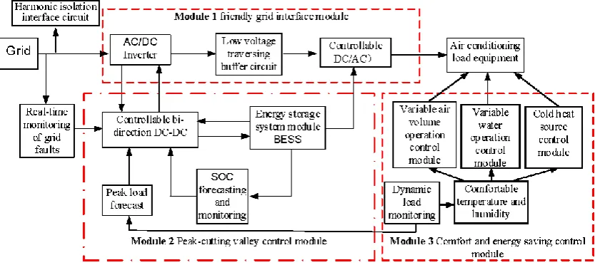
Among them, ssd is the human body comfort index [10], the formula definition of comfort level is not the same according to different classification. t is the average temperature, f is the relative humidity, and v is the wind speed. The comfort formula is an empirical formula based on long term statistics of the project. ∑ 𝑊i is the sum of energy consumed motor drag systems, 𝑊𝑖 is the energy consumed by the pump and the fan. RAF is shrink of relative air freshness, the best comfort index is 59-70 and the human body feels the most comfortable and acceptable. In the selecting process of many parameters, the average temperature t and relative humidity f can be freely selected according to the actual situation, and the wind speed v is determined according to the control demand. From the perspective of meteorology, the human body feels more comfortable when the temperature is between 18 and 20 degrees and the relative humidity is between 50% and 60%. At present, the human body comfort index adopted in Jiangsu Province has 9 grades from -4 to 4, of which level 0 is the most comfortable and most acceptable [11]. It can also be seen from the formula that the air conditioning operation is mainly the coordination work of the fans, pumps, compressors and heaters. Therefore, the air conditioning group load simulation with typical nonlinear characteristics motors group is as shown in Figure 1.
Figure 1.The module structure of active demand management.
The Z-type filter and harmonic prevention circuit are designed on the DC bus side between power supply and load. It buffers current shock whenever nonlinear load group start or sudden changes from the power grid. Grid monitor is designed so that hardware chain action can work at the same time of the severe emergency grid faults such as LVRT. The energy storage and grid power supply are switched each other by interlock linkage circuit. In addition, combined with load forecasting, battery energy storage and load peak-to-peak management, a bidirectional charge-discharge circuit is designed between the DC bus and the energy storage battery. The energy is made full useduring the LVRT period, the stored energy is released during peak hours to achieve partial peak load shift, ensure the normal operation of air conditioning. Once energy of battery is insufficient to maintain the load in normal operation at the peak state, and indoor temperature and humidity are within a certain range of the human body fitness, suspension strategy is done due to delay characteristics of the central air conditioning system. The active management technology of the group load is provided by the means of flexible huff-puff characteristics of energy storage system. On the one hand, the normal power supply under the grid fault condition is guaranteed, on the other hand, the shifting peak and valley function is realized through energy scheduling technology. Of course, key technologies such as energy storage management and converter control technology must be given as far as possible.
3. Harmonic Suppression Technology
3.1. Air conditioning group load operation characteristics
several motor models to simulate the nonlinear group load, there is still large gap compared with the actual large-scale load. If the harmonics are not processed, the consequences are serious. Therefore, it is necessary to monitor the quality of the incoming grid cur- rent by THD.
Table 1.
Maximum harmonic constraint standard of grid.
Odd order n<11 11<n<17 17<n<23 23<n<35 n>35
Harmonic 4.0% 2.0% 1.5% 0.6% 0.3%
THD <5%
3.2 Filtering technology combining active and passive filtering
Harmonic detection is the primary link to realize active filter control. The accuracy and respond speed of harmonic signal detection directly affect the compensation effect. If the detected harmonic component is not accurate, the subsequent control will meaningless. So instantaneous reactive power harmonic current detection mode and current hysteresis control mode are used [13]. Improved APF (active power filter) is used to filter out most of the harmonics, passive filter is used to filter out other small portion.
3.2.1. APF Technology
The APF is generally a DC voltage source of the inverter. The power supply here is the energy storage system. Unlike the traditional passive compensation method, the active filter injects harmonics actively. The main circuit is a controlled inverter composed of power electronic devices. By collecting the load device current, the harmonic currents are extracted to control the switch tubes. The reverse polarity harmonic current signals generated by the inverter are injected into the grid, together with the load current to eliminate unwanted components. The APF includes a main circuit module, a nonlinear load module, a harmonic detection module, and a compensation current control module. The non-linear load side is fixed up three-phase current-voltage measurement module, measurement result is input to the harmonic detection circuit module to obtain command current. Compensation current control module is used to compare and control the main circuit switching device, so to compensate the system harmonics.
1. Harmonic current detection
The harmonic current detection method is based on instantaneous reactive power [14], as shown in the Figure 2. Three-phase current in the grid are 𝑖𝑎, 𝑖𝑏, 𝑖𝑐, fundamental current are 𝑖𝑎𝑓, 𝑖𝑏𝑓, 𝑖𝑐𝑓, harmonic current are 𝑖𝑎𝑐∗ , 𝑖𝑏𝑐∗ , 𝑖𝑐𝑐∗ , power voltage is 𝑒𝑎. 𝐶𝑝𝑞 is a power-current variation matrix, LPF is low-pass filtering, and the three-phase grid voltage is converted by C3-2, and is filtered by LPF to obtain a harmonic signal followed by comparing with the fundamental wave.
Figure 2. ip-iq based harmonic detection method schematic.
2. Current hysteresis tracking control
the center, H and -H as the upper and lower limits to ensure the difference within the hysteresis range. Then the switching action of the converter is achieved. The improved technique uses a voltage-space vector double hysteresis current tracking control method to reduce both switching frequency and current tracking error at a same time [15]. Higher harmonic components can be reduced while ensure the current response speed. The voltage SVPWM (Space Vector Pulse Width Modulation) synthesizes the reference voltage vector accurately, which improves the DC voltage utilization rate while maintaining a constant switching frequency. The idea of double hysteresis current control based on space voltage vector is as Formula 2.
𝑈𝑘= 𝑅𝐼𝐶+ 𝐿 𝑑𝐼𝐶
𝑑𝑡 + 𝑒 (2)
Among them, 𝑈𝑘 is the inverter output voltage vector, 𝐼𝐶 is the corresponding output current vector, 𝑒 is terminal voltage. Error current vector ∆𝐼 is defined as the difference between current reference vector 𝐼𝐶∗ and actual output current vector 𝐼𝐶, as Formula 3.
∆𝐼 = 𝐼𝐶∗− 𝐼𝐶 (3)
Substituting Formula 3 into Formula 2, ignores effect of equivalent resistance, as Formula 4.
𝐿𝑑∆𝐼 𝑑𝑡 = (𝐿
𝑑𝐼𝐶∗
𝑑𝑡 + 𝑒) − 𝑈𝑘 (4)
Define reference voltage vector 𝑈∗, as Formula 5.
𝑈∗= 𝐿𝑑𝐼𝐶∗
𝑑𝑡 + 𝑒 (5)
Can be simplified as Formula 6.
𝐿𝑑∆𝐼 𝑑𝑡 = 𝑈
∗− 𝑈
𝑘 (6)
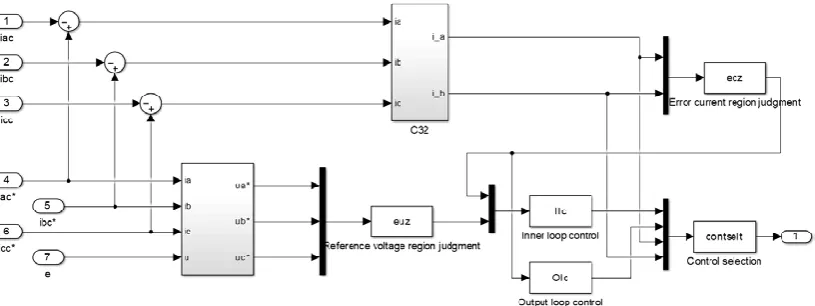
When the current error vector is in a region other than the outer loop, the current error is large. Then, fast control is required, and only the partition of the error current vector is considered. In order to rapidly reduce the current error, the central axis of the region where the error current vector is located should be selected. At this time, regardless of the reference voltage vector U ∗, U ∗− Uk will be a component that points to the origin of the coordinate along the central axis of the partition ∆I, and this component is the largest of all choices. The improved technique simulation diagram is as shown in Figure 3.
Figure 3. Improved hysteresis control simulation model.
meet the standard of 5% or less, there are still large spikes and burrs in the filtering cycle, and the waveform is not very perfect.
(a) (b)
Figure 4. (a) Current before and after filtering; (b) FFT harmonic before and after filtering.
3.2.2 Passive filtering
Passive filtering is composed of components such as capacitors, inductors and resistors. System passive filtering adopts LCL structure. The remaining frequency distribution not filtered out by APF is analyzed, RLC parameters are calculated to obtain suitable values. The cutoff frequency of the LC filter is determined firstly. It must be much smaller than the lowest harmonic frequency contained in the voltage, and at the same time much larger than the fundamental frequency [16]. The cutoff frequency is selected as following Formula 7.
10𝑓1< 𝑓𝐿< 𝑓ℎ𝑎𝑟(𝑚𝑖𝑛) (7)
𝑓1- fundamental frequency, 𝑓ℎ𝑎𝑟(𝑚𝑖𝑛)- lowest harmonic frequency. The cutoff frequency of the simulation is determined 2.25 kHz. According to the calculation,the filter capacitor 2.8210−4C, the filter inductance is 1.77610−5H. The waveforms after APF and passive filtering are as shown in Figure 4a (below) and harmonics analysis Figure 4b (below). It can be seen from the FFT analysis chart and Table 2, the total distortion rate has dropped to 2.11%, which is less than 4%.
Table 2: THD of odd harmonic before and after filter
Harmonic/number 5 7 11 13 15 17 19
Before filtering 𝑖𝑎⁄𝐴 37.94 19.81 15.12 11.48 9.50 8.07 37.94 APF filtering 𝑖𝑎⁄𝐴 3.20 2.97 3.03 3.15 3.04 2.91 3.20 Active and passive filtering 𝑖𝑎⁄𝐴 2.58 2.21 0.68 0.41 0.38 0.35 2.58
4. Active Prevention Strategy on LVRT
Based on the approximate circuit model design of the nonlinear group load of air conditioning, the energy characteristics of the load under the ideal grid condition are monitored. However, under actual conditions, the power grid is often affected by external disturbances, the short-circuit fault has the greatest impact, and the voltage will fall, which will adversely affect the electrical equipment, and even cause the damage of equipment. In general, the common method is to cut off the electrical equipment from the grid to protect the local equipment. However, with the proportion of non-linear loads increasing [17], the traditional method will cause the grid voltage and frequency to fluctuate widely, resulting in the collapse of the whole grid system. Therefore, it is more suitable for the power equipment to own LVRT capability.
4.1. Energy storage system based on isolated DC/DC converter 4.1.1. Topology of the energy storage system
In order to enable the system to have LVRT ability, the internal structure of the IRC can be skillfully utilized, and the energy storage system is added to the DC bus of the converter. The DC side and the energy storage system are joined together by a bidirectional DC converter, which is an isolated structure to achieve LVRT control, as shown in Figure 5.
Figure 5. Fuzzy adaptive PI control of energy storage
the DC bus voltage is less than the rated voltage, the converter operates in the boost mode. At this time, the switch tubes S1~S4 correspond to the diodes, which play the role of synchronous rectification. The purpose of the energy storage system to transfer energy from the push-pull circuit to the DC side is achieved by controlling the switching tubes S5 and S6. During the alternate conduction of the switch tubes S5 and S6, the energy of the energy storage element transfers energy to the left DC bus through the push-pull converter and the transformer, where the inductor L2 stores energy and the current rises. During the simultaneous conduction of S5 and S6, the inductor L2 continues to flow through S5 and S6, releasing energy and decreasing the current. Therefore, the push-pull full-bridge bidirectional converter can operate in a step-up or step-down mode according to changes in the DC-side voltage during a grid fault, maintaining the DC bus voltage in allowable range, and achieving LVRT of the entire wind power system.
4.1.2 Parameter design of energy storage system
1. Super capacitor capacity design
As the most important part of the energy storage system, the capacity configuration and parameter design of the super capacitor are very important. If the capacity setting is too small, the excess energy at the DC bus side during LVRT may not be absorbed, and the system requirement cannot be met. If the setting is too large, it may cause waste and increase economic costs. For a system with a rated power of 5 kW, the power transfer efficiency of the isolated bidirectional DC converter is about 75%. Assuming the capacitance of the super capacitor 𝐶𝑠𝑐, the initial voltage is 𝑈𝑠𝑐_𝑖𝑛𝑖𝑡, and the rated voltage 𝑈𝑠𝑐_𝑓𝑖𝑛𝑎𝑙, the charge and discharge power at the maximum instantaneous moment is expressed by Formula 8.
𝑃𝑠𝑐 𝑚𝑎𝑥≥ 𝑃𝑟 𝑚𝑎𝑥∙ 𝜂 = 5000𝑊0.75 = 3750𝑊 (8)
The rated voltage on the DC side is 540V, the super capacitor voltage is set to 150V, and the LVRT time is set to 0.4s. According to Formula 9, the capacity of the super capacitor can be deduced.
𝐶𝑠𝑐≥
2𝜂 ∙ 𝑃𝑟 𝑚𝑎𝑥∙ 𝑇𝑙𝑣𝑟𝑡 𝑈𝑠𝑐_𝑓𝑖𝑛𝑎𝑙
2 − 𝑈
𝑠𝑐_𝑖𝑛𝑖𝑡
2 =
237500.4
5402− 1502𝐹 = 11.14𝑚𝐹 (9)
Consider a certain margin, set the rated capacity of the super capacitor 12mF. Firstly, in order to make the super capacitor not overcharge or over discharge in the process of LVRT, the energy storage system is protected. Secondly, considering the current withstand capability of the power electronic device in the converter, the operating voltage is set higher. It can protect these power electronics from over-current and breakdown damage.
2.
Filter inductor 𝐿𝑠𝑐 designThe design value of filter inductance needs to meet the working requirements of both the Buck and Boost circuits [18]. At the early stage of LVRT, bidirectional DC/DC converter operates in Buck mode and is charged to the super capacitor by means of DC bus capacitors. In the recovery phase of LVRT, the bidirectional DC/DC converter operates in Boost mode, and the super capacitor is used. The constant current discharge mode feeds back the stored energy to the DC bus 𝑈𝑑𝑐. Since the average current in the loop mode is lower than the maximum current in the Buck mode, the filter inductor size can be designed according to the maximum ripple current in the loop mode of the Buck mode, as following Formula (10)
𝐿𝑠𝑐=
𝐷 ∙ (𝑈𝑑𝑐⁄ − 𝑈𝑛 𝑠𝑐_𝑖𝑛𝑖𝑡)
∆𝐼𝑠𝑐𝑝∙ 𝑓𝑠 (10)
4.2 Fuzzy Adaptive Control Strategy
Fuzzy control theory is a control strategy for studying fuzzy phenomena and belongs to nonlinear control algorithms. The main structure of fuzzy control includes fuzzification, knowledge base, fuzzy reasoning and clarity. Figure 6 shows the DC bus voltage and current waveforms of the converter before and after the energy storage configuration of the LVRT fault process.
Figure 6. DC bus voltage during LVRT with storage.
It can be seen from the waveform that the DC bus voltage is stable after the energy storage, at 540V. During the period of 0.1s-0.4s, the analog grid voltage drops, and the battery has been in discharge until grid voltage is restored at 0.4s, so the DC bus voltage is maintained stable. The battery absorbs the energy when the DC side voltage fluctuates greatly to ensure the smooth progress during LVRT. The existence of the energy storage not only ensures LVRT ability, but also reduces the voltage fluctuation at the DC bus terminal. The voltage fluctuates at 540V, and the maximum does not exceed 541V.
5. Active management energy coordination control algorithm and system simulation
Figure 7. Active demand management of group load operation coordination control flow chart.
The entire circuit simulation is as shown in Figure 8. Table 3 shows the main simulation parameters. In the system, dynamic monitoring of grid parameters is done, current and voltage are detected and analyzed.
Figure 8. Active demand simulation circuit.
Table 3. The main simulation parameters.
Components Symbols Value
Three-phase voltage/V Ua,Ub,Uc 220
Motor frequency/Hz f 50
Motor1 power/W P1 746
Motor2 power/W P2 3000
Rectifier side resistor/Ω R 10
Rectifier side inductor/H L7 0.002
APF hysteresis width/A w 0.001
PF cutoff frequency/kHz fL 2.25
Filter capacitor/F C1 2.82e-4
Filter inductor/H L2 L3 1.776e-5
Storage Super-capacitor/mF C4 12
Storage filter inductor/mH L9 10
6. Results and Discussion
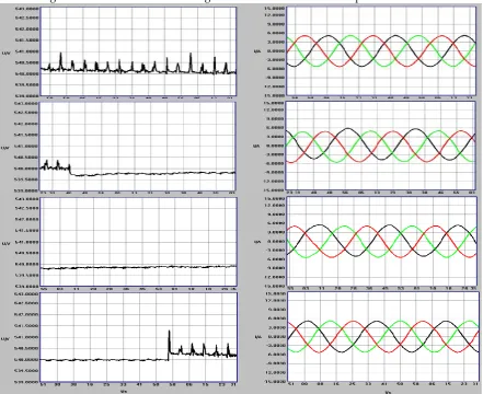
Figure 9 is voltage waveform monitored from DC bus of the energy storage interface and current waveform of the grid side. The left are voltage waveforms happened at the time of nonlinear group load normal operation, LVRT beginning, LVRT process and LVRT end respectively. The right are current waveforms that go through this process. It can be seen from the simulation results that the filter design can suppress actively the harmonics caused by the nonlinear load to the grid. With energy storage participating in grid fault control, DC bus voltage can be maintained constant when the grid LVRT occurs. Once the grid is restored, the load resumes normal grid power supply. Waveforms also show that the harmonic suppression and LVRT prevention designed can play a good role in the grid fault. Active demand management function can also be implemented.
Figure 9. Waveforms of DC bus interface voltage and current in the grid side.
1.
Research on the characteristics of the group air conditioning operation, hybrid model of the electronic circuit are determined with the similar nonlinear characteristics as the load model.2.
Research on the influence characteristics of the air conditioning load model operation on thepower grid, for the harmonic characteristics, the hybrid application of the double hysteresis active filter and the passive filter are introduced to weaken the influence of harmonics on the grid actively.
3.
In view of the influence of grid LVRT on the VFC load, an active emergency prevention mechanism with dynamic energy storage cutover is proposed to ensure the stable operation of the load.4.
According to the complex composition of the system, the sensor monitoring network strategy is proposed, and the upper dynamic monitoring design is implemented to realize the system coordination work, reduce the impact of load operation on the grid.The article totally explored an active demand energy management strategy. Based on the analysis on complex characteristics of group load operation brought to the grid, comprehensive consideration is given under such cases as the outburst faults and quality factors caused from the grid side and load side, where the special working characteristics of the energy storage system are full used, and the peaking-valley shifting requirement of the power grid is also taken into account. Correspondingly, designed control strategy is collaboratively focused on the filtering technology and energy storage technology, and the feasibility is verified by simulation. The results would have some application and promotion value. Of course, some work needs to be further studied in the research, for example, energy management of storage systems for dual hysteresis power supply and LVRT active prevention, depth study of energy-saving technology for VFC operation, and application of hybrid intelligent algorithm in harmonic processing. These will be study in the future.
7. Patents
There are Chinese invention patents resulting from the work as follows:
1.
‘Active demand strategy based on power-friendly air conditioning load side’. Authorization number: ZL201510243894.1. Authorization date: 10 /05/ 20172. ‘Effective energy-saving active demand method based on power-friendly air-conditioning load side’. Authorization number: ZL201710100461.X. Authorization date: 18 /06 /2019.
3. ‘Active demand method based on power-friendly air-conditioning load side to reduce system cost’. Authorization number: ZL201710239792.1. Authorization date: 29 /01 /2019.
4. ‘Design method of active demand energy storage for non-linear group air-conditioning group load operation’. Application Number: 2018082401656550. Now in patent actual review stage.
Author Contributions:
The articles is finished by three authors, their individual contributions are as follows: Jian-hong Zhu, methodology formal, analysis and writing—original draft preparation; Juping Gu, investigation, project administration and funding acquisition, writing—review and editing; Min Wu, software validation. All authors have read and agreed to the published version of the manuscript.
Acknowledgments:
This work is a part of the National Natural Science Foundation of China (Grant No.61673226) and the Jiangsu Provincial Department Natural Foundation of China (Grant No.15KJB470014, Grant No.18KJA470003). Nantong Science and Technology Bureau Project of China (Grant No. JC2018116).The authors would like to thank for the supports from both the Ministry of Science and Technology and National Natural Science Foundation of China.
Conflicts of Interest: The authors declare no conflict of interest.
References
2. Au, M. T.; Navamany, J. S.; Yeoh, E. C. Impact of medium power inverter-based residential harmonic loads and PFCs on low voltage lines. 2010 IEEE International Conference on Power and Energy. 2010; pp 695–699. 3. Xin, Z.; Mattavelli, P.; Yao, W. et al. Mitigation of grid-current distortion for LCL-filtered voltage-source
inverter with inverter-current feedback control. IEEE Transactions on Power Electronics 2017, 33, 6248–6261. 4. Shengwei, W. Intelligent buildings and building automation; Routledge, 2009.
5. Rui, T.; Shengwei, W.; Chengchu, Y. A direct load control strategy of centralized air-conditioning systems for building fast demand response to urgent requests of smart grids. Automation in Construction 2018, 87, 74–83.
6. Datta, A.; Bhattacharya, G.; Mukher- jee, D. et al. Modelling and simulation- based performance study of a transformer- less single-stage grid-connected photo- voltaic system in Indian ambient conditions.
International Journal of Ambient Energy 2016, 37, 172–183.
7. Lopez-Martin, V. M.; Azcondo, F. J.; Pigazo, A. Power quality enhancement in residential smart grids through power fac- tor correction stages. IEEE Transactions on industrial electronics 2018, 65, 8553– 8564. 8. Jian-hong, Z.; Ju-ping, G.; Jun, D. et al. Active demand strategy based on power friendly air conditioning
load side. 2017.
9. Yan, D.; Shu, W.; Long-zhe, J. et al. Experimental investigation and theoretical analysis of the human comfort prediction model in a confined living space. Applied Thermal Engineering 2018, 141, 61–69.
10. Hai, Y.; Shu-Yu, Z.; Wei, L. et al. Effects of deposition temperature on structure and properties of mo-doped indium oxide by radio frequency magnetron sputtering. Vacuum 2010, 85, 211–213.
11. Dui, W.; Xuejiao, D. Environmental Meteorology and Special Meteorological Forecasts. Meteorological Monthly 2000, 26(8), 3–5.
12. Zhao-an, W. Harmonic suppression and reactive power compensation; Machinery Industry Press, China, 2016.
13. Chunjie, Y.; Fang, W.; Lei, S. et al. A novel compensation current detection method for APF based on transient volt- age space vector orientation. Transactions of China Electrotechnical Society 2017, 32(7), 112–118. 14. Ke, Z.; an, L.; Xiang-yang, X. et al. An improved ip-iq harmonic current detecting method and digital
Low-pass filter’s optimized design. Proceedings of the CSEE 2007, 27(34), 96–101.
15. Harshitha, H.; Dawnee, S.; Kumaran, K. Comparative study of fixed hysteresis band current controller and adaptive hysteresis band current controller for performance analysis of induction motor. 2017 International Conference on Energy, Communication, Data Analytics and Soft Computing (ICECDS). 2017; pp 552–558. 16. Fei, L.; Xing, Z.; Hong, Z. et al. An LCL- LC filter for grid-connected converter: topology, parameter, and
analysis. IEEE Transactions on Power Electronics 2014, 30, 5067–5077.
17. Bhattacharya, D.; Biswas, S. The impacts of distributed generation on voltage stability. 2017 IEEE Calcutta Conference (CALCON). 2017; pp 105–108.