a
Corresponding author: Hamoodx8x@hotmail.com
Design & Development of a High Mass Flow Piston Synthetic Jet
Actuator
Hamad Muhammad Ashraf 1, a, Karthika Murugan Illikkal1, Francis D'souza1, Mohamed Alsayed Mahmood1, Suhail Mahmud Mostafa1, Young Hwan Kim2
1
Department of Aeronautical Engineering, Emirates Aviation University, Dubai, UAE. 2
Assistant Professor, Department of Aeronautical Engineering, Emirates Aviation University, Dubai, UAE.
Abstract. The idea of having a device that is capable of working in a systematic process allowing control of the boundary layer by means of operated on high-frequency, small-scale, and low energy actuators has caught the interest of the aerodynamicist community. With an eye on the available data and potential flow control advantages, our research team set out to manufacture a compact SJA (Synthetic Jet Actuator) of its own, which would be capable of being installed inside an airfoil. It consists of components such as a single piston cylinder, with variable exit geometry along with the control system that has an electrical actuator which can be regulated in order for it to be capable of producing various operating frequencies. This paper consists of a study into the design of a single piston device SJA and will present all significant data both theoretical and computational regarding its design and performance.
1 Introduction
The disadvantages of boundary layer separation are highly known in the aviation field. The signs of which such as loss of lift and increased drag might be straightforward to detect yet recovery is not as simple a task to undertake and may never happen leading to fatal accidents. Therefore, manipulating this phenomenon is a very sensitive topic of interest among fluid dynamics enthusiasts.
Delaying flow separation, by any means, allows for various advantageous operational benefits such as flying at higher angles of attack or reduced drag. As a result of such existing curiosity, many researches have been carried out in the hope of finding the best techniques of controlling flow separation. These techniques, so far, can be categorized into two general groups:
• Passive methods • Active methods
Active flow control dissipate energy into the free stream flow be it mechanical, thermal, or electrical. On the other hand, passive methods as the name indicated do not.
Active actuator devices are usually operated on high-frequency, small-scale, and low energy
actuators. In practical terms, there are certain merits to synthetic jets in comparison to other blowing techniques. For instance, for the latter case, the pneumatic assembly of supplying air to the wing in itself adds various complexities to the design from different aspects such as cost, weight, maintenance, and reliability. In contrast, a Synthetic Jet Actuator (SJA) can be compact enough to be fit into the wing box and operate on a semi-independent circumstance requiring least amount communication with the rest of the airplane.
2 Objectives
The main objectives that this research report would highlight are:
• Gathering the appropriate and useful data regarding the function and operation of SJA’s in order to design a new configuration.
• Identifying the critical parameters that would affect the performance of a SJA.
• Evaluating the design specifications in order to model the design. (Dimensions)
C
• Optimizing the critical parameters to reach an optimum design. (Variable Piston Head & Electric Actuator)
• Analysing the design configuration using Computational Fluid Dynamic Analyses (Ansys) • Comparing the computational results with actual
experimental results.
3 Methodology
While conducting the research into the Synthetic Jet Actuator Design and Analyses, the researchers employed various available softwares in order to model, simulate, compute and test the design. The configuration selected was modelled using
SolidWorks, and the CFD (Computational Fluid Dynamics) was performed using ANSYS. Moreover the final design was tested in Malaysia using an open test-sectioned wind tunnel and also underwent the
PIV (Particle Image Velocimetry) testing to compute the experimental data.
4 Literature Review
Since past few decades, the topic of “synthetic jet” devices has gained a lot of popularity among aerodynamicist community.
Current research in this field revolves around investigating the effectiveness of the following parameters on far-field and near-field synthetic jet behavior:
• Optimum orifice geometry • Orifice orientation
• Non-dimensional stroke length • Synthetic jet Velocity
In the literature review included in this report, all available findings about the influence of these variables are reviewed. With an eye on the available data and potential flow control advantages, our research team set out to manufacture a compact SJA of its own capable of being installed inside a 3D airfoil. Such assembly has the following components: • Single piston cylinder
• Variable exit geometry
• An electrical actuator capable of producing various frequencies.
The research methods involved in the measurement and optimization process are the usual arsenal that any aerodynamicist resorts to: CFD analysis, wind tunnel and hot wire measurement. However there was a thorough study conducted into the learning the operation of ANSYS through tutorials available from various different resources which enables the researchers to perform simulation and analyses of the design prior to the experimentation.
5 Model (SolidWorks)
The synthetic jet actuator design consists of subsystems forming the piston model along with a separate electric actuator to drive the piston and a flat stand to fit the devices on for experimental testing. The 6 independent parts making the final piston model are:
1. Changeable Heads for analyzing different orifice geometry
2. Top cylinder structure 3. Piston Head
4. Piston Shaft 5. Crank Shaft 6. Bottom Stand
Each of these subsystems was carefully optimized keeping in mind mechanic components in motion, finite mechanical spacing necessities, ring spacing and correlating dimensions for easy assembly. The spacing used between rotating and moving components to avoid physical viscosity and friction between components was 0.5cm which would improve the model’s life cycle.
After assembling a mass analysis procedure was conducted to observe the models change in center of gravity during operation. We used this trial and error balancing method to add a counter mass on the crankshaft to stabilize the device in order to perform the experiment.
Figure 2. Cylinder Configuration.
Figure 3. Piston Head Configuration.
Figure 4. Bottom Stand Configuration.
Figure 5. Head Configuration (Rectangular Orifice).
Figure 6. Piston Shaft Configuration.
Figure 7. Crank Shaft Configuration.
Figure 8. Head Configuration (Circular Orifice).
6 Computational Fluid Dynamics
The computation was performed by initially importing the top head geometries that contains the orifice (Circular & Rectangular) into ANSYS. The imported configuration was then exposed to continuous flow from below to simulate the effect of the designed piston in the cycle stage when it is blowing out the air. The dynamic nature of the device could not be analysed due to its complexity, however the cycle is systematic in nature and therefore a unidirectional continuous flow can reduce the complexity at the same time provide sufficient data regarding the operation of the device.
compute the corresponding mass flow rate and velocity of the exit flow with varying crank rotational frequencies.
The results of the flow visualization for the circular & rectangular orifice were as following:
Figure 9. Flow Visualization (Circular Slot).
The flow formation when exit from the circular orifice in Figure 9. The slot geometry causes the flow to form donut vortices. The formation of the vortices is symmetric and away from the orifice surface due to the high velocity of the exit flow corresponding to 1200rpm.
Figure 10. Velocity Distribution (Circular Slot).
The distribution of the exit flow velocity from the orifice in Figure 10. The input flow was
correspondent to 1200rpm. This led to the exit velocity reaching 106.7m/s around the orifice and gradually decreased as the perpendicular distance increased.
Figure 11. Velocity Curl (Circular Slot).
The strength of the exit flow can be analyzed by the computed velocity curl in Figure 11. On a plane parallel to the surface of the orifice, the flow is strong and symmetric around the center however the strength of the flow weakens as it spreads outwards.
Figure 12. Flow Visualization (Rectangular Slot).
of long vortices while on the other hand the width side produces comparatively smaller vortex.
Figure 13. Velocity Distribution (Rectangular Slot).
The exit velocity distribution from the orifice in Figure 13 for a rectangular slot is almost similar in trend as the circular slot; however the exit velocity is nearly double the velocity from a circular slot. This is mainly due to the difference in the exit geometry of the orifice.
Figure 14. Velocity Curl (Rectangular Slot).
The strength of the exit flow from a rectangular slot exhibits a similar trend to that of the circular slot in Figure 14, although due to the weak vortices
generated along the width side causes the center of the orifice to have concentrated strong flow in comparison.
7 Key Results
Figure 15. Mass Flow vs. Orifice Diameter Graph.
The relationship found during the computation of both the orifice (Circular & Rectangular) geometries, in regard to the change in the mass flow from the exit of the orifice to the change in the orifice diameter is non-linearly increasing in Figure 15.
Figure 16 displays the change in the mass flow with varying frequency corresponding to the RPM for both the orifice geometries. The change as computed is linear to an extend at lower frequencies, however the rate of change of the mass flow reduces as the piston frequency increases and as the theory found in the literature review stated, at a certain frequency the orifice would choke and hence lead to a constant mass flow rate.
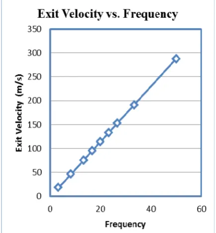
Figure 17. Exit Velocity vs. Frequency Graph.
The existing data available regarding the relationship between the Piston frequency and the exit velocity from the orifice states that it is to be linear. This is verified in the final computation performed on the imported geometries of the two orifices in Figure 17. As the frequency is increased, it is found that the exit flow velocity from the orifice increases linearly in response.
8 Manufactured Model (Experimental
Prototype)
On finalizing the design model, manufacturing process was started. The major drawbacks to this stage were the limitations on the weight and cost as well as the availability of a manufacturer willing to manufacture the final product precisely to the given dimensions.
On the other hand, the manufacturing time and material selections were other constrains that rose along this stage. However these issues were tackled accordingly within all constrains. The material selected was crucial since it would complicate the manufacturing process thereby cost rise, alongside the material select has to be evaluated based on the weight and application biases.
Material Selection:
• Cylinder - Aluminum with inner steal lining • Head - Aluminum
• Piston Head - Aluminum (Cast Iron Retainers) • Piston Shaft - Steal
• Crank Shaft - Steal • Bottom Stand - Aluminum
Figure 18. Piston Model (Front View).
Figure 19. Piston Model (Top View).
9 Conclusion
To conclude, the objectives of this research project were achieved with success. The aim was to design an actuator for experimental purposes, in order to optimize the device for later application and analysis of the synthetic jet theory. The team worked as a united body to establish proper techniques as well as literature reviews to approximate close to perfect dimensions that could be manufactured with ease; however the dimensions would later on be transferred as non-dimensional, for further study and analysis of the synthetic theory. On the other hand, difficulty was faced during the manufacturing, due to complications in taking exact dimensions as well as the manufacturing constrains. This led to a slight change in the design however the changes made did not affect the overall objective nor did it affect the calculations carried out throughout the design optimization process. The study can be used to develop new concepts and design and further improve the performance given by a SJA, the research is open to modifications since the concept is still in experimental stages.
Acknowledgments
We as researchers extend our sincere thanks to our project supervisor, lecturer and friend, Dr. Young Hwan Kim for being supportive and understanding throughout the research project. We would also be honoured to salute his patience for endurance that made us delicate our undivided attention in carrying out the project, even though we faced times of low and high, he remained there ever standing by our side.
References
1. Gilarranz J., Rediniotis K., ‘Compact, High-Power Synthetic Jet Actuators for Flow Separation Control’, Texas A&M university, AIAA-2001-0737 (2001)
2. Gilarranz J., et al, ‘Characterization of a Compact, High-Power Synthetic Jet Actuator for Flow Separation Control’, Texas A&M University, AIAA-2002-0127 (2002)
3. Mohseni K., ‘Zero-Mass Pulsatile Jets For Unmanned Underwater Vehicle Maneuvering’, University of Colorado at Boulder, AIAA
2004-6386 (2004)
4. Smith R., ‘The Influence of Orifice Orientation on the Interaction of a Synthetic Jet with a Turbulent Boundary Layer’, University of Wyoming, AIAA 2001-2774 (2001)
5. Smith R., Swift W., ‘Synthetic Jets at Large Reynolds Number and Comparison to Continuous Jets’, Los Alamos National Laboratory, AIAA 2001-3030 (2001)
6. Shuster M., Smith R., ‘A Study of the Formation and Scaling of a Synthetic Jet’, University of Wyoming, AIAA 2004-0090 (2004)
7. Traub W. et al, ‘Reconfigurable Synthetic Jet Actuation And Closed-Loop Flow Control’,Texas A&M University, AIAA 2003-217 (2003) 8. University of Alberta, ANSYS Tutorials
[http://www.mece.ualberta.ca/tutorials/ansys/] 9. ANSYS, Tutorials, Examples and Curriculum,
[http://www.ansys.com/Industries/Academic/Too ls/Curriculum+Resources/Tutorials,+Examples+ &+Curriculum]
10. ANSYS, Inc. , ANSYS Fluent 12.0 Tutorial Guide,