IJEDR1503128
International Journal of Engineering Development and Research (www.ijedr.org)1
Partial SLM using Wavelet Transform for BER
Reduction in OFDM
Saurav Pandit1, Er. Vivek Sharma2 Student1, Assistant Professor2
Bahra University, Shimla Hills, India
________________________________________________________________________________________________________
Abstract - An idea of OFDM is invented in 1966 however reached it sufficient maturity for the preparation in customare systems throughout. OFDM is the multicarrier transmission technique, in which single high rate is split into various low rate stream and is modulated mistreatment sub carrier which square measure orthogonal to every other. The high speed communication of OFDM information is meet sizable amount of the orthogonal carrier and every of the carrier is being modulated at coffee rate by the applicable spacing between the carrier they're orthogonal to every alternative. OFDM has many working like the high spectral potency, flexibility ,easy effort , lustiness to channel attenuation that create a lot of advantageous for the high speed transmission over alternative transmission technique. OFDM has Peak to Average Power Ratio that is that the main disadvantage of OFDM which degrades the performance of OFDM system
Keywords - OFDM , PAPR, Partial SLM , BER
________________________________________________________________________________________________________
I. INTRODUCTION
New technology and thereby new application square measure introducing not within the wired system however conjointly within the wireless networks. consequent generation mobile systems square measure expected to supply a considerably high rate to fulfill the wants of future high performance transmission applications. for top rate and high spectral potency new modulation theme is employed that's primarily opted by the 4G that theme is named the OFDM. The idea of OFDM is thought since 1966 however reached it sufficient maturity for preparation in customary systems throughout Nineteen Nineties[1]. OFDM is that the multicarrier transmission technique that during which within which single high rate is split into multiple low rate stream and is modulated mis-treatment sub carrier which square measure orthogonal to every other.Good answer for the high speed communication is that the OFDM through that the info is meet sizable amount of the orthogonal carrier and every of the carrier is being modulated at a rate applicable by spacing between the carrier they're orthogonal to every alternative. OFDM has many blessings like the high spectral potency, flexibility ,easy effort , lustiness to channel attenuation that create a lot of advantageous for the high speed transmission over alternative transmission technique[2]. There are several disadvantages of OFDM such as Peak to Average Power Ratio, very sensitive to frequency errors , intercarrier interferences between the sub-carriers. But OFDM has PAPR that is the main disadvantage and degrades its performance
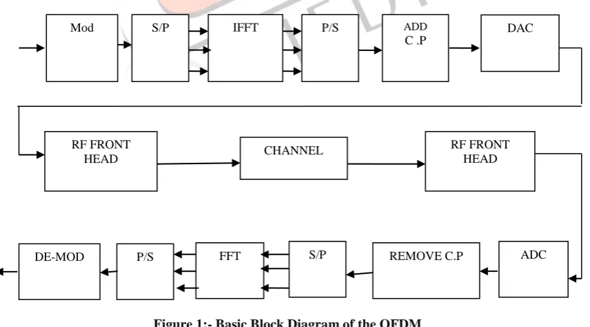
Figure 1:- Basic Block Diagram of the OFDM
Figure 1 shows the fundamental diagram of OFDM within which the input file image are supplied to the channel encoder that then mapped onto BPSK/QPSK/QAM constellation then the image is regenerate from serial knowledge to parallel knowledge by
Mod S/P IFFT P/S ADD
C .P
DAC
RF FRONT HEAD
DE-MOD P/S FFT S/P REMOVE C.P ADC RF FRONT
IJEDR1503128
International Journal of Engineering Development and Research (www.ijedr.org)2
exploitation the serial to parallel converter then by exploitation the Inverse quick Fourier remodel (IFFT) to attain the time domain OFDM signal. Time domain symbols may be described as:
𝑋𝑛= 𝐼𝐹𝐹𝑇{𝑋𝑘} (1)
𝑋𝑛= 1/𝑁 ∑𝑛−1𝑘=0𝑋𝑘𝑒
𝑗2𝜋𝑘𝑛
𝑁 ,0≤ 𝑛 ≤ 𝑁 − 1 (2)
where,
𝑋𝑘 Is the Symbol on the 𝐾𝑡ℎ sub-carriers
N is the number of subcarrier
In Figure 1 the baseband Digital signal is converted into the analog signal by the help of the Digital –to - analog convertor (DAC) Than, the analog signal. In this block the signal is up converted with the help of the mixer and amplifier and then the signal are transmitted to the antenna In Figure 1 at receiver side, the received signal is down converted to base band signal by RF frontend. The analog signal is converted into the digital signal with the help of the digital to analog convertor (ADC) Cyclic Prefix is removed from the signal in frequency domain. This step is done by the Fast Fourier Transform (FFT) block. The received symbols in the frequency domain can be represented as
𝑦(𝑘) = 𝐻(𝑘)𝑥𝑚(𝑘) + 𝑊(𝑘) (3)
where, y(k) is the received symbol on the subcarrier, H (k) is the frequency response of the channel on the same subcarrier and W (k) is the additive noise added to , subcarrier which is generally assumed to be Gaussian random variable with zero mean and variance of . Thus, simple one tap frequency domain equalizers can be employed to get the transmitted symbols. After Fast Fourier Transform (FFT) signals are de-interleaved and decoded to recover the original signal.
II. ii) PEAK TO AVERAGE POWER RATIO (PAPR)
OFDM is the multicarrier transmission technique in which single high data rate is divided into multiple low data rate stream and is modulated using sub carrier which are orthogonal to each other[1] .The major drawback in the OFDM signal is the PAPR. The PAPR of the signal s(t) can be defined as the ratio between the instantaneous Power to the Average power can be represented as the [3].
PAPR{s̅(t)} =max|𝑠̅(𝑡)|2
𝐸{|𝑠̅(𝑡)|2 (4)
PAPR occurs when in a multicarrier system the different sub-carriers are out of phase with each other At each instant they are different with respect to each other at different phase values [2]. In OFDM, PAPR causes the high peak which are larger than the typical values. High PAPR in the transmitted signal will cause the bit error rate degradation inter modulation effects on the sub carriers, energy spilling into adjacent channels and also causes non linear distortion in the power amplifiers [4].. Therefore PAPR can be calculated by using level crossing rate theorem that calculates the average number of times that the envelope of a signal crosses a given level. By calculating the complementary cumulative distribution function (CCDF) for different PAPR values can be performed that can be viewed as [5].
CCDF = Pr (PAPR > PAPR0) (5)
CCDF computes the power complementary cumulative distribution function from a time domain signal. The CCDF shows the amount of time a signal spends above the average power level of the measured signal or equivalently the probability that the signal power will be above the average power level
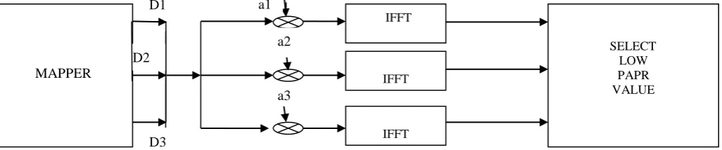
III. CONVENTIONAL TECHNIQUES 1) Selected mapping Technique (SLM)
It is scrambling technique which is used for removing PAPR in OFDM system Selected Mapping is the most efficient technique for reducing PAPR In the order to obtain original message from the receiver can get by sending the information of the of Selected Mapping technique as a side information to the receiver .
Figure 2 Selected Mapping Techniques Block diagram
MAPPER
SELECT LOW PAPR VALUE
IFFT IFFT IFFT
D1 a1
D2
D3
a2
IJEDR1503128
International Journal of Engineering Development and Research (www.ijedr.org)3
In Figure 2 shows the selected mapping in which single OFDM sequence D having length N by this number of sequence are generated that represent the information using some rotation factor and the sequence with the lowest PAPR is to be selected and transmitted . If the number of generated sequence is U called the SLM length then all the sequence are the result of multiplying the incoming original OFDM D by U different rotation factor.These factors are in the form
ai= [a 1 (i), a
2 (i), a
3
(i), … … … . , a n−1 (i) ]
(5)
where I =1 to U represent the indices of the factor and ‘a’ is the representation of the rotation factor in the vector form.
SLM has the moderate computational complexity and complexity depends upon the factor SLM length U. As the U increases the complexity also increases [7]. SLM technique does not require any limitation on the modulation technique applied in the sub carriers [8].
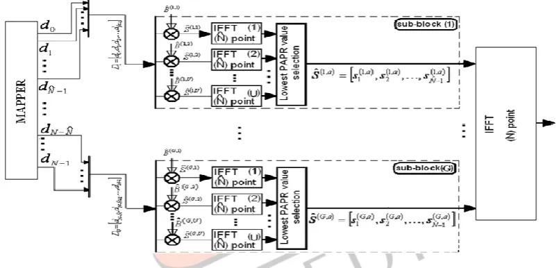
2) Partial Selected Mapping Technique Using IFFT
Based on the SLM technique a simple method has been proposed that is called the Partial Selected Mapping technique with the lower computational complexity this method has the better PAPR reduction technique then the Selected mapping technique [9]. Partial SLM can reduces the complexity to greater extend then that of the Selected Mapping technique. Partial Selected Mapping is same as that of the Selected Mapping technique but in the Partial Selected Mapping technique incoming OFDM signal is divided into number of the number of the sub sequence and then the signal is applied to the IFFT which is same as that of the Conventional Selected Mapping technique
Figure 3 Partial Selected Mapping Technique Block diagram
Figure 3 shows the block diagram of Partial Selected Mapping using the IFFT. In this incoming OFDM sequence D is divided into ‘g’ number of the sub-sequence of length𝑁̅. Then the following operation is done like Selected Mapping technique in which input sequence is multiplied in phase sequence and the signal is fed to IFFT of length 𝑁̅ [8].Since Partial SLM is same as that of Selected Mapping but the only difference is that SLM is applied ‘g’ times to each sub-block through which the U number of the sequence from single sub-sequence is to be generated and with lowest PAPR is to be selected and transmitted. This procedure is repeated till all the sub-block are covered.. The complexity of this system depends upon the following [7]
C = UNlog2N̅ (6)
Where
C= Complexity N = Total length
U= Number of generated new sequence 𝑁̅= length of new sequence
Finally all selected sequence is concatenated to form a last sequence of length 𝑁̅.and for each length 𝑁̅ ‘g’ number of partial SLM block is created. With smaller IFFT blocks used in the system the complexity is to be reduced.[8]
IJEDR1503128
International Journal of Engineering Development and Research (www.ijedr.org)4
IV. PROPOSE MODEL
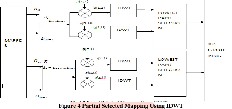
1) Partial Selected Mapping Using Wavelet Transform (IDWT and DWT)
A proposed technique is based upon Partial selected mapping technique using IFFT in which incoming OFDM sequence D is divided into ‘g’ number of sub-sequence of length𝑁̅. Then the following operation is done as Partial Selected Mapping technique using IFFT in which input sequence is multiplied in phase sequence and the signal is fed to IFFT of length𝑁̅[8]. IDWT (Inverse discrete wavelet transforms) is used because Wavelet transform does not needed any cyclic prefix which can reduces ISI and ICI. IDWT is used in transmitter side and DWT is used in receiver. The input signal is basically decompose into high pass and low pass filter then half low pass filter is reduce all the signal above the half – band frequency where high pass filter also reduces the all the signals below half band frequency with the same scale. . By two the signal is to be sub-sampled hence half of the number of the sample is to be redundant [10]
Figure 4 Partial Selected Mapping Using IDWT
Figure 4 shows Partial Selected Mapping Using IDWT. It is more reliable technique then Partial Selected Mapping using IFFT because it has less complexity then other technique used for removing the PAPR in OFDM system and increase capacity without increasing the bandwidth. In this DWT decomposes the signal into the two coefficients and signal is pass to the high and the low pass filter respectively. When the signal is passed to the low pass filter then it eliminates the all the signal above the half band frequency and when the signal is passed to high pass filter the it will pass the signal above half-band frequency and eliminates the all the signal below the with half band frequency. Since the Decomposition is expressed in term
ylow= ∑ n X[n]g[2g − 1] (7)
yHigh= ∑ n X[n]h[2g − 1] (8)
where
ylow, yHigh is the low pass filter and high pass filter
In OFDM system using wavelet transform the input signal is decomposed into the two samples then two samples are to be pass to high pass filter and low pass filter such that low pass filter will eliminate the high pass frequency and passes the low frequency whereas the high pass filter do the same operation but pass the high frequency and eliminate the low frequency
Figure 5 OFDM IDWT Modulations 2
2
In1
Out 1
In2 Even Samples
Odd Samples
IJEDR1503128
International Journal of Engineering Development and Research (www.ijedr.org)5
In Figure 5 incoming data symbol is divided into even and odd samples and then this is applied to Haar 2–Tap IDWT. Which combine two input of the signal into and there is only one output signal. In this sample of even and odd samples is employed instead of having the high and low pass filter before the IDWT is to produce the detail and coarse information. It improves timing response. Moreover noise from channel is less effective on the signal due to the signal higher instantaneous amplitude as in this case, inputs to the IDWT are two coarse signals.[11]
Figure 6 OFDM DWT De-modulation
Figure 6 shows OFDM DWT demodulator .In demodulator reverse operation is to be performed than modulator While in OFDM –DWT demodulator Haar 2-tap is executed. To compensating timing between even and odd samples delay unit is inserted before the up- sampling unit. Subsequently, two branches are added two reconstruct the original signal [11]
V. RESULT AND DISCUSSION
BER is most important aspect in communication and can be defined as bit error rate (BER) is the percentage of bits that have errors relative to the total number of bits received in a transmission, usually expressed as ten to a negative power. The BER plot is made between SNR and BER .SNR is signal to noise ratio that is measure used in science and engineering which compares the level of desired signal to the background and can be defined as signal power to noise power and expressed in db. Both the SNR and bit error rate are inverse of each other i.e. if bit error rate is higher the Signal to noise ratio is lower and vice versa and can be expressed as (1/SNR)k where, k is specific sub-carrier index
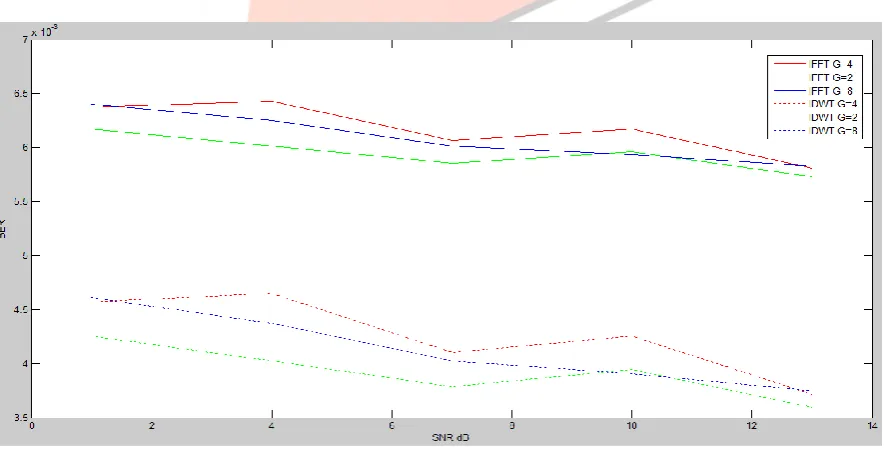
Figure 7 BER Comparisons between Partial SLM with IFFT and Partial SLM with IDWT
Figure 5.5 shows BER comparison between Partial Selected Mapping with IFFT and Partial Selected Mapping with IDWT. Above graph is plotted between BER and SNR. Bit Error Rate plot is made for different sub-division factor i.e. 2, 4, and 8 with number of sub-carriers 512 and block size is 128. In figure 10 plain line depicts plot for partial selected mapping technique using IFFT with sub-block division 2, 4, and 8, whereas dotted line in above figure illustrate BER curve for IDWT having sub-block division 2,4 and 8. Form the above figure BER curve shows that IDWT has less BER then IFFT system and performance of IDWT is better than IFFT. BER graph implies that with the increase in signal-to-noise-ratio leads to decrease in value of bit error
Out 2
2
2 Z1
+ - Up Samples
Up Samples Delay
DWT
Out 1
IJEDR1503128
International Journal of Engineering Development and Research (www.ijedr.org)6
rate due to the reduction of noise effect. From the above figure it is clear that Partial selected mapping technique using IDWT reduces BER more efficiently than conventional techniques. Because wavelet transform is has less complexity than IFFT. Wavelet transforms have main advantage of being able to separate fine details in a signal. It can also be used to decompose a signal into component wavelets
VI. CONCLUSION
In this proposed technique, the partial SLM technique along with DWT based OFDM has been used. It is an efficient technique to reduce PAPR. The main disadvantage of technique is the implementation complexity as length of SLM and number of the sub-carriers to be increased. To solve the problem, this technique is based on splitting the transmitted sequence into the sub sequences and applying SLM algorithm and wavelet transform simultaneously is proposed. Simulation results are displayed in the proposed method that performs conventional SLM technique in terms of PAPR reduction and computational complexity. The best performance in the terms of PAPR occurred when number of the division factor with complexity reduction decreases. Furthermore, complexity of proposed technique is less than of well established technique for PAPR reduction in the OFDM systems.
REFERENCES
[1] Wong, Kainam Thomas, Bingdong Wang, and J-C. Chen. "OFDM PAPR reduction by switching null subcarriers and data-subcarriers." Electronics letters47.1 (2011): 62-63.
[2] V. Vijayarangan1, R. Sukanesh, “An Overview Of Techniques For Reducing Peak To Average Power Ratio And Its Selection Criteria For Orthogonal Frequency Division Multiplexing Radio Systems” Journal of Theoretical and Applied Information Technology, 2005 – 2009.
[3] A.Dhillon, S. Singla,” An Overview of PAPR Reduction Techniques in OFDM system”,International Journal of Engineering Science and Innovative Technology (IJESIT), Volume 2, Issue 3,May 2013.
[4]S. Vimal , M.Kasiselvanathan,” A New SLM and PTS Schemes for PAPR Reduction in OFDM systems, International Journal of Advanced Research in Computer and Communication Engineering, Volume. 2, Issue 11, November 2013. [5]Md. Kislu, Md. Mojahidul, “Comparative study between Selection Mapping Technique (SLM) and Partial Transmission Sequence (PTS) for PAPR reduction in OFDM signals”, International Journal of Advanced Research in Computer and Communication Engineering .Volume-2, Issue 11, November 2013.
[6]Y.Cho, W,Yang, “MIMO-OFDM Wireless communication with Matlab.
[7] I.Hussain, “Low Complexity Partial SLM Technique For PAPR Reduction IN OFDM Transmitters”, International Journal on Electrical Engineering and Informatics - Volume 5, Number 1, March 2013.
[8] T Ahmed, F Ahmed, “Modified Selected Mapping Technique To Reduce Peak To average Power Ratio For OFDM Signals”, International Journal of Engineering Research and General Science Volume 3, Issue 3, May-June, 2015.
[9] S.HAN, J.LEE, “An Overview Of Peak-To-Average Power Ratio Reduction Techniques For Multicarrier Transmission”, IEEE Wireless Communications • April 2005
[10]J.Zakaria, M.Salleh, “Wavelet-based OFDM Analysis: BER Performance and PAPR Profile for Various Wavelets”, IEEE Symposium on Industrial Electronics and Applications, September 23-26, 2012
[11] W.Saad, "An efficient technique for OFDM system using discrete wavelet transform." Advances in Grid and Pervasive Computing. Springer Berlin Heidelberg, 2010.
[12] Bodhe, Rohit, Shirish Joshi, and Satish Narkhede. "Performance Comparison of FFT and DWT based OFDM and Selection of Mother Wavelet for OFDM."International Journal of Computer Science and Information Technologies 3.3 (2012).
[13] Asif, R., et al. "Performance comparison between DWT-OFDM and FFT-OFDM using time domain Zero forcing equalization." Telecommunications and Multimedia (TEMU), 2012 International Conference on. IEEE, 2012.
[14] Rahmatallah, Yasir, Nidhal Bouaynaya, and Seshadri Mohan. "Bit error rate performance of linear companding transforms for PAPR reduction in OFDM systems." Global Telecommunications Conference (GLOBECOM 2011), 2011 IEEE. IEEE, 2011
Author’s Profile
Saurav Pandit is pursuing M.TECH final year in department of Electronics and Communication Engineering at Bahra University, Shimla Hills .He has done his B-tech from Maharishi Markandeshwar University, Mullana (Ambala). His topic for Research is Analysis and simulation of Partial SLM in OFDM using IDWT and DWT to reduce PAPR