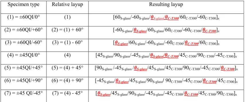
composites with pseudo-ductile behaviour in all
fi
bre orientations
Mohamad Fotouhi
a,b,*, Meisam Jalalvand
c,b, Michael R. Wisnom
b aDepartment of Design and Mathematics, University of the West of England, Bristol BS16 1QY, UKbBristol Composites Institute (ACCIS), University of Bristol, Bristol BS8 1TR, UK
cDepartment of Mechanical and Aerospace Engineering, The University of Strathclyde, 75 Montrose Street, Glasgow G1 1XJ, UK
a r t i c l e i n f o
Article history:
Received 26 May 2017 Received in revised form 19 August 2017 Accepted 21 August 2017 Available online 24 August 2017
Keywords:
Carbonfibres Glassfibres Thin-ply Hybrid composites Delamination Fragmentation
a b s t r a c t
This study exploits the potential of thin-ply carbon/glass hybrid laminates to generate high performance Quasi-Isotropic (QI) composite plates that show pseudo-ductility in allfibre orientations under tensile loading, overcoming the inherent brittleness of conventional composites. Two types of QI lay-ups with 45and 60intervals, i.e. [45/90/-45/0] and [60/-60/0], were used to fabricate novel architectures of a QI T300-carbon laminate sandwiched between the two halves of a QI S-glass laminate. The fabricated plates were then loaded in all theirfibre orientations. The laminates were designed by choosing an appropriate ratio of the carbon thickness to the laminate thickness using a robust analytical damage mode map. The experimental results verified the analytical predictions and showed a desirable pseudo-ductile failure in all thefibre orientations. Microscope images taken through the laminates thickness showed fragmen-tations (fibre fractures in the carbon layer) appearing only in the 0carbon plies. A hybrid effect was observed, with an increase in strain and stress to failure of the carbonfibres, which was found to be dependent on the stiffness of the plies separating the 0 carbon plies and the plies adjacent to the 0carbon plies. Altering the stacking sequence changes the stiffness of the separator and adjacent plies, therefore, leads to changes in the pseudo-ductile characteristics such as the initiation andfinal failure strains.
©2017 The Authors. Published by Elsevier Ltd. This is an open access article under the CC BY license (http://creativecommons.org/licenses/by/4.0/).
1. Introduction
Polymer-matrix composites use has been continuously increased in engineering applications due to their superior me-chanical properties. However, polymer composites show sudden brittle failure, with linear elastic response and little warning before failure. This drawback leads to large values of safety factors in their design.
Hybridisation of different types offibres is one of the methods that can introduce gradual failure in composite materials[1e13]. Possible failure modes in a three-layer Uni-Directional (UD) hybrid laminate made from High Strain Material (HSM) and Low Strain Material (LSM) are illustrated schematically inFig. 1. Two types of catastrophic failure modes occur in conventional hybrid compos-ites; a) a single crack through the whole thickness of the laminate
due to a high ratio of LSM to HSM thickness (improperly sized hybrid laminate), which results in a linear stress-strain curve (Fig. 1a, and b) a single fracture in the LSM instantaneously fol-lowed by unstable delamination, which appears on the stresse -strain graphs as a significant load drop (Fig. 1b). This is a typical failure mode in conventional standard ply thickness hybrid lami-nates.Fig. 1c shows a desired gradual failure where delamination is suppressed and multiple LSM fractures are obtained followed by stable localised pull-out. This desired pseudo-ductile behaviour is achievable by selecting appropriate material properties, appro-priate values of relative thickness (i.e. proportion of the LSM to HSM) and absolute thickness of the LSM. Thin carbon plies have superior mechanical properties and lower energy release rates, delaying the propagation of intra- and interlaminar cracks[14e16]. Recently, thin-ply UD and QI hybrids with different types of low strain and high strainfibres were introduced that generated the desired nonlinear stressestrain response and pseudo-ductility that avoids the catastrophic failure in laminated composites[17e19].
Fig. 2shows four main features of a pseudo-ductile laminate with a thin layer of low strainfibre plies; (i) Pseudo-yield strain
*Corresponding author. Department of Design and Mathematics, University of the West of England, Bristol BS16 1QY, UK.
E-mail address:[email protected](M. Fotouhi).
https://doi.org/10.1016/j.compscitech.2017.08.024
(3py), (ii)final failure strain (3f), (iii) Pseudo-ductile strain (3pd) and
(iv) Hybrid effect. 3pyand
s
pyare the strain and stress levels at which the tensile response deviates from the initial linear elastic behaviour, respectively. 3f ands
fare the final failure strain and stress values at which the HSM cannot carry any more load, respectively. It usually corresponds withfibre failure in the high strain material. Pseudo-ductile strain is the enhancement in strain achieved as a result of gradual failure and is calculated as the dif-ference between thefinal failure strain, and the elastic strain based on the initial modulus at thefinal failure stress.Hybrid effects were reported by different researchers[9e11], where they observed higher strain to failure of carbon in their UD glass/carbon hybrids than that of all carbon specimens. Swolfs et al. [20]reviewed the basic mechanisms causing the hybrid effect, with the most significant considered to be thermal residual stresses, altered failure development due to statistical effects on formation of clusters of fibre breaks and dynamic stress concentrations. Wisnom et al. [21] used glass/carbon hybrid composites, rather than all carbon composites, to measure the strain to failure of the baseline carbon plies more accurately, to reduce the variability typically obtained using conventional unidirectional tests and avoid the high values for the hybrid effect values when using these tests as the baseline[9e11]. This method addressed the difficulty in measuring the strain to failure due to stress concentrations at the
load introduction regions. They defined hybrid effect as the enhancement in strain and stress to failure of the low strainfibres in the thin-ply hybrid composite, compared to those obtained in hybrid specimens with thick carbon plies where it was found that there is no hybrid effect.
The performance of the pseudo-ductile QI layups is influenced not only by the UD laminates' design parameters, but also by the stacking sequence of the plies. Recently, two different stacking approaches were used to fabricate pseudo-ductile hybrids to make a QI hybrid laminate; (i) orientation-blocked method, where the hybrid laminates were fabricated from optimised UD hybrid sub-laminates [22] and (ii) orientation-dispersed method in which the hybrid laminates were made from different non-hybrid multi-directional sub-laminates[23]. A nonlinear stressestrain response was achieved in both cases, however, using the orientation-blocked concept, there were significant free-edge delaminations. The orientation-dispersed method is considerably better to decrease interlaminar stresses at the free-edges and to suppress free-edge delamination[23].
[image:2.595.142.458.72.191.2]Previous studies indicated that the pseudo-ductility is achieved in the QI hybrids in one loading orientation when subjected to tension[22,23]. However, most composite structures are subjected to multiple loading orientations, therefore, the aim of this paper is to study the potential of thin-ply carbon/glass hybrid laminates and
Fig. 1.Possible failure modes in a three layer UD hybrid made from HSM and LSM (red lines show fracture) (a) single crack through the whole specimen, (b) single crack in the LSM
followed by instantaneous delamination, and (c) multiple fracture and localised stable pull-out of the LSM. (For interpretation of the references to colour in thisfigure legend, the reader is referred to the web version of this article.)
[image:2.595.97.492.531.726.2]hybrids that fail in a gradual manner when loaded in different directions-avoiding catastrophic failure and free-edge delamination.
2. Experimental procedures
2.1. Materials and specimen design
As listed inTable 1, the HSM is standard thickness UD S-glass/ 913 epoxy prepreg supplied by Hexcel and the LSM is thin carbon prepreg (SkyFlex USN020A) from SK Chemicals (South Korea) that has T300 carbonfibres made by Toray. Please note that these are different from the TR30fibres in prepreg with the same manufac-turer's designation tested previously [19]. The corresponding
laminates can be studied.
The layups were chosen using appropriate values of relative thickness (i.e. proportion of the low strainfibre plies) and absolute thickness of the carbon fibre plies. Pseudo-ductile response is achieved by suppression of catastrophic delamination and appearance of damage modes of (i) fragmentation in the carbon plies and (ii) local delamination, before thefinal failure of the high strain glass plies. This has been done through using damage mode maps, similar to those for UD laminates[18]. These show how the damage depends on the relative and absolute thickness of the different materials. To do so, the multi-directional glass and carbon sub-laminates were assumed to be homogenised before crack development. Cracks are assumed to propagate through the thick-ness of the whole carbon epoxy laminate. The equivalent in-plane
Table 1
Characteristics of the prepregs andfibres applied.
Prepreg type S-glass/epoxy[18] USN020A (T300/epoxy)[17]
Fibre modulus E (GPa) 88 230b
Fibre failure strain (%) 5.5 1.5
Cured nominal thickness (mm) 0.155 0.029
Fibre mass per unit area (g/m2) 190 21
Fibre volume fraction (%) 50.0 40.5
E1 (GPa) 45.7 101.7
E2 (GPa) 15.4a 6.0c
G12 (GPa) 4.34a 2.40c
V12 0.3a 0.3c
Equivalent in-plane stiffness for QI (GPa) 15.2 37.8
aAssumed to be equal to E-glass properties used in Ref.[24]. bThis value is based on T300 Data Sheet[25].
[image:3.595.76.528.380.487.2] [image:3.595.89.517.557.735.2]c The transverse properties were assumed to be equal to the similar USN020A prepreg utilised in Ref.[26], as the data was not available.
Table 2
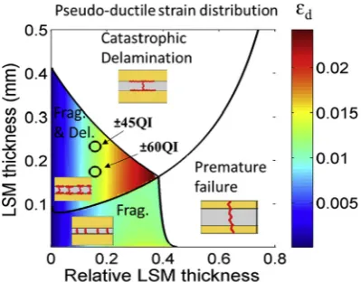
moduli of both glass and carbon QI laminates, calculated using Classical Laminate Theory, are given inTable 1. The failure strain of the homogenised materials is assumed to be equal to the fibre failure strain of the 0layers. This is an acceptable assumption as the stiffness reduction in the deterioration process of the homo-genised QI laminate is mainly due to 0carbon layer fragmentation and the final failure of the QI glass is because of 0 layer glass failure. Although this assumption may not be completely accurate one due to hybrid effects, it is a reasonable basis to design the configurations. Most of the strength and stiffness of each layer is coming from the 0layers and fragmentation/failure of this layer means a big drop in the stiffness of the remaining parts or failure of the whole laminate. Interfacial fracture toughness between the glass and carbon layers, GIIc, was assumed to be 1 N/mm[18]. The damage mode map with calculated boundaries between the different regions is illustrated inFig. 4, for the investigated±60QI and±45QI specimens. The thickness and proportion of carbon plies in the investigated hybrid layups were chosen to be in the Frag-mentation and dispersed Delamination (Frag.&Del.) region to get the desired damage scenario.
2.2. Specimen manufacturing
The laminates were cured in an autoclave at the recommended cure temperature and pressure cycle for the Hexcel 913 resin (60 min at 125C, 0.7 MPa), which was also satisfactory for the carbon. Specimens were cut using a diamond-cutting wheel. The nominal specimen dimensions were 240/160/20/h mm overall length/free length/width/variable thickness respectively. End tabs made of 2 mm thick woven glass/epoxy plates supplied by Heathcotes Co. Ltd. were bonded to the specimens using a two component Araldite 2000 A/B epoxy adhesive supplied by Hunts-man, the components were mixed with the volume fraction ratio of 100: 50 for A: B respectively and cured for 120 min at 80C inside a Carbolite oven. Thefinal samples were visually inspected to assure appropriate quality. Good integrity of the hybrid laminates was confirmed during testing procedures and no phase separation was observed.
2.3. Test procedure
Tensile testing of the hybrid laminates was performed under uniaxial tensile loading and displacement control using a crosshead speed of 2 mm/min on a computer controlled Instron 8801 type 100 kN rated universal hydraulic test machine with wedge-type hydraulic grips. A 25 kN load cell was used for better resolution in the expected load range. At least 6 specimens of each type were tested to check the repeatability of the results. To measure the strains over a nominal gauge length of 130 mm, an Imetrum video gauge system was used by tracking a dotted pattern applied on the specimen face.
3. Results and discussion
3.1. Overall mechanical results
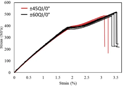
[image:4.595.128.459.66.282.2]The desired pseudo-ductile response was achieved, with consistent stress-strain curves, without any catastrophic delami-nation and with obvious plateau as illustrated in Figs. 5e7. The carbonfibres started to fragment near the knee-point which was
Fig. 3.Schematic of the investigated laminates in a QI composite plate, the red arrows showing the loading directions. (For interpretation of the references to colour in thisfigure
legend, the reader is referred to the web version of this article.)
Fig. 4.Distribution of pseudo-ductile strain for the investigated±60QI and±45QI
[image:4.595.59.259.562.718.2]then followed by a plateau due to stable progressive carbon plies fragmentation and local delamination of the carbon fragments. After the plateau, the stress started to increase as fragmentation was fully saturated, the contribution of the carbon plies to the specimen stiffness was diminished and the glass plies carried most
[image:5.595.62.538.64.560.2]of the increase in load. The failure behaviour was in good agree-ment with that expected from the design considerations. It should be noted that the hybrid effect is not considered in the damage mode map results shown inFig. 4, and the manufacturer's quoted failure strain for T300 carbon (1.5%) was used for the calculations. Table 3gives some of the important features of the curve such as the initial elastic modulus, pseudo-yield strain, and pseudo-ductile strain of these hybrid configurations. Pseudo-yield strain values were defined as the intersection of two linesfitted to the stress-strain graph before and after the fragmentation initiation point. The elastic response of the layups is identical, as expected; how-ever, due to different hybrid effects, the average pseudo-yield strains and the average pseudo-yield stresses are slightly different.
3.2. Hybrid effect
[image:5.595.84.532.68.233.2]It has been shown that the hybrid effect is strongly dependent on the ply thickness in UD hybrids [16]. As will be discussed in Section 3.3, the fragmentations appeared only in the 0 carbon plies. The thickness of single 0carbon plies is the same for the ±45QI and±60QI laminates, however they have different hybrid effects due to the different parameters such as numbers and stacking sequences of plies in the investigated configurations. The stiffness of the plies separating the two 0carbon plies on either
[image:5.595.79.530.270.447.2]Fig. 5.Results of the tensile tests for the±60QI specimens.
Fig. 6.Results of the tensile tests for the±45QI specimens.
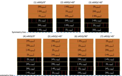
[image:5.595.49.290.486.654.2]side of the symmetry plane and the stiffness of the outer plies adjacent to the 0carbon plies are different for the various tested configurations, as illustrated schematically inFig. 8. The stiffnesses of the separator plies and the adjacent plies are worked out using the mechanical properties listed inTable 1and reported inTable 3. These stiffness values are evaluated by multiplying the modulus of the separator plies along the loading direction by the thickness of the plies. The shear deformation is constrained by the rest of the laminate, therefore, the longitudinal stiffness of the unbalanced 45s and 60splies are considered to be the same as the balanced±45s and±60splies, respectively. Since both the adjacent and separator plies are thought to influence the behaviour, a further column is included inTable 3where these are added together. Although this is somewhat arbitrary, it does facilitate a comparison of their poten-tial combined effect. For the±60QI/0and±45QI/0laminates, the
[image:6.595.32.553.84.249.2]nearby 0glass ply has a significantly higher stiffness compared to the off-axis glass layers. So, when it is next to the fragmenting 0carbon layer, the stress concentration at a single carbonfibre break would be lower as the glass ply can significantly contribute to carrying load around a subcritical cluster of brokenfibres[21]. This explains the highest average pseudo-yield strain in the ±60QI/ 0(1.80%) and the±45QI/0(1.90%) specimens. These strain values are significantly higher than the manufacturer's quoted 1.5% failure strain[25]and the pseudo-yield strain values for the other con-figurations listed inTable 3. The higher pseudo-yield strain in the ±45QI/0laminate, compared to the±60QI/0laminate, is due to the thicker, stiffer and stronger separator laminate between the two 0plies in these specimens. The higher ratio of the stiff 0glass layer to the overall thickness in the±60QI/0results in a higher final failure strain, compared to the ±45QI/0 laminate. More
Table 3
Summary of the test results for the hybrid specimens.
Specimen type Initial in-plane elastic modulus (GPa) Stiffness (modulus) of the plies separating 0carbon plies N/mm (GPa)
Stiffness (modulus) of the outer ply adjacent to the 0carbon ply N/ mm (GPa)
Sum of the stiffness of the separator and adjacent layers N/ mm Pseudo-yield stress (MPa) Relative stress-based hybrid effect (MPa) Pseudo-yield strain (%) Relative strain-based hybrid effect (%) Pseudo -ductile strain (%) Final failure strain (%) Final failure stress (MPa)
±60QI/0 23.5±0.1 682 (5.88) 7083 (45.7) 7765 379±6 45 (13.5%) 1.80±0.02 0.2 (12.5%) 1.30±0.05 3.5±0.10 504±18 ±60QI/
þ60
23.1±0.2 e 170 (5.88) 170 334±3 Reference 1.60±0.04 Reference 1.15±0.10 2.95±0.15 436±14
± 60QI/-60
23.2±0.1 341 (5.88) 170 (5.88) 511 335±7 1 (0.29%) 1.60±0.02 0 1.20±0.06 3.2±0.10 464±16
±45QI/0 23.4±0.1 2875 (16.52) 7083 (45.7) 9958 385±7 51 (15%) 1.90±0.03 0.3 (18.75%)
0.95±0.06 3.10±0.10 484±8
±45QI/ þ45
23.3±0.1 e 256 (8.84) 256 335±2 1 (0.29%) 1.65±0.02 0.05 (3.13%)
1.05±0.10 3.01±0.22 441±23
±45QI/ þ90
23.2±0.2 512 (8.84) 256 (8.84) 768 333±5e 1.62±0.04 0.02 (1.25%)
1.46±0.10 3.06±0.20 343±74
±45 QI/-45
23.3±0.2 1786 (15.38) 256 (8.84) 2042 350±4 16 (4.8%) 1.70±0.03 0.1 (6.25%) 0.96±0.05 3.05±0.15 441±11
Fig. 8.Schematic of the investigated layups, the red lines on the 0carbon plies are representative of fragmentations. (For interpretation of the references to colour in thisfigure
[image:6.595.83.504.455.716.2]details can be found in Ref.[23].
For the other±60QI and±45QI laminates, the 0carbon sub-laminate is adjacent to the ±60 and ±45 carbon layers with lower stiffness in the loading direction, respectively. Therefore, as listed inTable 3, the pseudo-yield strain values for these laminates is lower than the±60QI/0and±45QI/0laminates.Table 3shows the different values for the hybrid effect of the investigated con-figurations. These values are measured relative to the±60QI/þ60 laminate that has the lowest hybrid effect. The pseudo-yield strain of±60QI/þ60(1.6%) is higher than the manufacturer's quoted 1.5% failure strain[26]. The reason for this higher value is partially as a result of eliminating stress concentrations at the grips using the hybrid configuration that results in consistent gauge length fail-ures, but may include a small hybrid effect as the 0plies are still quite thin. Using the failure strain of±60QI/þ60as the reference allows a comparison of the relative hybrid effects between the
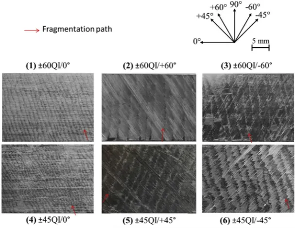
[image:7.595.45.291.68.243.2]Similar results were obtained for all the investigated specimens. Fig. 10shows the fragmentation pattern in the 0carbon layer over the width of the investigated layups after removing the top layers. The highest fragmentation crack density and pseudo-yield strain value (1.9%) with the smallest average fragmentation spacing is observed in the±45QI/0laminate which is believed to be due to the high combined stiffness of both the separator and adjacent plies (9958 N/mm). The ±60QI/0 laminate has the second-highest fragmentation cracks density and pseudo-yield strain value (1.8%) with the second-highest combined stiffness value (7765 N/mm). The±45QI/-45laminate has the third-highest combined stiffness value (2042 N/mm) and the third-highest pseudo-yield strain value (1.7%). The other ±60QI and±45QI laminates, have significantly lower combined stiffness values compared with the±60QI/0and ±45QI/0laminates. As a result, the fragmentation cracks densities in these laminates are lower than the±60QI/0and±45QI/0 lam-inates. Another interesting observation is the angle of the oblique cracks in the 0carbon layer. As shown inFig. 10, the overall frag-mentation path angle is oblique, and it is affected by the other carbon layers adjacent to the 0carbon layer. The oblique angle is between the transverse direction and the orientation of the inner adjacent carbon layer. When the 0carbon plies are in the mid-plane, the oblique angle is between the transverse direction and the orientation of the layers adjacent to the 0carbon plies.
The location of the fragmentations in the investigated laminates are illustrated schematically inFig. 8. By changing the location of
Fig. 9.Microscopy pictures from the polished surface of the±60QI/-60laminate at
[image:7.595.151.455.492.727.2]different depths through the thickness a) the60carbon ply with no fragmentation, b) theþ60carbon ply with no fragmentation, c) the 0carbon ply with fragmentation and d) the 0carbon ply, microscopy picture with higher zoom.
the 0carbon plies, the damage location and mechanisms change, and as a result, the appearances of the laminates are different from each other as shown inFig. 11. For the±60QI/0and±60QI/-60 laminates, due to the translucent nature of the glass/epoxy com-posite on the outside of the hybrid laminate, well bonded areas appear to be black and clear oblique cracks are visible due to the fragmentations and dispersed delamination. However, the frag-mentations in the±60QI/þ60laminate are hidden by the other carbon layers, which were laid on top of the fragmented plies, and no visible crack (the surface colour change) was distinguished. The finer damage pattern in the±45 QI/0, illustrated inFig. 10, is hardly visible through the thick glass layers (Fig. 11(5)). For the±45 QI/-45and±45 QI/þ45, the carbon plies covering the fragmentations hindered the visibility of the damage (Fig. 11(6), (8)). The 90glass layer is on the top of the ±45 QI/þ45 laminate and the matrix cracking is clearly observable parallel to thefibres in this layer. It will be shown that the energy release rates are significantly higher in the±45QI/þ90laminate, compared with the other laminates, which caused free-edge delaminations, just after a few carbon ply fragmentations, and resulted in the different appearance (Fig. 11 (7)) and the lowestfinal failure stress value (Fig. 6.).
3.4. Free-edge delamination
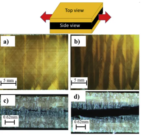
There was not any significant free-edge delamination for the investigated specimens except for the±45 QI/90specimen, hence the observable cracks on the±45 QI/90are due to the free-edge delaminations and fragmentations (See Fig. 12.). Free-edge delamination was observed after the first fragmentations within the carbon laminate. Even if there was significant free-edge delamination, no catastrophic load drop or overall delamination occurred. The reason behind the occurrence of the free-edge is the higher energy release rates at the free-edges of this layup due to the blocked 90 layers compared with the other laminates. Afinite element slice modelling method that was developed in our previ-ous studies[23]was used to show the importance of the stacking sequence on the energy release rates and tofind the interfaces at which free-edge delamination would potentially propagate. The
[image:8.595.98.491.65.298.2]Abaqus Virtual Crack Closure Technique (VCCT) subroutine and 3D 8-noded brick elements (C3D8I) were used to calculate the energy release rates. The stress state does not vary along the length of the specimen for the regions far away from the end tabs. Therefore, a generalised plane strain solution was applied to avoid modelling the full length of a specimen.
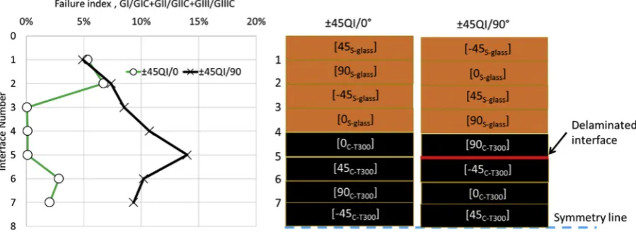
Fig. 13shows the failure index, defined as GI/GIcþGII/GIIcþGIII/ GIIIc, calculated for delamination lengths of 5 mm at a far-field strain of 1% at all interfaces for the ±45QI/0 and ±45QI/þ90
Fig. 11.Pictures from the top surface of the specimens before loading and interrupted tests, appearance of the specimen in different configurations for strain levels close to thefinal
failure.
Fig. 12.Carbon-ply fragmentation for the interrupted±45QI/þ90specimens a) Top
[image:8.595.305.552.459.694.2]layups. Typical values of 0.2, 1.0 and 1.0 N/mm were used for GIc, GIIc and GIIIc, respectively. The assumed strain at which the failure indices are calculated is well below failure, hence the absolute values are relatively low. The failure indices are quite similar at interfaces 1 and 2 in both layups, whereas the failure indices are much larger for the other interfaces in the ±45QI/þ90 layup compared to the ±45QI/0 layup. The failure index reaches its maximum value at interface 5 (around 14%), this interface is crucial for free-edge delamination. This is consistent with the experi-mental observations and the side view picture taken from the ±45QI/þ90layup illustrated inFig. 12c, where free-edge delami-nation initiated at interface 5 after thefirst fragmentations within the carbon laminate.
4. Conclusions
The aim of this work was to generate high performance QI composite laminates that show pseudo-ductility in all thefibres orientations under tensile loading. This aim was successfully ach-ieved by designing, manufacturing and testing novel QI thin-ply carbon/glass hybrid laminates. The laminates were made with orientation-dispersed layups in which non-hybrid multi-direc-tional S-glass/epoxy and T300-carbon/epoxy sub-laminates were put together to build the hybrid laminate. The following conclu-sions are drawn:
1. The investigated QI laminates showed the desired pseudo-ductility in all the fibre directions, with an obvious plateau and without any catastrophic delamination before the final failure. The orientation-dispersed concept successfully sup-pressed free-edge delamination, which was an unwanted damage mode in the previously investigated QI laminates fabricated using the orientation-blocked concept. Pseudo-ductile strains of up to 1.3% were achieved, with strengths up to 504 MPa.
2. Microscopic observation showed carbon ply fragmentations just in the 0 carbon plies with overall fragmentation path angles that are oblique. The angle is affected by the other carbon layers adjacent to the 0carbon layer, and is between the transverse direction and the orientation of the adjacent carbon layers. 3. A significant hybrid effect was observed, with a pseudo-yield
strain corresponding to carbon ply failure of 1.90% for the ±45QI laminates with the 0 carbon plies adjacent to the 0 glass plies, compared with only 1.6% in some of the other ±60QI configurations. The effect was found to be dependent on the
stiffness of the inner plies separating the 0carbon plies and the plies adjacent to the 0 carbon plies. Altering the stacking sequence influences the stiffness of the separator and adjacent plies, therefore, leads to changes in the pseudo-yield strain and final failure stress/strain.
Acknowledgements
This work was funded under the UK Engineering and Physical Sciences Research Council (EPSRC) Programme Grant EP/I02946X/1 on High Performance Ductile Composite Technology in collabora-tion with Imperial College, London. The authors acknowledge Hexcel Corporation for supplying materials for this research. The authors would like to thank Mr Guillermo Idarraga for his help in processing the data. The data necessary to support the conclusions are included in the paper.
References
[1] N.L. Hancox, Fibre Composite Hybrid Materials, Applied Science Publishers Ltd., London, 1981.
[2] J. Summerscales, D. Short, Carbonfibre and glassfibre hybrid reinforced plastics, Composites 9 (1978) 157e166.
[3] D. Short, J. Summerscales, Hybridsea review Part 1. Techniques design and construction, Composites 10 (1979) 215e221.
[4] D. Short, J. Summerscales, Hybridse a review Part 2. Physical properties, Composites 11 (1980) 33e38.
[5] G. Kretsis, A review of the tensile, compressive,flexural and shear properties of hybridfibre-reinforced plastics, Composites 18 (1987) 13e23.
[6] G. Marom, S. Fischer, F.R. Tuler, H.D. Wagner, Hybrid effects in composites: conditions for positive or negative effects versus rule-of-mixtures behaviour, J. Mater Sci. 13 (7) (1978) 1419e1426.
[7] N. Svensson, Manufacturing of thermoplastic composites from commingled yarnsea review, J. Thermoplast. Compos Mater 11 (1) (1998) 22e56. [8] H. Diao, A. Bismarck, P. Robinson, M.R. Wisnom, Pseudo-ductile behaviour of
unidirectional fibre reinforced polyamide-12 composite by intra-tow hy-bridization, in: Proceedings of ECCM 15 Conference. Venice, June, 2012. [9] T. Hayashi, Development of new material properties by hybrid composition.
1st report, Fukugo Zair. Compos. Mater. 1 (1972) 18e20.
[10] T. Hayashi, K. Koyama, A. Yamazaki, M. Kihira, Development of new material properties by hybrid composition. 2nd report, Fukugo Zair. Compos. Mater. 1 (1972) 21e25.
[11] A.R. Bunsell, B. Harris, Hybrid carbon and glassfibre composites, Composites 5 (1974) 157e164.
[12] J. Aveston, J.M. Sillwood, Synergisticfiber strengthening in hybrid composites, J. Mater Sci. 11 (10) (1976) 1877e1883.
[13] P.W. Manders, M.G. Bader, The strength of hybrid glass/carbonfibre com-posites, J. Mater Sci. 16 (1981) 2233e2245.
[14] T. Yokozeki, Y. Aoki, T. Ogasawara, Experimental characterization of strength and damage resistance properties of thin-ply carbonfiber/toughened epoxy laminates, Compos Struct. 82 (2008) 382e389.
[image:9.595.78.528.68.232.2][15] H. Saito, M. Morita, K. Kawabe, et al., Effect of ply-thickness on impact damage morphology in CFRP laminates, J. Reinf. Plast. Compos 30 (2011) 1097e1106. [16] T. Yokozeki, A. Kuroda, A. Yoshimura, T. Ogasawara, T. Aoki, Damage
characterization in thin-ply composite laminates under out-of-plane trans-verse loadings, Compos Struct. 93 (2010) 49e57.
[17] G. Czel, M.R. Wisnom, Demonstration of pseudo-ductility in high performance glass-epoxy composites by hybridisation with thin-ply carbon prepreg, Compos Part A Appl. Sci. Manuf. 52 (2013) 23e30.
[18] M. Jalalvand, G. Czel, M.R. Wisnom, Damage analysis of pseudo-ductile thin-ply UD hybrid compositesea new analytical method, Compos Part A 69 (2015) 83e93.
[19] M. Fotouhi, P. Suwarta, M. Jalalvand, G. Czel, M.R. Wisnom, Detection offibre fracture and ply fragmentation in thin-ply UD carbon/glass hybrid laminates using acoustic emission, Compos. Part A Appl. Sci. Manuf. 86 (2016) 66e76. [20] Y. Swolfs, L. Gorbatikh, I. Verpoest, Fibre hybridisation in polymer composites:
a review, Compos. Part A 67 (2014) 181e200.
[21] M.R. Wisnom, G. Czel, Y. Swolfs, M. Jalalvand, L. Gorbatikh, I. Verpoest, Hybrid effects in thin ply carbon/glass unidirectional laminates: accurate experi-mental determination and prediction, Compos Part A 88 (2016) 131e139.
[22] G. Czel, T. Rev, M. Jalalvand, M. Fotouhi, MR. Wisnom. Demonstration of pseudoductility in quasi-isotropic laminates comprising thin-ply UD carbon/ epoxy hybrid sublaminates, ECCM17 17th European Conference on Composite Materials (Munich, 26e30 June 2016).
[23] M. Jalalvand, M. Fotouhi, G. Czel, MR. Wisnom. Avoiding free edge delami-nation in Quasi-Isotropic pseudo-ductile hybrid laminates e by material dispersion or layer angle dispersion? ECCM17 17th European Conference on Composite Materials (Munich, 26e30 June 2016).
[24] S.R. Hallett, M.R. Wisnom, Numerical investigation of progressive damage and the effect of layup in notched tensile tests, J. Compos Mater 40 (2005) 1229e1245.
[25] T300 Data Sheet - No. CFA-001. n.d. (http://www.toraycfa.com/pdfs/ T300DataSheet.pdf).