Georgia
Institute
of
T
e
chn
010
gy
RICH ELECTRONIC COMPUTER CENTER / (404) 894-3100/ ATLANTA, GEORGIA 30332PROGRAMMERS REFERENCE MANUAL for the
UNIVAC 1108
EXEC 8 EXECUTIVE SYSTEM
PROGRAMMERS REFERENCE MANUAL for the
UNIVAC 1108
EXEC 8 EXECUTIVE SYSTEM
PREFACE
This manual is one of a series of manuals prepared by the Rich Electronic
Computer Center for the benefit of its users. It is primarily concerned with
a description of the Exec 8 Executive System, its control language, and
cer-tain programs that act as an interface between the user and the executive to
perform utility functions.
Scope
The syntax and semantics of programming languages, such as FORTRAN, COBOL,
and ALGOL, are not described here. Additional RECC and UNIVAC manuals provide
information in this area.
Application programs such as GPSS, SIMULA, SIMSCRIPT, and Linear
Program-ming are likewise not described. This is partly due to the long and rapidly
lengthening list of applications programs available.
Although the basic mechanisms by which language processors (compilers)
and application programs are called out are given here, the documentation on
each individual component usually gives more specific information.
Since the demand mode of operation, from a Teletype or similar device,
cannot be divorced from the executive as a whole, there are many references
to demand mode in this manual. However, there are features of the executive
pertaining only to demand mode, and these have been avoided. The RECC
publication, Demand Terminal Users' Manual for the UNIVAC 1108, presents
examples of demand usage and technical information on exclusively demand
features. However, the serious demand user will want to reference this manual
for detailed information on control statements and system processors used in
both batch and demand modes.
Reading Guide
This is a reference manual, not an instructional manual. This means
that it is ordered by subject and not by degree of difficulty or utility.
Due to the volume of information given, it is not practical to read it from
It is suggested that the novice user begin at the back, with the sample deck setups. These will often supply enough information to begin running programs. Also, they will point out frequently used control statements and FURPUR commands. Through the Table of Contents, the user may find additional information on the constructs that interest or confuse him. Certainly,
everyone will read the @RUN, @PWRD, processor call, and @FIN statements.
Sooner or 1ater\ most people will tackle the chapter on I/O specification statements. The @ASG statement often confuses new users, but it is the heart of the Exec 8 file system. Don't try to understand the whole chapter the first few times through. Especially 'avoid F-cyc1es, because they are rarely used.
Glance through the chapter on System Processors, if only to find out what's available. It will expose you to exclusive Exec 8 features.
You'll undoubtedly be forced to look at the appendix on diagnostic messages. Exec 8 messages are often in a coded form, to help minimize com-puter overhead.
If possible, sit down at a Teletype and try some things. It's easier to learn when errors can be corrected interactively and· when files can be dynamically inspected. ~lso, the staff of the computer center is available for help.
The first three chapters contain the lowest density of useful information about the system. However, do read about Program Protection and Program Files. Read the rest at your leisure.
In short, don't read the manual, reference it. It would be quite
impossible to comprehend the information given without frequently interacting with the system. Here's wishing you an enjoyable and productive re1at10nship with the 1100 series executive system, Exec 8.
Changes in the Second Edition
This is the second edition of this manual. The first edition was published on April 1, 1969, prior to the full-time use of Exec 8 at Georgia Tech. Since that time, much knowledge about and experience with Exec 8 have been gained by both our users and the computer center staff. It is hoped
We have attempted to clarify points in the manual that have confused
users in the past. Much of the chapter "I/O Specification Statements" was
expanded and rewritten. Answers to repeatedly asked questions, such as
"How do I make extra copies of my printout?" and "How do I change the
printer margins?" were included. Information regarding the Georgia Tech
configuration was added, including descriptions of all mass storage, magnetic
tape, and symbiont devices.
The sections on FORTRAN, ALGOL, COBOL, and Applications Programs were
removed in the belief that these subjects could be handled better in separate
manuals. The remaining sections were renumbered in a more consistent manner
than before.
Of course, much of the work involved bringing the manual up to date.
The newer features such as batch passwords and saving of catalogued files,
and the revised method for saving tapes had to be documented. Also, several
enhancements such as @LIST, TD8, and @TSTCAT are now described. Features
that were described in the original manual, but are not yet operational, were
deleted in hopes of having everything in the manual work as indicated.
We have attempted to create a correct, complete, and useful manual for
our user community. Your suggestions on how we may reach higher toward that
goal will be greatly appreciated.
Acknowledgment
Most of the material in this manual is reproduced (with appropriate
editing for the Georgia Tech environment) with the kind permission of the
UNIVAC Division of Sperry Rand Corporation from their EXEC 8 Programmer's
1.
2.
TABLE OF CONTENTS
THE EXECUTIVE SYSTEM DESIGN CRITERIA • • • • • 1.1. Operational Capabilities • • • • • . • • • 1.2. Exec Relation to Other System Components • 1.3. Functional Objectives • • • • • . • • 1.4. Range of Executive System Capabilities •
1.4.1. Batch Processing • • • • • • . 1.4.2. Demand Processing
1.4.3. Real-Time Processing • • • • • • • • •
1.5. Program Protection • • • • • • • • .
1.6. Mass Storage Uit1ization Techniques • • • . . • • • 1.7. Program Files • • • • • . . • •
1.7.1. Basic Concept • • • • • • • 1.7.2. Program File Elements
1.7030 Element Name and Version • • • • • . • • • • 1.7.4. Element Versions.
1.7.5. "Cycle" Parameter
BASIC CONCEPTS OF THE UNIVAC 110B EXECUTIVE SYSTEM •
2.1. Definitions.. • • • • • •
2.1.1. 2.1.2. 2.1.3. 2.1.4. 2.1.5. 2.1.6. 2.1.7. 2.1.B. 2.1.9. 2.1.10. 2.1.11. 2.1.~2. 2.1.13. 2.1.14. 2.1.15. 2.1.16. 2.1.17. 201.1B. 2.1.19. 2.1.20. 2.1.21. 2.1.22. 2.1.23. 2.1.24. 2.1.25. 2.1.26.
Acti vity • • • • • • • Activity Registration Batch Processing • Breakpoint • • • . Central Site • • Collection • • .
Communication Device • Demand Processing • • • •
Element • • • • • •
Executive Control Language • Facilities • • • .
File • • • • • • • • Granule
Multi-Programming
Packet • • •• • • • • • Processor Call Statements Program
Program File • • • • • •
Real-Time Processing • •• • • • Re-entrant Coding • . • . . • • •
Remote Site . • • •
Run . • • . . • • Simulated Fastrand Swapping • • • . • System Processor • Task • •• •• • . 2.2. System Conventions
2.2.1. Symbolism \
. .
.
3.
4.
TABLE OF CONTENTS (Cont.)
COMPONENTS OF THE EXECUTIVE SYSTEM • • • • 3.1. Supervisor . . • • . .
3.2. Executive Requests • • • • • 3.3. Symbionts. . • . . . • • • . 3.4. Input-Output Device Handlers 3.5. Operator Communications 3.6. File Control System . • 3.7. Data Handling • • • •
3.8. File Utility Routines . . • . • 3.9. Auxiliary Processors
3.10. Processor Interface Routines 3.11. The Diagnostic System
EXECUTIVE CONTROL LANGUAGE 4.1. Purpose . . . .
4.2. Statements . • . . .
4.3.
4.2.1. General Content 4.2.2. Statement Format
4.2.2.1. Label Field. 4.2.2.2. Command Field 4.2.2.3. Options Field.
4.2.2.4. Specification Field. 4.2.2.5. Leading Blanks
4.2.2.6. Comments Field • • • • . 4.2.3. Continuation Rules . • • • • •
Statement Types • • • . • • • • •• • •
4.3.1. General. • • • • • • . • • • • . Organizational Statements •
4.4.1. The @RUN Statement
4.4.1.1. PRIORITY Subfie1d 4.4.1.2. OPTIONS Subfie1d 4.4.1.3. RUNID Field • • • 4.4.1.4. REFERENCE-NUMBER Field 4.4.1.5. USER-NAME Field. 4.4.1.6. RUN-TIME Field 4.4.1.7. PAGES Subfie1d
4.4.1.8. CARDS Subfie1d • • • • 4.4.1.9. START-TIME Field
4.4.1.10. RUN Restrictions
4.4.1.11. @RUN Statement Examples. 4.4.2. The @FIN Statement
4.4.3. The @MSG Statement • • • • •
4.4.4. The @HDG Statement . • • • • 4.4.4.1. Print-Control Functions. 4.4.5. The @ADD Statement
4.4.6. The @START Statement • • • • • • 4.4.7. The @BRKPT Statement . • • 0 • • •
4.4.7.10 Examples of the @BRKPT Statement 4.4.8. The @SYM Statement • • • • • . . . . • •
4.4.8.1. Use of @SYM with PRINT$ and PUNCH$
4.5.
TABLE OF CONTENTS (Cont.)
4.4.9. The @COL Statement • • • • • •• . • • •
4.4.9.1. 026 Mode . . • . • • • .
4.4.9.2. 029 Mode. . . . • •
4.4.10. The @PWRD Statement . . • • • •
4.4.10.1. Format and Placement of @PWRD Statement 4.4.11. The @ BIN Statement . • . • • • • • • 4.4.12. The @LOG Statement • . . • • • . . . . • •
Input/Output Specification Statements • . • .
4.5.1. General File Information • • • . . • • • • 4.5.1.1. Introduction . . • • . . • . • • 4.5.1.2. Input/Output Peripheral Equipment
4~5.1.2.l. Mass Storage Equipment • .
4.5.1.3. 4.5.1.4. 4.5.1.5. 4.5.1.6. 4.5.1.7. 4.5.1.8.
4.5.1.2.2. Magnetic Tape Equipment Temporary Versus Catalogued Files Notation for Filenames . . . • • . Mass Storage Policy and Procedures Definition of "Assigned" • • •
Methods of Assignment of Files • • • • Unloaded Mass Storage of Files
4.5.1.8.1. Selection of Files to Unload • • • . . .
4.5.1.8.2. Reloading of Unloaded Files 4.5.1.9. Disabled Files • • • • . ' • . • . . • •
4.5.1.9.1. Incomplete Write Disable. 4.5.1.9.2. Destroyed Disable
4.5.1.9.3. Bad Backup Disable
4.5.2. The Mass Storage @ASG Statement • • • . . • • • • 4.5.2.1. The 'OPTIONS'I Subfield . .
4.5.3.
4.5.4. 4.5.5.
4.5.2.2. The 'FILENAME' Field. • • • •
4.5.2.3. 4.5.2.4. 4.5.2.5.
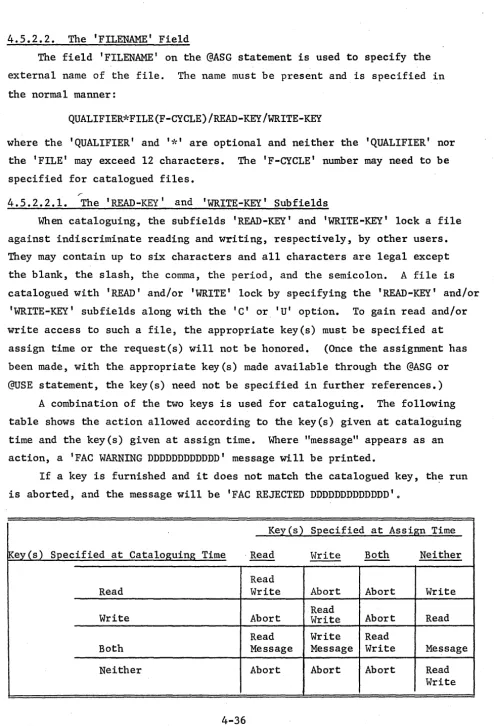
4.5.2.2.1. The 'READ-KEY' and 'WRITE-KEY' Subfields
The Facilities Field • • . •• • • Exclusive Use and Facility Handling Examples of the Mass Storage @ASG Statement • • . • . •
4.5.2.6. Diagnostic Messages The Magnetic Tape @ASG Statement •
4.5.3.1. The' OPTIONS' Subfie1d • • . . • • • . 4.5.3.2. The 'FILENAME' Field • . • • • • .
4.5.3.3. The Facilities Field. . • . .
4.5.3.4. The Reel Field. • . • • . • • • . 4.5.3.4.1. Using Scratch Tapes
4.5.3.4.2. Saving Tapes • . . . 4.5.3.4.3. Using Tapes Previously
Saved
4.5.3.5. Examples of the Magnetic Tape @ASG Statement
The @MODE Statement . . • . • • The @CAT Statement . • . • . . • • •
5.
4.6.
4.7.
4.8.
4.9.
TABLE OF CONTENTS (Cont.)
4.5.6. The @FREE Statement. • . •• • • • • • • • . 4.5.7. The @USE Statement . • • • • . • . . . • • •
4.5.7.1. External, Internal, and Attached Names 4.5.7.2. Format of the @USE Statement . . . • . 4.5.7.3. Use of the @USE Statement • . • . . 4.5.7.4. Examples of the @USE Statement
4.5.7.5. File Name Uniqueness Within a Run
4.5.8. The @QUAL Statement • . • • • . • • . • • • . • . Processor Call Statements . . • . . • . • • • .
4.6.1. Notation for Program File Elements • . • • • 4.6.2. Statement Format for Language Processors
4.6.3. Format of Correction Lines • • • • •
4.6.4. The System Program Files, SYS$*RLIB$, SYS$*LIB$, and TPF$ • . • • . . • • • • •
Program Execution Statements . • • •
4.7.1. The @MAP Statement • • • • .
4.7.2. The @XQT Statement . • . . . . • .
4.7.3. The @EOF Statement • • • • •
4.7.4. The @PMD Statement . • • • • • • • . . • • . Conditional Statements • • • • . • • • • . . • • • 4.8.1. Purpose of Conditional Statements
4.8.2. Statement Labels
4.8.3. The @LABEL Statement • • • • .
4.8.4. The "CONDITION" Word . • • • • • . • . • • 4.8.5. The @SETC Statement.
4.8.6. The @JUMP Statement • • . • . . • . • • 4.8.7. The @TEST Statement . . . • •
Statement Syntax Error Diagnostics
FILE UTILITY ROUTINES (FURPUR) 5.1. General • • . • . .
5.2. Statement Format . • . • • • • • • . • . • •
5.2.1. Contents of Specification Fields 5.2.2. File Assignments
5.2.3. Options Field. 5.3. Shorthand Notation 5.4. FURPUR Statements
5.4.1. @COPY • .
5.4.1.1. Formatting the @COPY Statement . • . • 5.4.1.2. Examples of the @COPY Statement.
5 .4. 2. @COPOUT. • . • . . • • • • • • . • • . • • • • . 5.4.2.1. Formatting the @COPOUT Statement
5.4.2.2. Examples of the @COPOUT Statement • • . 5.4.3. @COPIN • . • • • • • • • • • . . . • • • • •
5.4.3.1. Formatting the @COPIN Statement •• 5.4.3.2. Examples of the @COPIN Statement 5 • 4 • 4 . @DELETE. • • • . • . • • • • • . . . . • • .
5.4.4.1. Formatting the @DELETE Statement
6.
5.5.
TABLE OF CONTENTS (Cont.)
5.4.5. @PRT. • • • • • • • • • . • • . . . . • • • • .
5.4.5.1. Formatting the @PRT Statement • • • • 5.4.5.2. Examples of the @PRT Statement.
5.4.5.3. Notes on @PRT,T • • • • • • • • • 5 • 4 • 6 • @PCH. • • • • • • • . • • • • • . . . • • •
5.4.6.1. Formatting the @PCH Statement • • • • 5.4.6.2. Examples of the @PCH Statement.
5 • 4. 7 • @CHG. • • • • • • • . • • • • • • • • • 5.4.7.1. Examples of the @CHG Statement. 5.4.8. @PACK
5 • 4. 9 • @PREP 5.4.10. @ERS • 5.4.11. @REWIND 5.4.12. @MARK 5.4.13. @CLOSE • . 5.4.14. @MOVE • • • • 5. 4. 15. @FIND
5.4.16. @CYCLE • • • • • • .
5.4.16.1. Formatting the @CYCLE Statement 5.4.16.2. Examples of the @CYCLE Statement • 5.4.17. @ENABLE
Mu1tiree1 Files
SYSTEM PROCESSORS • • • • .
6.1. The COLLECTOR (@MAP Processor) •
6.1.1. General • • • • • • . . • • • • 6.1.2. Executive Control Statements.
6.1.2.1. The @MAP Control Statement • • . 6.1.2.2. .The @XQT Control Statement •
6.1.3. COLLECTOR Control Statements. • • • •
6.1.4. 6.1.5. 6.1.6.
6.1.3.1. General . • • • • • . • • • • • 6.1.3.2. The IN Statement . . • • • 6.1.3.3. The NOT Statement
6.1.3.4. The LIB Statement 6.1.3.5. The SEG Statement 6.1.3.6. The DSEG Statement
6.1.3.7. The RSEG Statement • • • • 6.1.3.8. The DEF Statement
6.1.3.9. The REF Statement
6.1.3.10. The ENT Statement •• • • . • • • 6.1.3.11. The EQU Statement
6.1.3.12. The CLASS Statement 6.1.3.13. The COR Statement
6.1.3.14. The SNAP Statement • . . • • • • . 6.1.3.15. The END Statement
Functional Aspects • • • . • • • • • • COLLECTOR Defined Symbols • • • • • Program Segmentation and Loading •
7.
8.
9.
TABLE OF CONTENTS (Cont.)
6.2. The Procedure Definition (@PDP) Processor •
6.3. 6.4. 6.5. 6.6. 6.7.
6.2.1. General • . . . . 6.2.2. FORTRAN Procedure 6.2.3. COBOL Procedure TEXT EDITOR (@ED)
The @ELT Processor The @DATA Processor
The @END Statement
.
· .
The @LF Processor· ·
·
·
· ·
·
6.7.1. The @LF Processor Call Statement 6.7.2. Functional Aspects of @LF
·
6.7.3. Examples of the @LF Statement 6.8. The LIST ProcessOr. · .
. .
·
·
6.8.1. The Processor Call Card
·
·
·
6.8.2. Notes on the Printed Output·
6.8.2.1. Symbolic Elements·
6.8.2.2. Relocatable Elements 6.8.2.3. Absolute Elements 6.9. The @TSTCAT Processor·
THE DIAGNOSTIC SYSTEM . • . • • . . 7.1. The @PMD Statement
7 . 1 • 1 . Gener a 1 . . 7.1.2. Options . . . .
7.1.2.1. General Options.
·
·
·
. ·
. ·
·
·
·
·
·
·
·
·
·
. .
·
·
·
·
· ·
·
· ·
·
· ·
·
· .
·
·
·
·
·
· ·
7.1.2.2. Special Options . • . . .
7.1.2.3. Options Used with Special Options. 7.1.2.4. The 'Blank' Option
7.1.3. Examples
UTILITY ROUTINES . • • • .
8.1. Convers ion Aids . . • . . . • . .
8.1.1. UNIVAC 1108 (EXEC II) to UNIVAC 1108 (EXEC 8) . . 8.1.2. LIFT (FORTRAN II to FORTRAN V Translator) . • 8.2. The TD8 Routine • • . • • • . . • • .
8.2.1. Execution. • • • .
8.2.2. Data Card. . • • • • • • • . .
8.2.3. Results . . . • • . .
8.2.4. Example . . . • . .
SAMPLE DECK SETUPS • • • .
9.1. Compile Only . . . . . • • • .
9.2. Compile and Execute. . • • • • •
9.3. Compile and Execute Main ,Program With Two Subroutines 9.4. Compile and Catalogue Original Program • • • • • 9.5. Test Corrections to Existing Program and Execute 9.6. Update Existing Program and Execute • . • • • . •
9.7. Execute Existing Programs Using Catalogued Data Files • .
9.8. 9.9. 9.10. 9.11. 9.12. 9.13.
TABLE OF CONTENTS (Cant.)
Compile Program and Store It on Tape • • Execute Program Stored on Tape . . .
Create Multiple Print Output Copies • • . . Divert Print Output to Tape
Print Output Previously Diverted to Tape • • . Run Two Runs in Sequence . • • •
APPEND IX A. CHARACTER CODES FOR THE U 1108
APPENDIX B. DIAGNOSTIC MESSAGES
APPENDIX C. STANDARD TAPE TRANSLATION (BCD-FIELDATA) .
Page
9-7 9-8 9-8 9-9 9-10 9-10
A-I
B-1
1. THE EXECUTIVE SYSTEM DESIGN CRITERIA
1.1. Operational Capabilities
To take maximum advantage of the speed and hardware capabilities of the
UNIVAC 1108 computer and to make effective use of a given hardware
configu-ration, a complex internal operating environment has been created.
This environment allows for the concurrent operation of many programs;
it allows the system to react immediately to the inquiries, requests, and
demands of many different users at local and remote stations; it allows for
the stringent demands of real-time applications; it is able to store, file,
retrieve and protect large blocks of data; and it makes optimum use of all
available hardware facilities, while minimizing job turnaround time.
Only through central control of all activities of the UNIVAC 1108 can
this environment of the combined hardwa~e and software systems be fully established and maintained to satisfy the requirements of all applications.
This responsibility for efficient, flexible, centralized control is borne
by the Exec. The Exec controls and coordinates the functions of this
complex internal environment and, by presenting ,a relatively simple
inter-face to the programmer, allows him to use the system easily while relieving
him of concern for the internal interaction between his program and other
co-existent programs.
1.2. Exec Relation to Other System Components
The UNIVAC 1108 Executive System includes a complete set of
source-language processors including FORTRAN V, COBOL, and ALGOL. The operation
of all of these processors is controlled by the Exec for the user of the
system. By the Executive's assumption of the responsibility for: 1) calling
in processors as required, 2) providing inputs to the processors, 3) storage
and maintenance of the outputs of the processors, and
4)
the integration ofactivities involving sequences of processor calls, a processor's operation
can be confined to the actual processing involved in a single activity.
The Executive System will take care of all other functions.
Other components of the 1108 Software System such as SORT/MERGE, APT,
PERT/COST, and LP (LINEAR PROGRAMMING) interface with the Executive System
1.3. Functional Objectives
The primary objectives in the design of the 1108 Executive System are as follows:
(1) To optimize machine facilities usage, and at the same time optimize interaction for all users by the use of mu1ti-programming/mu1ti-processing techniques.
(2) To make available to remote users the complete facilities of the 1108 System.
(3) To provide an Executive Control Language whose structure will
allow simple programs to have a simple means of expressing their requirements. (4) To provide the flexibility to express a complex environment for complex programs.
(5) To provide a broad and easily-used spectrum of program construction, manipulation, and checkout aids, including the permanent storage of program elements on random-access devices.
(6) To provide for tasks to be executed in either batch, demand, or real-time mode.
(7) To provide a simple and flexible means of complete software system generation and maintenance at the individual installation.
(8) To provide system invulnerability to programming error and, as far as is reasonable, hardware errors.
(9) To provide the simplest possible operational characteristics consis-tent with full utilization of the capabilities.
1.4. Range of Executive System Capabilities
The technical capabilities of the UNIVAC 1108 Executive System s~an a broad spectrum of data processing activities. Its design is such that no penalties of inefficiency are imposed upon one of these activities by the support provided for the other activities.
1.4.1. Batch Processing
inputs,through the Exec's use and control of efficient multi-programming
techniques, may undergo what is essentially simultaneous input, processing,
and output. Thus, in a demanding environment, the full capabilities of
the 1108 can be utilized efficiently.
1.4.2. Demand Processing
The Exec provides simultaneous use of the 1108 by many users at remote
consoles to optimize the user/system interaction rates. Each user shares
control of the computational facilities and has the full capability of the
1108 configuration at his disposal.
The demand mode of processing is initiated and controlled by the
Executive Control Language. Commands are input via the user's remote console
on a conversational basis; that is, an immediate system response will be
apparent.
Provisions are made for: (1) Dialed communication connection in
addition to leased lines and remote consoles on site; (2) paper tape input
allowing pretyped command programs with data for high efficiency communication
transmission; (3) user communication with the computer operator and the
Exec itself.
1.4.3. Real-Time Processing
A basic responsibility of the Exec is to assist real-time communications
(RT/C) programs with Exec functions provided to allow RT/e programs to
appropriately influence the Exec and the multi-program background. No
attempt is made to generalize the control required in each RT/C program in
recognition of the specific tailoring of a RT/C program to both the
hard-ware configuration and the process controlled.
Exec is sensitive to the nature of RT/C processing and provides
appropriate mechanisms for: lockout protection from simultaneous record
access during program execution; priority sensitivity; protection to RT/C
programs from interference because of peripheral access of background
programs (search functions, etc.)
Interface with non-standard peripherals can be at the hardware level
(I/O commands and interrupts). Exec awareness of individual transmission
1.5. Program Protection
The multiprogramming capabilities of the Executive System imply that
many unrelated programs may be residing in main storage at the same time.
Such programs may be real-time runs, production runs, classified runs, or
simple debugging runs. Infringement of privacy in such a mixture is
highly probable especially in cases where debugging runs are executing.
The knowledge or ignorance of an invasion may range from little or no
con-cern for some runs to great concon-cern for classified or realtime runs.
To combat this invasion, intentional or unintentional, the Executive
System has unique features that automatically guarantee absolute protection
for each program. The protection guards against two forms of invasion,
direct and indirect.
Direct protection safeguards all programs in main storage from an
active program that may attempt to read, write, or jump into another program
area. This safeguard is effected by "Locking Out" any area of main storage
that is not assigned to the presently active program or, in effect,
"Locking In" the active program. Any attempt to perform any of the above
functions is immediately reported to· the Executive Sys.tem, which normally
terminates the program with an IGDM (guard mode violation) message.
Indirect protection is realized by reserving certain control functions
for the exclusive use of the Executive System. These functions are of the
type that could cause a system malfunction and, in turn, a program
malfunc-tion if erroneously used. The Executive System will prohibit the use of
these functions.
In both forms of protection, the Executive System is, in reality,
guaranteeing its own safety from abuses that may prove catastrophic to the
system.
1.6. Mass Storage Utilization Techniques
The UNIVAC 1108 Executive System is designed to provide installations
with an effective and efficient utilization of the mass storage devices
available with the 1108. The result is an ability to relieve operators
and programmers of responsibilities in· maintaining and physically handling
cards, magnetic tapes, etc., thus eliminating many of the errors which
previously accompanied the use of large-scale software systems. At the
Provisions are made for the maintenance of permanent data files and
program files on the mass storage devices, with full facilities for
modification and manipulation of these files. Security measures are invoked
by the Executive System to insure that files are not subjected to unauthorized
use. As unused mass storage space approaches exhaustion, provisions are
also made within the Executive System for automatic relocation of files of
low usage-frequency to magnetic tape. When the use of files relocated in
such a manner is requested, they are retrieved and restored, under control
of the Executive System, with no inconvenience to the user. For the most
part, dynamic assignment of mass storage space is available to the user via
the Executive System. To facilitate efficient utilization of available
facilities, the user is also able to return portions of mass storage to
general use as he finishes with them.
1.7. Program Files
1.7.1. Basic Concept
The concept of a program file is fundamental to an understanding of
the 1108 software system. A program file is essentially a named set of
elements. The file name is the prime identifier for the set of elements.
To identify and locate the elements within a program file, a Table of
Contents is created, and maintained within the program file by the system.
1.7.2. Program File Elements
Within the Table of Contents, each element within the program file is
uniquely identified by the following four parameters:
(1) Element type
(2) Element name
(3) Element version
(4) Element cycle
Also included are various parameters such as the date of element
creation and the current relative location of the element on mass storage.
The elements contained within a program file are of the following
three types:
(1) Source language, or more generally, variable length data images
Typical source-language elements are the following:
(1) FORTRAN source program (2) COBOL source program (3) COLLECTOR source element
Any of these elements may be introduced into a program file or manipulated with a file by the use of the appropriate processor (FORTRAN, COBOL, etc.) or by certain utility routines.
The following elements may be thought of as being special-case source-language elements:
(1) COBOL procedure elements (2) FORTRAN proce~ure elements
These elements are available to the language processors essentially as source-language library elements. Special elements are required by the system to facilitate the retrieval of source language library elements at compilation time. However, these elements are created and maintained by the system and require no concern on the part of the user.
In addition to the above source elements, sets of executive control-statements may be entered as source elements. These elements may be called by the @START or @ADD statements.
Relocatable elements are the binary output of the processors such as FORTRAN, COBOL, ALGOL, and one special use of the COLLECTOR. Absolute elements are placed in a program file by the COLLECTOR.
1.7.3. Element Name and Version
Each element within a program file is given a name specified by the user. This name is referred to simply as the element name. To distinguish between elements of the same name and type, a user may specify a subname for an element, and this subname is called the element version.
1.7.4. Element Versions
Relocatable elements may be further classified by specifying a class
designation which is applied to the version name. The purpose of this
classification is the selection of elements based on parameters suited for
the particular allocation to be made. Letters within the version names of
elements are given meaning by the programmer which can then be used to
select a proper class or classes according to the need. Each required
element need not be named, but the proper element will be selected by
elimination.
1.7.5. "Cycle" Parameter
For differentiation among symbolic elements, an integer parameter
called "cycle" is associated with each element. This allows several "copies"
of the same version of an element to be retained within a program file.
Each item (image) of a symbolic element has a cycle number indicating to
which cycle it belongs, and, if deleted, a delete-cycle number to indicate
in which cycle this item was deleted. When a symbolic element is updated,
the update items are inserted where they belong in the element and given
a cycle number one greater than the last cycle of the element. Any previous
cycle items that have been deleted by this update are marked so. The user
may make references by cycle number. This gives the same effect as though
several different copies of the element were maintained. The user may
set the number of update cycles to be retained at any level he desires;
however, he need set that number if he desires to change it from the
stan-dard system assumption. The standard value is five (5).
In specifying a symbolic element for compilation, the user may reference
a specific update from a sequence of retained updates by specifying the
proper update cycle number as part of the executive control statement calling
for the compiler. In compilation, the update entry will be combined with
the element in its complete state, thereby creating a complete element as
of that cycle.
As soon as the number of updates retained for an element exceeds the
specified maximum, the update of the lowest cycle number (the original,
complete element) is combined with the update next lowest in cycle number;
in effect, the oldest entry is discarded, and the next oldest, in its
This technique of handling symbolic elements offers two distinct advantages:
(1) The user is allowed to keep many differing copies of the same element in a program file while requiring little additional storage over that needed for a single copy.
2. BASIC CONCEPTS OF THE UNIVAC 1108 EXECUTIVE SYSTEM
2.1. Definitions
Certain terms are referred to in this manual with the assumption that
the reader is acquainted with their meaning. The following definitions
are for the convenience of the reader.
2.1.1. Activity
A division of a program which may be executed independent of other
portions of the program. It is usually considered part of a task.
2.1.2. Activity Registration
The act of registering with the Executive System an activity which
can be executed asynchronously with other parts of a program (forking).
2.1.3. Batch Processing
A mode of operation where several runs are grouped prior to processing.
Transition from run to run is effected by the Executive System.
2.1.4. Breakpoint
The division of symbiont defined files. Allows those portions of the
file to be queued independently of run completion. Maximum use of available
printers and punches is achieved in this manner.
2.1.5. Central Site
The 1108 computer and its attached peripheral equipment.
2.1.6. Collection
The process by which elements of a program are collected by satisfying
the external symbols of the initial element and all referenced elements.
The resulting structure defines a program to be allocated and executed.
2.1.7. Communication Device
An input or output device which operates in a real-time mode. The
central processing unit must be prepared to receive input at any time or
the information may be lost.
2.1.8. Demand Processing
The manner of processing in which the Executive System or a processor
spontaneously reacts to the inputs from a remote inquiry terminal which is
2.1.9. Element
The basic component of a program file usually defined and manipulated as a unit. The form of an element is dependent upon the program using it.
2.1.10. Executive Control Language
Specifically formatted input information which is used to direct the activity of the Executive System.
2.1.11. Facilities
The peripheral units, main storage, tape drives, drum storage, etc.
2.1.12. File
An organized collection of data stored in such a manner so as to facilitate the retrieval of each individual datum.
2.1.13. Granule
The incremental size in which a storage unit is assignable.
2.1014. Multi-Programming
The concurrent execution of several programs which occupy main storage. This is accomplished by sharing the attentions of the central processor.
2.1.15. Packet
A contiguous set of words which contain information describing an input/output operation to be performed.
2.1.16. Processor Call Statements
Specifically formatted input information which is used to direct the activity of a sy~tem processor. A subset of the Executive Control Language. 2.1.17. Program
A collection of instructions, execution of which results in performance of one or more logical functions. A program is the subdivision of the
executable aspects of a run.
2.1.18. Program File
2.1.19. Real-Time Processing
An operating environment in which the response to an external stimulus
is sufficiently fast to achieve a desired objective. Depending upon the
application, the response time may vary from seconds to microseconds.
Generally, real-time processing is under the influence of asynchronous
inputs from one or more devices.
2.1.20. Re-entrant Coding
A set of instructions coded in such a manner that they may logically
perform the same task on different data sets simultaneously.
2.1.21. Remote Site
A communications terminal which is capable of sending information to
and receiving information from the central processor via some common carrier
or transmission scheme.
2.1.22. Run
A run is the standard unit in which work is entered into the operating
systemo This consists of a run command followed by one or more control
commands which causes the ordered execution of processors and~or worker
programs.
2.1.23. Simulated Fastrand
Drum simulation of Fastrand which allows execution of a program with
files designed for Fastrand allocation allocated to the section of the
"Flying Head" drum storage designated as simulated Fastrand.
2.1.24. Swapping
The process of storing low priority or suspended programs on secondary
storage in order to allow space to retrieve another program into primary
storage for execution.
2.1.25. System Processor
A program which performs specialized functions under the control of
the Executive System.
2.1.26. Task
A logical step in the processing of a run. For example, execution of
2.2. System Conventions 2.2.1. Symbolism
1. When it is necessary to indicate particular bits in a word, they are numbered from right to left,
35
o
except in the case of the FORTRAN FLD statement where they are numbered from left to right.
2. When parts of words are referenced the following symbols are used:
35 20 29 24 23 18 17 12 11 6 5
o·
Sl S2 S3 54 S5 S6
35 24 23 12 11 0
Tl T2 T3
35 18 17 0
HI H2
3. COMPONENTS OF THE EXECUTIVE SYSTEM
The UNIVAC 1108 ~ecutive System is composed of many different routines, each of which performs a specific function. These routines are organized
into several separate groups which are the basis of discussion in subsequent
sections of this manual. For introductury purposes, a brief description of
each component group follows.
3.1. Supervisor
The supervisor controls the sequencing, setup, and execution of all
runs. Among those routines included within the supervisor are the scheduling
routines, interrupt processing routines, timing routines, and accounting
routines.
3.2. Executive Requests
Executive requests are entrances into the Executive System which provide
functions for a user program. Depending on the function, it may be performed
asynchronously, synchronously, or immediately. If it is not an immediate
request, a queue is maintained.
3.3. Symbionts
Symbionts provide the interface between the primary unit record
equip-ment and the user program. These routines are referenced by using executive
requests for input and output. Input and output are buffered on the mass
storage devices.
3.40
Input-Output Device HandlersThe input-output handlers are responsible for 'controlling the activities
of all I/O channels and peripheral equipment attached to the UNIVAC 1108.
These device handlers provide the user with a full capability of peripheral
device operations.
3.5. Operator Communications
The communications section of the Executive System handles all
communi-cations between the operator and the operating programs. This communication
takes place via the computer keyboard and on-line printer on the console
channel. Neither the keyboard nor the console printer can be assigned to
3.6. File Control System
The file supervisor controls the creation and maintenance of all program
and data files. It also maintains an up-to-date master directory of all
files catalogued in the system-and the availability of all mass storage.
3.7. Data Handling
The data handling routines are designed to process a wide variety of
file formats using a general technique.
Files may be processed at the item or block levels with general disregard
for the physical characteristics of the I/O device assigned. Data are
presented or accepted, randomly or sequentially, on request of the user thereby
providing complete operational flexibility for efficient file manipulation.
3.8. File Utility Routines
To aid the user in the manipulation of program and data files, a set
of file utility routines is provided by the Executive System. These routines
perform a variety of functions for sy'stem and user data file maintenance.
3.9. Auxiliary Processors
A set of auxiliary processors is included in the executive system.
These processors complement the source language processors such as FORTRAN.
This set of processors includes the COLLECTOR for linking re1ocatab1e
sub-programs, and the PROCEDURE DEFINITION PROCESSOR for inserting and modifying
COBOL or FORTRAN procedure definitions in a program-file.
3.10. Processor, Interface Routines
The processor interface routines provide a simple, standard interface
for all processors within the system. Complete facilities are provided for
the input of source-language statements and the output of the resulting
re1ocatab1e binary code.
3.11. The Diagnostic System
A comprehensive diagnostic system is available within the 1108 Executive
System to aid the checkout of user programs. Commands are available which
can trigger snapshot dumps at the time of compilation or collection of a
user routine. Post-mortem dumps are also available through an Executive
4. EXECUTIVE CONTROL LANGUAGE
4.1. Purpose
Control of the operating environment on the UNIVAC 1108 is accomplished
through a set of control statements. These statements direct the executive
in scheduling, assignment of facilities, and in the disposition of program
and data files. The language is designed in a compact and des~riptive manner to facilitate use and yet provide all of the features and functions of a
modern Executive System.
4.2. Statements
4.2.1. General Content
The basic format of the Executive Control Statements is quite simple
and is amenable to a large number of input devices. Statements are not
restricted to a card-image format; hence, they may be of variable lengths.
Each statement consists of a recognition character in column one, followed
by a command which categorizes the statement, followed by a variable number
of specifications fields, and concluded by a comments field. The recognition
character is a master space (@), which is a multiple (7-8) card punch or
its equivalent for other types of input devices. The end of a statement is
signified by the end of a card for card-image input, or by a carriage
return or its equivalent for other types of input devices.
Executive Control Statements are always logged in a batch run's print
file. If a control statement is in error, the diagnostic is printed
immediately folloWing the statement.
4.2.2. Statement Format
The general format of an Executive Control Statement is:
@LABEL:COMMAND, OPTIONS SPEC1, SPEC2, ••• ,SPECN COMMENT
The following gives a description of each of the "fields" of the
Executive Control Statement as well as format and continuation rules.
4.2.2.1. Label Field
The label field need not appear but may be used to name a control
state-ment. The label is limited to six characters from the alphanumeric set
(A ••• Z, 0 .•• 9), the first of which must be an alphabetic. If a label is
4.2.2.2.
Command FieldThe command field must always be specified as it determines the state-ment's basic operation. The command is limited to six characters from the alphanumeric set (A ••• Z, 0 ••• 9), the first of which must be alphabetic. For certain control statements, the options field, which is an appendage to the command field, is recognized. When the options field is specified, the command field terminator is the comma (,). However, if an options field is not specified, blank ( ) is the command field terminator.
4.2.2.3.
Options FieldThe options field provides the user with the ability to specify certain options, in the form of unsequenced alphabetic characters, to the particular processor addressed in the command field or to a specific program as it is executed. On some control statements the options field can be broken into subfields, each of which is separated by a slash
(I).
A blank character or a series of blank characters separates the command or options field from the specifications fields.402.2.4.
Specifications FieldsThe specifications fields of an Executive Control Statement are separated by commas and are specified by the user as dictated by his requirements.
The content of each specification field, the number of specification fields, and whether each is required or optional, varies with the command selected. Specification fields, in turn, may contain subfields that are separated by a slash
(I).
For the most part, these subfields are optional within a field. Thus, it is possible to specify parts of a field without specifying the entire field.In many cases, the specifications on a control statement will be a file name or element name. In the remainder of this manual, the following con-ventions apply (where brackets enclose optional fields):
FILENAME is used to indicate
[[QUALIFIER]*]FILE[(F-CYCLE)][/[READ-KEY][/WRITE-KEY]]
ELTNAME is used to indicate
Qualifier, file, element and version names are 1-12 alphanumeric
characters ('$' and '-' are also allowed). Keys have 1-6 characters from
the entire Fie1data character set, excluding only space, comma, slash,
period, and semicolon. F-cycles are numbered upward from 1; element cycles
are numbered upward from O.
When the qualifier is omitted, the USER-NAME from the @RUN control
statement is used, except in the special case where a leading asterisk
appears before the filename and a qualifier has been previously furnished
on a @QUAL statement. When the F-cycle or element-cycle is omitted, the
most recently created cycle is used.
When the filename portion of an e1tname is omitted, the system usually
assumes an implicit reference to the run's temporary program file, TPF$.
TPF$ is automatically assigned to every run by the system.
Although the distinction between filenames and element names is often
evident from the context, there are many cases where. a period must follow
a filename, or it will not be accepted, or wrongly treated as an element
name. In such cases, 'FILENAMEo-or-ELTNAME' will be used. A period may
always follow a filename, except on a @BRKPTstat·ement.
4.2.2.5. Leading Blanks
Leading blanks are allowable following the recognition character (@),
the colon (:) if a label is specified, the field separator
C,),
and thesubfield separator
C/).
A blank in any other position acts as the separatorsignifying the start of the specification fields or comments field. An
empty field or subfield is one that contains no characters or one or more
blank characters. When all remaining fields or subfields are empty, they
may be omitted.
4.2.2.6. Comments Field
At least one blank character must precede the comment field. The
com-ment itself may contain any character except the semicolon (;), the
contin-uation character. The comment field is ended by end-of-card or its
equivalent for other input devices. The comment field is never required.
If specifications fields are omitted, the comment field must begin with a
period
C.)
followed by a blank. This is also true when the content of a@MSG statement). The @XQT statement is an example of a statement where
specifications are possible but may be omitted.
Note: The above paragraph has described the comment field separator as
follows:
@ control card ~.~ comments
4.2.3. Continuation Rules
In certain situations, a statement may require more than one line or
card. In such cases, coding of a semicolon (;) indicates continuation on
the next card or line. A statement may be split at any point, after the
options field, where a leading space is allowable or within the comment
field. It is treated logically as a space. Continuation on the next line
can begin in any column, with one exception: a master space character
(@)
should not be·placed in column one on a continuation line.
4.3. Statement Types
4.3.1. General
The 1108 Executive System recognizes five types of control statements:
(1) Organizational statements;
(2) input/output specifications statements;
(3) processor call statements;
(4) program execution statements; and
(5) conditional statements.
Each statement is discussed individually in succeeding paragraphs. The
Statement Type Organizational Statements Input/Output Specification Statements
SUMMARY OF EXECUTIVE CONTROL STATEMENTS
~'.
"
~~
;'(
Command
,';: @RUN
*;'(i'( ,';:i~ ;':i'( @FIN @MSG @HDG @ADD @START @SYM @COL @PWRD @ BIN @LOG @ASG @MODE @CAT @FREE @USE @QUAL Usage
Appears at the beginning of each run. Provides accounting, scheduling, and ID information.
Appears at the end of each run.
Places a message on the central-site con-sole typewriter.
Used to place a heading line on print output.
Used to dynamically expand the run stream.
Used to schedule the execution of an independent run.
Used to schedule non-standard symbiont action.
Used to specify form of input, e.g., key-punch code.
Used to specify the user's batch password.
Used to specify the bin number for returning output.
Used to enter text into the system log.
Used to assign a particular input/output device or mass storage file to a run. There are two types of €ASG statements; mass storage and tape. Also used to catalogue Mass Storage files.
Used to change the mode settings (density, parity, etc.) of a tape file.
Catalogues Fastrand files.
Used to deassign a file and its input/ output device or mass storage area.
Used to set up a correspondence between internal and external file names.
Used to define a standard file name qualifier.
SUMMARY OF EXECUTIVE CONTROL STATEMENTS (Continued)
Statement Type
Processor Call Statements
Conditional Statements
Command
@PROCESSOR NAME
@MAP
@XQT
~'( @EOF
@PMD
@LABEL:
@SETC
@JUMP
@TEST
Usage
Used to execute a processor. @COB for COBOL compiler, @FOR for FORTRAN, @ALG for ALGOL, etc.
Used to call the COLLECTOR and prepare an absolute element.
Used to initiate the execution of a program.
Used to separate data within the control stream.
Used to take edited post-mortem dumps of the program just executed.
Used to attach a label to an existing control statement.
Places a value in the 'condition' word.
Used to branch control within the control stream.
Used to test the 'condition' word in'the course of deciding the effective control stream.
4.4. Organizational Statements
4.4.1. The @RUN Statement
The @RUN statement must be the first statement of each run. Its purpose
is to identify the run and to furnish parameters necessary for scheduling
and accounting purposes. The format of the @RUN statement is:
@RUN,PRIORITY/OPTIONS RUNID,REFERENCE-NUMBER,USER-NAME,RUN-TIME,PAGES/CARDS,START-~IME
On the @RUN statement the normal options field is divided into two
sub-fields separated by a slash (/). The first subfie1d specifies the 'PRIORITY'
of the run and the second specifies the 'RUN-OPTIONS.'
The 'RUNID', 'REFERENCE-NUMBER', and USER-NAME' fields are the only
specification fields that need to be specified by the user. For demand runs,
the 'START-TIME' field is not honored.
4.4.1.1. PRIORITY Subfie1d
The priority subfie1d contains an alphabetic character. At system load
time, the following info:mation is specified for each 'REFERENCE-NUMBER' and
'USER-NAME': (1) the highest priority letter allowed for this
'REFERENCE-NUMBER' and 'USER-NAME'
@RUN statement.
(2) priority to use if none is specified on the
The highest priority allowed and the assumed priority are the same for
each 'REFERENCE-NUMBER' and 'USER-NAME'. If the priority on the @RUN
state-ment is higher than allowed, the run is terminated immediately. If the
priority subfie1d is left blank, the priority character is chosen as specified
in the 'REFERENCE-NUMBER' and 'USER-NAME' file entry.
4.4.1.2. OPTIONS Subfie1d
The run 'OPTIONS' subfie1d may be used to place certain constraints on
the run. This field is never required and when left blank, normal system
action occurs. The available options are:
N disallow all postmortem dumps. Specification of this option for runs containing no @PMD statements saves the overhead of dumping core to the diagnostic file at termination of every user program.
If neither N nor Y options are specified, @PMD's will be allowed of
all programs except system processors (FOR, ALG, COB, MAP, FURFUR, etc.).
X Do not automatically reschedule run if it is active during a system failure. This option should be specified if rerunning a partially completed job might destroy data. Appropriate @MSG statements to the operator should also be included in the deck.
S Sequenced runs. If two or more runs must be run in sequence (i.e., a run must finish before the next run can be started), the S option should be used on all run statements except the first. A null bin card mus·t separate the run decks. See Sample Deck Setups for an example of sequenced runs.
4.4.1.3. RUNID Field
The 'RUNID' (identification) field must be specified to identify the
run to the system. This field is limited to a maximum of six characters
from the alphanumeric set (A •.. Z, 0 ••• 9).
If the system finds that a run being submitted has the same runid as
a previous run that has not finished execution, the executive will assign
a unique runid to the run, notify the operator (and the. user, if demand)
of the change, and continue processing the run. The new ID is used for all
operator-executive communications concerning the run. Normally, the new
ID is established by adding an alphabetic character if the original ID is
less than six characters. If the original ID is six characters, the
right-most character is replaced.
If a batch @RUN statement is preceded by a standard @ BIN card, the
bin number (possibly modified for uniqueness) is used for the runid. This
insures that all print files created by this run, and by runs @STARTedby
this run, will bear the proper bin number.
The demand user should use his department abbreviation as the first
two characters of his runid to ensure that any output printed onsite as
a result of the demand run will be returned to the department's permanent
bin. The department abbreviation is the first two characters of the
pass-word; hence the user may determine his department abbreviation from his
passwordo\
For a batch run, the @RUN statement must be followed immediately with
For a demand run, run initiation is accomplished as follows:
1. Dial the 1108 -- receive "beep" tone.
2. Enter siteid assigned to terminal -- receive "1108" message.
3. Enter password -- receive "NO RUN ACTIVE".
4. Enter a @RUN statement.
4.4.1.4. REFERENCE-NUMBER Field
The reference number field is used to specify accounting codes, and it
must be filled. The field contains from one to twelve characters from the
set A ... Z, 0 •.. 9. The user must use the NON-BLANK characters assigned by
RECC.
4.4.1.5. _ USER-NAME Field
The user-name field classifies the run for accounting purposes and
per-mits insertion of the implied qualification of file names when no specific
qualification is given. This field is limited to 12 characters from the
set A ... Z, 00 .• 9, and -. This field must be specified. The user must use
the non-blank characters of his name as submitted by his School or
Depart-ment and approved by RECC. For a more detailed explanation of the use of
this field as a file qualifier, see the chapter on INPUT/OUTPUT SPECIFICATION
STATEMENTS.
A set of allowable names and reference numbers is created at system
load time. A run is accepted if its name and reference number are known to
the system. If not, the operator is notified and the run is rejected.
4.4.1.6. RUN-TIME Field
Use of the run-time field is optional. The run-time field specifies
the programmer estimated number of minutes of central processor unit (CPU)
time required for the run. If this time is exceeded, as measured by the
time that the run has control of the CPU, the run is terminated immediately.
The user must not request more time than is specificied for his particular
Section on RECC form 1 or 2 (see your Departmental Computer Coordinator).
If this field is omitted, an estimated RUN-TIME of one (1) minute will be
automatically supplied. If the user wishes to specify his run-time in
seconds instead of minutes, he may do so by prefixing his number with the
4.4.1.7. PAGES Subfield
Use of the pages-subfield is optional; it provides the system with a
page number estimate of printed output that the programmer is expecting.
If this subfield is omitted, a maximum of 50 pages will be assumed. The
run will be automatically terminated when the estimate is exceeded. The
user must not request more pages than is specified for his particular
Section on the RECC form 1 or 2. (See your Departmental Coordinator.)
4.4.1.8. CARDS Subfield
The use of the cards sub field is identical to the pages subfield
except that it applies to the number of punched cards expected during the
run, rather than the number of printed pages. If this field is omitted,
100 cards is assumed for all jobs. Note that CARDS is separated from PAGES
with a slash, not a comma. If a comma is used, the specification is
inter-preted as START-TIME.
4.4.1.9. START-TIME Field
The start-time field is used to specify (delay) the time at which the
run will be considered for execution. In the absence of a start-time
specification, which is the normal case, the run is considered for
execu-tion immediately. When a start-time is specified, the run is not included
in those available for execution until the start-time has arrived. At that
time, it is considered for execution according to the given priority.
The start-time is based on a 24 hour clock. If a 'D' precedes the
time specification, it is taken as the time of day; otherwise, it is taken
as the elapsed time from run submission. The time is given in hours and
minutes and cannot exceed 2400 (24 hours, 0 minutes). For example, a
specification of 'D9l0' would be taken as 9:10 a.m., and 'D2ll0' would mean
9:10 p.m.
The start-time field allows a run to be submitted with the assurance
that it will not be executed prior to the ·given time. This feature is
desirable when input data are not yet ready but will be by start-time.
4.4.1.10. RUN Restrictions
The following is a summary of executive action concerning run restrictions:
A run will not be processed if it contains an invalid 'USER1NAME',
'REFERENCE-NUMBER', or password, or an invalid priority, time, or page request. All runs
will assume a 100 card punch estimate if the 'CARDS' subfield is not specified.