13
January1965
SUBJECT: Di splny IIard'tt!are T'2chnolo gyFROr.I,
1.
?
-
.
).
4.
6.
L. C. Hobbs
OUTLIN E A}ID
TA BL E 0 F CONTENTS
INTROUU eTION • • • • • • • • • • • • • • • • • • • • • • • • • • • • • • • • • • • • • • • • • • • • • • •
CLASSIFICATION AND FUr·:CTIONAL USES OF DISPLAY TECID!OLOGY • • • REQUIRE?-!E~TS FOR DISPLAY TECHNOLOGY ~ A 1970 NAVAL
TACrrICJ\L DATA SYSTEl\l ••••••••••••••••••••••••••••••••••••••• COi,IPARISON OF DISPLAY TECHNOLOGy ••••••••••••••• 1 • • • • • • • • • • • •
Al'lTICIPATED CAPABILITIES VS • NAVY REQU IREMfu'JTS •••••••••••••
TECHNICAL DISCUSSION OF DISPLA.Y TECHNI~UES •••••••••••••••••
6.1
6 • .2
6.)
6.
ir
5.5
6.6
6.7
6.8
6.9
6.10 6.11 6.12
6.13
6.14
TIP ES 0 F D ISPLA Y • • • • • • • • • • • • • • • • • • • • • • • • • • • • • • • • • • • • •
SYSTE~iS CONS ID EilATIO~:3 AF1i'ECTI:'~ 0 TUE S ELECTICN
AND PERFORHANCE OF DISPLAY EQUIP~tENTS s"u'ID TECHNOLOGIES
CHARACTER LIGHTS AND INDICATORS • • • • • • • • • • • • • • • • • • • • • •
C .. '\THODE- RA Y-'ItT:3E;i . . . .
IN SCRIBING SYSTEMS • • • • • • • • • • • • • • • • • • • • • • • • • • • • • • • • • • •
11'IL?,1 PROJECTI01~ SYS TENS . . . .
PHOTOCHRONI C DISPLAYS . . . .
LIGHT- VALVE SYSTEr·lS . . . ..
ELECTHOLU1·tJ1-{ESCE:\'I' DI3PLz'\Y~~ . . . .
O!'TO-r·iAG~ ETIC DISPLAYS . . . .
ELECTRO-CltEr-IICAL DISPLi\YS . . . .
LAS ER DISPLAY SYSTEHS . . . . TIII1ER-DIHENSIONAL DISPLAYS . . . . OTHER POTENTIAL DISPLAY TECHNIQUES . . . .
1
2
:3
8
13
17
19
50
50
.51
53
.51~
7.
.
CONCLUSIONS AND HECON'N&'!DATIONS . . .0...
.5.5
- - - _
. . _.--- -_.---._-------OWT - 101
13 January 196,5
SUBJECTs Display Hardware Technology
FROr-t: L. C. Hobbs
1. Introduction
The ability to present dynamic real-time graphical data and assooiated alphanumeric oharaoters and symbols, status information. and tabular alphanumeric data is required in displays for Naval Tactical Data Systems. Existing technology is adequate for console type displays, but new approaches to large-screen displays are neoessary to meet shipboard operating conditions as well as performanoe reqirements for a future Naval Taotioal Data System. The operating oonditions,
maintainability and logistios requirements enoountered in Navy ship-board equipment impose severe limitations on the use of presently available large-screen display techniques. Current cathode-ray-tube teohno1ogy used in console displays, on the other hand, is satisfao1m"y. The use of CRT console displays will probably continue into tho 1970ts although continuing improvemonts in performanoe charaoteristics oan be antioipated. The meohanioa1 and photographio aspeots of film-based projeotion systems, whioh oonstitute the major large-soreen display
teohnique in use at this time, do not meet the requirements for
mobility, ruggedness, reliability, ~nd ease of maintenance. This is also true of other technique~ such as light valves and mechanical
inscriber systems, currently used for large-screen displays. For this reason, most of the study of display hardware technology has been
concentrated on new technology for large-screen displays capable of handling real-time data '''hila meeting shipboard operating conditions ....
The study. of display hard'\Tare has ooncentrated on the major hard,,,are problem facing'future Naval Tactical Data Systems - ,"hether technologies ,tli11 be available for the meohanization of large-screen shipboard
displays. The investigation has considered display technology rather than the actual design of display equipment. The basio teohno10gies that oan be used in c~onsolo or large-soreen displays have been analyzed, but little attention has been given to the details of how to put these technologies together in a specifio pieoe of equipment. For example, a number of storage techniques disoussed in tho Memory section of this report are oapable of providing storage required in certain types of display oquipments. but the use of these techniques in oonso1e or large-screen displays is considered an equipment design funotion. On tho .other hanel, for some display teohnologies, suoh as photoohromics, the faot that storage oapability is inherent in the media has been oonsidered an advantage of this teohno1ogy over other technologies, suoh as electro-1uminesoence, 'tlhere either computer regenoration or external storage must be provided. Character generation techniquos have not been analyzed in detail since a number of satisfactory
r---·---- - ---___________ . _____ . __ . ________ . ____ ._. ____ . ___ ._. _______ . _ _ _ _ ,
DISPLAY HARDttfARE TECHNOLOGY
Page tl\ro
Q,uostions suoh as the kinds of operator functions to provide in a display. ho"" to select the data to be displayed, tho types of data to be displayed, and the format or organization of data to be displayed
are not dependent upon the hardware technology. Questions' of this
type are covored by the subsequent disoussion of ffDisplays - User
Technology and Software".
The technologies that can be used for the meohanization of display
lo~ical components and storage are disoussed in other sections on
compononts and memories. This section on display hard~"are teohnology
is concerned primarily with the media and tochnoloeies for achieving
the presentation of data. This section oonsiders the question of
lvhethor tho teohnology in the prOs0nt NTDS displays is inherently
ca~ablo of being improvod or replaoed by advanced technologies, rather
than whether the NTDS displays are satisfactory from the functional
and use st~dpoint. Improvements in teohnology are possible and a
number of advanoed teohnologies applioable to a 1970 shipboard Tactical Data System are discussed and compared.
A number of techniques pro$ontly being investigated offer some promise
of permittIng the design and fabrication of non-mechanical, ossentially
solid-stat'e, large-screen displays oapable of dynamically displaying
real-time graphical and alphanumeric data in a mobile. 'rug~ed,
reliablc, easily-maintained unit.
In the remainder of this section, the classifioation and uses of
display technology and the requirements for dif£erent types of
i
displays in future shipboard Naval Tactical Data Systems are disoussed. D1£ferent display technologies are oompared and related to Navy
requirements. Particular emphasis is placed on the ability to fulfill
shipboard operational requirements - environmental oonditions,
ruggedness, maintainability. reliability. and logistios. Technioal
descriptions of the major display technologies anticipated for
large-screen displays" in 1970 are given, conclusions are dralm, and
reoommendations for display devolopment projects are made.
2. Classifioation and Functional Uses of DisElay Technology
Display technology can be classified 1n a number of different \vays
that are not mutually exclusive. Associated groupings of display
technology will vary with the method of classification. Among the
't,rays in l~hich displays oan be classified are I
1)
Funotional2) Nature of data to
be presented
3)
Type of dataCon sol e
Large-screen
Status displays
Real-time or dynamio displays
Alphanumeric Symbols
r - - - . -.--..
---.---DISPLAY HARDlvAHE TECHNOLOGY
Page threo
4) Type of r.!ochan i:l,ation
.. ---.. _ - - - ,
Cathode ray tube - conventional
or storage
Electroluminescent Character lights
Photographio projeotion Light-vulve
n~ormoplastic
Photoplastic
Mechanical inscriber
Pho to ohromi 0
Blec tro-chemical
Opto-magnetic Lasor-luminescent
Displays could also be classified on the basis o~ factors such as
persistence (e.g. solf-storage or roCreshing required) or ability to
provide p~rmanent records. However. these factors are used in later
discussions as characteristios to be considered 't-rhen comparing
-displays rather than as oategories o~ displays. Other basis for
classifying displays include operator funotions, computer interface
and softliure requirements. and ,~hether intended for command or
operational usa. However, olassifications of this type are not
diroctly a funotion of' the hardlvare teohnology and are moro closely
related to the user teohnology and softl'1arO disoussed in a subsequent section.
li'rom a functional standpo 1nt. requirements l~ill oxist for situation
displays, tabular displays, and speciul displays that are fixed in
format and under computer oontrol. TI1.e functional uses of displays
will include individual consoles, group displays. intercommunicating
individual oonsolos. and hard copy display units. l From a hardware
technology standpoint. these functional uscs imply three basically
different types of display equlpments: console (individual users).
large-screen (gl"'oup display). and hard copy. Since prosent technology
can meet requiroments for console displays and hard copy displays, the
time availablo for display invostigations during this study has been
concentrated on the significant problem area -- large-screen or group displays.
For the purposes of shipboard tactical data systems f'or thc~ 1970 era,
large-screon displays capable of presenting alphanumeric characters, symbols, and graphical data in real-time are considerod the most
or! tioal requiremont. This report ,-:i11 olassify displays by the type
of meohanization l1ith particular emphasis on those techniques capable
of meeting this typo of requirement.
in a
1970
Naval Tactical-The present Naval Tactical Data System uses real-time oathode-ray-tube
console displays that are primarily operator orientod. Requirements
... -... _._._.
-DISPL.t\.Y lIARDl'lAflE TECHNOLOGY
Page four
systems and cnn be handled by oxisting technology. Requirements
will oontinue to exist for hard copy displays that oan also be
handled by existine technology.
The major roquirement for signifioant improvomonts in display
oapability for a 1970 tactical data system lies in the need for non-mechanical, large-screen displays oapable of providing rapid updating
of real-time data. Largo-soreon displays will be noeded that can
prescnt the same type of data presently handled by console displays
and ''lith. essentially the same responso times. Those large-soreen
displays should also be capable of presentinG status information in
the form of charts and tables of alphanumoric data. Hence, a
large-soreon display is required that oan present large volumes of rapidly ohanging real-time data (e.g. moving ttargets with symbols and
alphanumeric charaoters associated with each tar~~t), historical
data (e.g. target traok history), and static alphanumeric and
graphioal data. Tho presentation of status information must be
oriented
to
the commander a.nd ships' officers rather than the operator.In large-screen displays multi-color oapability is desirable. This
can be achieved by a number of teohniquos; but, unfortunately. the
technologies that are tITc11 suited to Illul ti ... oolor displays (a.e.
photographic film) arc, in general, not desirable from tho standpoint
of perrormancc and operational characteristics. Achieving
multi-color with some of the more promising future large-screen technologies
(o.g.
electroluminesccnco. lasers. light valv~s.etc.)
will requirea oonsiderablo amount of additional hardware, will increase
main-tenanco and logistics problems, and may impair relia.bility. As a
re~ult, for shipbourd tactical data displays, i t may bo necessary to sacrifice multi-color capability 1n favor of simpler equipment,
easier maintainability. simplified logistics, and higher reliability.
The requirements placed on display oquipment in 0. shipboard tactical
data system will diffor significantly from those for fixed
installation strategio military systems and commercial systems. This
is particularly true with rospect to operational requirements suoh as
mobility, ruggednoss, reliability, and maintainability. These
operational requirements impose severe limitations on the usc of many
of the display oquipments and technologios available today. The
mochanica.l a.nd photographic aspocts of film-based projootion systems. meohanical inscriber systems, and currently available light vulves
can-not meet these requirements. Although performanoe characteristios
are important, the ability to meet these types of operational require-ments are of overriding importance.
Displays for a shipboard taotioal data system must have a long moan time betwoen failure, must be capable of being repaired quickly. must
not use large quantities of non-reuseable media, suoh a.s photogr~p.hic
DISPLAY HARD\vARE TECHNOLOGY
Pace five
environmental condit~ons. Typical characteristics desired for
large-screen displays arc:
Size
6
x8
ft.Brightness 20-25 ft-lamberts
Viewing Angle +400 at half brightness
.!.60o at one third brightness
Color
Linearity
Rapid Update (Blink Time)
Resolution (Optical)
Resolution (Digital)
Symbol Types
Symbol Generation Spoed
Lumen Output
Contrast Ratio
Reliability
En vironmen tal
2 or 3 colors desirable. but may
be saorificed for size. cost.
and maintainability
0.2%
<1
s 00.2.400 optical lines (if photos or
maps required)
512 to 2.048 positions in X and Y
"
64
to128
plus vector drawingoapability
20.000
to
100.000 symbols/sec..5.000 lumen s
50:1
2 tOO 0 h
r s.
MTB ~' NIL-E-l6400The folioli/ing comments amplify and explain some of the desirable
charactoristios listed in the table above:
Size: A
6'
x8'
screen has the oonventional4:3
aspect ratioof
TV
and standard motion pictures. Up to72
rows ofone inoh characters will be visible at distances up to
30 feet (ono inch at )0 feet equals approximately 10 minutos of arc).
Brightness & 20 to 25 foot-lamberts approximates the brightness
of a sheet of newsprint on a properly illuminated deck.
Viewing Angloz A viewing angle of 80° is the best that can
be obtained (for half brightness) with a rear
pro-jection screen with a gain of ono. Lower gain screens
-DISPLAY HARDWARE TECHN OLOGY Pago six
Color: Three colors plus lihite are desirable but tliO may
suffioe. Tho use of seven colors (three primurys
plus the throe complements plus lvhite) is not
rocom-mended since blue is not casily legiblo, and yellow
and white are confused. Recommonded colors arc cyano t
yollo\<l green, nnd orange red, plus\.;hi
to.
lIo,.,ever • i tshould be emphasized that the number of colors, and
even -the use of multi-oolors, may be sacrifioed to
minimize the amount of equipment and hardware desired.
Linearity: It is possible to obtain 0.1% but the added
benofits do not justify the costs. TIle figure of
0.2/0 is a good compromise bot\i00n cost and image
qual i ty.
Resolution (Optioal): 1200 TV lines 'lTill permit 80 lines of
oharacters (at 15 lines/character). Since 600
optioal lines correspond to 1200 TV lines, the 2,400'
optical 1 ino s
are
more than enouc;h for 80 1 in es 0 fcharacters. However, i f photos or maps are required
on the same display, 2,400 optioal lines are marginal.
Screen width of
8
feet is approximately 100 inches;hence, there are 25 lines por inch on the screen.
Tho eye can rosolve 2.50 lines par inch. at 10ft
dis-tance; hence, at 100 inches (or 8 foet) lack of
resolution "t'li11 be apparent - i. e. 8 feet is the
nearost viewing distance. To Bot 2,400 optical lines
on a film with 60 l/mm resolution (typical of oolor
film) requires a 40tt1m format. It can be done oasily
on a 70mm film chip.
Symbol Generation Spoeds 80 lines of 100 oharaoters requires
8000 oharactors per second. If tho display must be
refreshed at
48
cycles/second, (flickor threshhold at20 foot-lamberts). the characters per display must be
multiplied
by
48
to get the oha.ractor rate, This gives384,000 oharaoters per second. Hence, a display that
~ust be regenerated at flicker-freo rates would require
a higher symbol generation speed or would permit
dis-playing fower characters. However. for a display with
inherent storage or for a regenerated display with
graphical type drawings and fewer characters, the rates
sholm are su "ffic i en t.
Lumen Output and Contrast Ratio: ,,000 lumens will produce
100 ~oot candlos on the 50 square foot screen
(6'
x .8') • tii th a soreen gain of ono t the in1 tial
bright-ness is 100 foot-lambcrts. Using a
4x
neutral densityfilter coating over the soreen will cut this to the
2.5 foot-lamberts ShOlffl. The
4x
fil ter. traversedtwioe, and the 50% reflectivity factor of the screen
l'1ill produco a J2x attenuation of ambien t; light. Thus
16 foot oandles of ambient light are permissible sinoe
. - - - _ . _ - - - ,
DISPLAY IIARDi'i.AHE TECHNOLOGY Page sevon
the ratio o~
25
foot-lamberts to 1/2 foot-lambert (reflected ambient) gives the 50:1 contrast ratio.Roliability: Xenon lamps usod in film-based systems have
MtBF
of 2,000 hours. Replacement time is 10-15 minutes. It
is hoped that some of the new technoloeics will provide higher reliabilitias and bettor maintainability (MTBF's
in excess of 2,000 hours and ~ITR's loss than 10 minutes),
but these ore minimum goals.
Some of the film-based projection systems under development represen-ting the advancod state of that art can meet or exceed the
per-formance type requirements listed above, but fall short tlJith respect
to reliability. maintainability. and environmontal conditions. For
satisfactory large-screen displays in naval tactical systems, it is
necessary to develop display technologios that can also meet the
performance requirements but with significant improvements in
reliability, maintainability, and environmental conditions that are
needed in mobile tacti~al applications.
Since the large-screen display will be in the same room as the CRT
~ype console displays, a semi-darkoned room is anticipated. Several
promising large-screen display techniques offer sufficient brightness
and oontrast for usc
in
this type of environment. The most promisingcandidates are electroluminescent, light valve, photochromic, and
laser generated displays. These arc discussed in greater detail in
DISPLAY HARD\vARE TEClli~OLOGY
Page eight
4.
Comparison of Display TeohnologyIn evaluating and oomparing different display technologies. some of the major oharacteristics that should be considered are:
Soraen size Brightness Linearity
Update time Resolution
Charaoter or symbol generation rate
Contrast ratio Reliability
Color capability and
Erwironmcntal conditions.
The above parametors are important for both oonsole and large-soreen
displays. Secondary characteristics that should be considered in the
case of alternative approaches that are considered acceptable on the
basis of the parameters above include:
storage and regeneration requirements Capacity
Registration requiroments Stability
Physical space requiremonts
We~ght and power requirements.
Other oharaoteristios of interost (o.g. legibility and image quality) result from some of the parameters listod abovo (e.g. resolution,
registration, contrast, etco).
In comparing or specifying brightness and oontrast ratio, i t is
necessary to state them within the context of some assumed or speoified
ambient lighting conditions. For the purpose of tho comparisons in
this disoussion, a semi-darkened environment, such as that necessary
for direot viewing of cathode-ray-tube console images, is assumed. This is oonsidered a reasonable assumption for large-screon displays in naval tactical environments since console displays will bo used in
the same applioation. Cathodc-ray-tubes are expeoted to be employed
in the majority of oonso1e type displays in tho time frame under
con-sideration. Stooker has also reoommended equal roadability for hard
oopy and self-luminous displays as a oriteria for brightness and
back-ground il1umination. 2
For any speoifio application, the systems'planner will give greater or lesser weight to partioular parameters depending upon the requirements
of the applioation. A systems planner may also need to consider some
additional factors that are peouliar to his application. For example,
in an airborne display. size, weight, and pOl{ar beoome more or1 tical
parameters; in shipboard applications. a larger soreen size 1s
needed, and in some ~farine mobile ground-based systems, portability
tDISPLAY
trECHNOLOGY
Cathode
Hay Tube
~Iechanioal
Inscribing Systems
Film Pro-jection Systems
CAPABILITY
FOR6x8'
SCREEN
SIZE
Poor
Very good
Very good
Photo- Very good
~hromic/CH,]
Display
BRIGHT-NESS
(Ft-Lamberts) l~O
25
2.5
20 UPDATE Tlrvm~ Sec. )
1/30
lto2
10 to
15
~1 RELIl-'\-BILITY Good Poor Poor Good COLOR CAPA-BILITY Colortube can
be used
By use
of
:fil-ters
&
mul tiple projoc-tors
By use
of'
:fil-ters
&
multiple projec-tors
POSSIBILITY
OF 1-IEETINGNIL-E
16400:Good
Poor
Poor
By use Good
of fil-ters or
different
color-plx>inc· but req.rl.~ ~
multiple systems
FEASI-BILITY
Readily avai1-able Readily avail-able at presentReadily avail-able at present
In
proto-type stage at presentSUNr-lARY OF CHARACTERISTICS OF DISPLAY TECHNOLOGIES
TABLE I
.
~
CO!·INENTS
8
Basic technology for con-
e.
soles &, lor image genera-
~
tion in many large-screen
systems i Not solid state;
Requires vacuum
&
highvoltages; Continued use
through early 1970's eXpeoted
Permanent record; Flexible; Available;
E1ectro-mechanical
Permanent record; Flexible;
Available; Electro-
I
mechanical; High operation-!
al costs due to expending
I
film & processing chemicalsl;
Color film can be used but
film and processing costs are even higher
Direct real-time CRT image
generation but requires
DISPLAY TECHNOLOGY Oil-Film Light Valvos Thermo-plastic
&
Photoplas-tic Light
Valves Solid State Light Valves CAPABILITY FOR 6x8'
SCREEN SIZE
Good Good Good Electro- Good lumines-cent Displays BRIGHT- UPDATE
NESS (Ft- TDjE
Lambcrts) (Sac. )
20 1/30
20 1/30
Not Not avail-able able
20 RELIA-BILITY Poor Good Good Good
COLOR POSSIBILITY
CAPA- OF NEETII~G
BILITY NIL-Et 16J.JOO
By use Poor
01
fil-ters &.
multiple sy~tems
By use Good
of
1'i1-ters
&
multiple systems
By use Good of
fil-ters
&
multiple
systems
Nultiple Good
-do t-co1.01
using
di rf'eren-i
color
phosphors
FEASI-BILITY
Avail-able at
prescnt
In
proto-type stage at present Uncer-tain By
1970
SUNNARY OF CHARACTERISTICS OF DISPLAY TECHNOLOGIES TABLE I
Continued
~
$:J
COMMENTS ~ 0
TV scan type picturei Pres-cnt systems require digital to video conversion;
Con-tinual vacuum pumping
required; Oil contaminates
cathode; High maintenance cost and 101y MTR (c.
e.
20-200hrs.)
Needs CRT for image
generation and uses optical projection; TV scan type
picture at present; Sealed
vacuum
CRT or laser needed to control device; Attractive i f feasibility is proven
Requires development of cheap integrated storage
inherent to display panel;
Direct vie'l\T; No CRT
required; Matrix addressing
C't
Q
CAPABILITY BRIGHT- UPDATE COLOR POSSIBILITY
DISPLAY l!'OR
6x8'
NESS (Ft- TIHE RELIA-CAPA-rI'ECIlliOLOGY SCREH1~ SIZE Lambort s) (Sec.) 8ILll'Y 13ILITY
OF HEETll·IG
FEASI-HIL-E -161~OO BILIlY COHMENTS
Ppto-
Unlcnotm,lag-notic
Displays
8lectro- Good
~hemical
Displays
~aser Good
:rnsorib-ing
Not Not Good
avail-
avail-able able
Not Slo,\" Good
avail-able
25
Ll GooelColor is a f'unction
of' vi
e,,,-ing angle
UnlcnOl'm
Nul tiple Unkno,\ffi
-dot-color using dif'i'erent chemicals
By usc Good
01 f i l
-Un- Direct view reflective
certain type display; Promising
but feasibility is uncertain
Un- Direct view ref'loctive
certain type display; -t-latrix .
addressing; Interesting
but feasibility by 1970 is unlil::ely
By
1970
Digital positioning;
Man-mochanical. but requir3s optical projection; Prom-Systems
tors 3;
multiple proj
ac-tors
1970 anticlr;>ated
is in g n
nn
f e a s i bi 1 i ty byI
f-taser/LumL ....
f
GoodDsccnt
(o~lJ
~lectro-uminescen )
Displays
I
Not
avail-able
Not Good
avail-able
Unknolm Good Un- Digital positioning
pro~-certain isinG but feasibility is
uncertain; Very attractive
iC proven Ceasible
SU~n1ARY OF CH~qACTERISTICS OF DISPLAY TECIll~OLOGIES TABLE I
Continued
DISIJLAY HAHU\JARE TECHNOLOGY
Page eleven
The major typos oi' displays considered for usc in a 1970 ern system
are oompared in Table I. Tho vulues ShO't'Hl and the comments made in
this Tablo nrc based on tho technioal discU5SiollS in Scction
6.
Invic\~ing Table I, the comments about sorno of the paramoters made in
Soction
J.
(~o11owing tho list of desirable oharactoristics) should beconsidered. In using the oomparisons shown in Table
r,
i t isimportant to remembor that the seleotion of the appropriate display
teolu1010gy is not made on tho basis of ann or t\vO oharaoteristics but
rather. on ·bhc composite ability of th.e teohnology to bost moet the
needs and requirements of specific applications. It In.Il be neoessary
to make compromisos 1n somo charact0ristics in order to aooept a
display that meets othor ossential roquiremonts that are more
illlPQrtant to the particula.r application. Just as i t 1vUS notod
pr~viously that the relClcivu importance of dilfercnt charaotnristics
will vary for differont applioations,
it
should also be notad th3t thechoice of compromisos is a function of the requiromonts of the
par-ticular application.
A decision ns to ~lother to use a multi-aolor systom in a largo-screen
display is an oxample of tho compromisos that must be mudo. Tho use of
sovoral color~ i11 a display offors d~ril1ite advantn:;cs in terms of the
ability to distinguish differont typos of items (c. ';1., 1n a simple
case, friendly and hostile ships or airoraft). Heneo. from the usor
standpoint, a multi-color system is desirable. Although most of the
tcclmologios discu9sed are capablo of providin3 mul tiplc oolors in one
''lay or another, this usually involves a signi:ficantly greatar amount of
equipmcnt and hard,."are and may magnify 0 thor problems, suoh as
rosolution or registration. The incroased har<,h.,are also implies an
inoreaso in spaco·and oost and may imply advorse eff'eots on
reliability and maintainability. Henoo, the systems plannor must
balance
tho noed for
multi-oolordisplays
fromthe
user standpointagainst tho penalties that mny resul·c in other porformanco
oharacter-istic:.), in cost
ahd size,and in
rOliabilityand maintClinabil1ty.
This doo1sion, of oourse, beoomes even more signifioant if tho requirementfor multiple colors neoossitates tho use of a complotely different
teohnololJY than liouid be used othertiise.
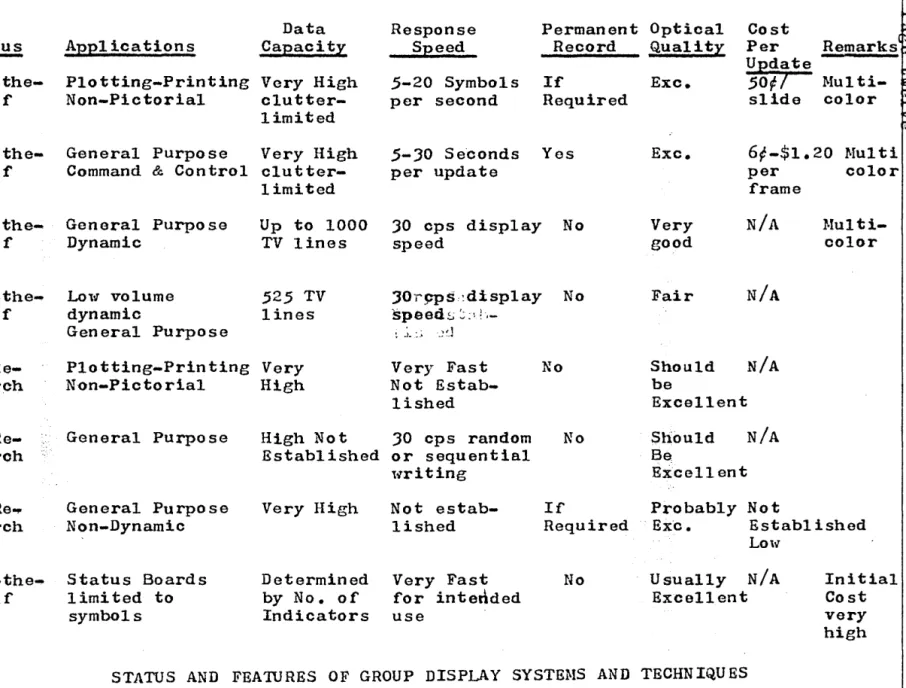
A comparison of present state-oC-the-art large-soroon displays has been f,resented in an HADe report prepared by LaSall
0.:3
A table sho'iing'status and Features of Group Display Systems and Tochniques II in that
report is roproduced here as Table II.
The difficulty of establishing quantitativo moasuros
of
display systemeffeotiveness has been a.ptly stated by LoellTo S
"A thorough understandine of display objectives and
criteria is essential to good display system design.
Unfortunately, there usually arc no
quantitative
measuras of ef~eotlveness for display
systems.
Infaot.
it 1s often diffioult to state olear-out qualitativ~ oriteria. • ••• Laok of a singleClass of' Display
Projection Plotters
Rapid Pro'c'ess Film
Oil Film
Light Valve
Projection Cathode Ray Tube
Status OCf'-the-Shelf' Of'f'-the-Shelf' Off-the-Shelf' Of'f'-the-Shelf'
Eleotro- In
Re-luminesoent search
Matrix Display
Soanned Laser In
Re-Beam ~isplay searoh
Reuseable Film In Re~
Systems search
Alpha Numerio
Indioators
Of:f ...
the-Shelf'
prepared by H.H. LaSalle
of RADC
Applications
Data Capacity
Plotting-Printing Very High
Non-Pictorial
olutter-limited
Response Speed
5-20
Symbols per secondPermanent Optical
Reoord Quality
I:f Required Exc. Cost Per Update
50Ft
slide~
Remarks(§~Iul
ti-~
color ~
~
General Purpose Very High
Command
&
Controlc1utter-limited
.5-30 Se"conds per update
Yes Exc. 6~-$1.20 f.Iulti
General Purpose Dynamic
LalIT volume
dynamic
General Purpose
Up to 1000 TV lines
525
TV lines30
cps display Nospeed
:,JOT'9Ps::disp1ay No
speeds :;;;1
!",-Plotting-Printing Very
Non-Pictorial High
Very Fast Not
Estab-lished
No
General Purpose High Not 30 cps random
Established or sequential lvriting No per f'rame Very good N/A Fair
Should N/A
be
Excellent
Should N/A Be
Excellent
Very High If Probably Not
color
I·IuI
ti-oolor
General Purpose
Non-Dynamic
Not
estab-lished RequiredEx~. Established
Status Boards limited to symbols
Determined by No. of Indicators
Very Fast for intedded use
No
Lo\~
Usually N/A
Excellent
STATUS AND FEATURES OF GROUP DISPLAY SYSTE~IS AND TECHNIQUES
TABLE II
Initial
.---_._--_._--_.---.---.--.
DISPLAY HARD~YARE TECr-L~OLOGY
Page thirteen
'In tho roforenced articlo, he identifies nnd dlscussas dis~lay system
objoctives [!.nc.1 critoria, many of 'vhich are non-(}uantitativn.
Ta.ble I indIcates thoso tcchnolo~_:i0s that ar8 expected to be feasible
for usc in a 1970 sy-stem. lIolvevor, some of tho other technolop.ios that
are not expocted to be fensiblo for a.n oarly 1970 system may develop
sufficiently rapidly that thoy can be includod in i l system b~coming
operational during the later 1970's. TIlcse other technolo~ios should
bo followed closely to permit their consideration for use in a later
system if future developments indicate' earlier feasibility or
additional advantages. Other display teohnologies will probably be
dovelo~ed for use in the latter 1970's that arc not envisioned at this
time. Close attention should be given to the cmcrt};enC0 of such new
tcchnolo~ios. Nc'\' laser techniques Llnd npplications may ~\!'cll fall in this cateGory.
Fina.lly. in any consideration of display teohnologies and solection
of display media or techniques. displa.y user teohnology and softlITare
considerations discussed lat~r will play an important rolo. Since the
display imago is usually ~Bnoratod by a computer initially in 0. naval
ta.ctical system, consideration of hard,.,are -coo!1.l1ologios cannot bo
divorcod from the accompanying tlSGr functions and prorrramming and
com!,utor interfaoo techniquos. For any sol (~ct~d hnrd",aro teohnology.
the requiremonts of the usor and of' the computer l,vil1 place diff'ering
roquirements on tho actual design of specifio disnlny oquipments or
subsystems using tho teohnolo~y. In t~lG same Hay, the choice of
different toohnolo~ios will affect the rnquiromonts placed on the user
and tho computer. ' '
5.
Antioipated Capabilities vs. Navy RequirementsThe oapabilities of display teohnolorn.ESoompared in Section
4.
anddiscussed in Seotion
6.
must be oonsiderod in terms of their abilityto meet Navy requirements as discussed in Section
3.
In previous disoussions, the adequacy and suitability of cathode-ray-tube teohno1ogy for oonsole type displays have been emphasized.
Cathode-ray-tube technology with oontinuing evolutionary improvements is believed to be capable of meeting the requirements for oonso1e
dis-plays for naval taotioal app1ioations during the 1970'so Hence, there
is no urgent requirement for the development of a different teohnology
Cor oonsole displays. On the other hand, if any of the new display
teohnologies considered for largo-screen displays also offer promise of meeting the requirements for console displays, these should be
carefully investigated to determine l~lether they offer advantages over
cathodd-ray-tubes. Even though cathode-ray-tubes represent an
r .
-DISPLAY HARD\vARE TECHNOLOGY
Page fourteen
All
of
the more important and more feasiblo types of displays thatmay be applicable to naval tactical systems in tho
1970
ora havebeen analyzed, evaluated and compared. Particular emphasis has boen
placod on largo-screen displays since they represent the major problem
area due to tho unsuitability of present electromechanical. and photo-graphic approaches tV'ith respect to the naval environment.
Since military taotics change and functional requirements are difficult to state explicitly, flexibility is an important factor in military
display systems. Duffy and Smith have listed four major areas of
concorn from the standpoint of flexibility -- distribution of
information, symbology and coding, format, and growth capability.5 Floxibility in such areas should bo a strong consideration in planning display cquipments and subsystems for naval tactioal systems.
Table I I I presents estimated ratings for each type of display
technology for consolo nnd large-screen display applications. The
ratings shown represent the following oatogorios rather than specific relative valuesz
1. Dovices that will be feasible and that arc recommended
for serious consideration for use in
1970
naval tacticalsyst ems.
2. Devices 'ihose feasibility by
1970
is quostionable at thistime but that may be feasible i f sufficient emphasis is
placed on them. Dovioes in this category are recommendod
for consideration for
1970
naval tactical systems i favailablo and proven foasible.
3.
-Devices that will be obsoleted for mobile tactical useby nelver technologies by 1970. Theso devices are not
recommended for consideration.
This summary is based on the comparisons in Section
J.
and on thotochnical disoussions in Section
6.
Fewor types are listed asoan-didates for console displays because of the diffioulty of oompeting
l'lith. cathodo-rny-tubes. On the basis of' these discussions and
com-parisons, tho followine arc believed to be the most promising
technologies for meohanizing large-soreen displays in
1970
era navaltactical systems:
Photochromic/CRT displays
Thermoplastic and/or photoplastic light valves Electroluminescent uisplays
Lasor inscribing systems.
Ir
subsequent developments indicate that they will be Coasible andavailable, consideration should also be given to:
Solid-stato light valves Opto-magnetic displays Electro-chemical displays
DISPLAY HARDT.1ARE TECI-L""\OLOGY Page f'iftocn
DISPLAY
TECHNOLOGY
Cathodo-Hay-Tube (Diroct Vicu)
?-Iochan ieal
InscribinG Systems
Film
Projoction Systems
Photochromio/CRT Display
Oil-Film
Light Va1vos
CONSOLE
DISPLAYS
x
LAHGE-SCREEN
DISPLAYS
x
x
x
x
TI~ermop1astic and
Photop1astic Light Valves
x
Solid Stato Light Valves
Eloctroluminescent Displa.ys
Opto-Nagnetio Displays
Eleotro-Chomical Displays
Lasor
Insoribing Systems
Laser/Luminoscent
x
x
x
x
x
x
x
x
(or Electro1uminoscent) Displays
NOTE:
-
Numbers in rating column have the followingmeaning:
(1 )
(2 )
( :3)
Recommonded for consideration for 1970 naval tactioal systems.
Feasibility by
1970
questionablo, butshould be considered. if proven fcasibloo
Will bo obsoleted by other technologies
for naval taotical type applications by
early 1970's and not recommended.
DISPLAY TECHNOLOGIES FOR
1970
ERA NAVAL TACTICAL SYSTEMS TABLE IIIRATING
1
J
J
1
J
1
2
1
2
2
1
DISPLAY HARDlvARE TECHNOLOGY Page sixteon
It is difficult ~o decide whether laser/luminescont displays should
be placed in the first or second category. This is a very p'romising
technology. but its feasibility depends upon the development of
adequate powor lasers in the proper frequency range and the ability to
dof'leot laser beams w'ith high resolution cheaply. These '''ill be
developed, but i t is not oertain that this will occur by
1970.
For
largo-screon displays, cost, reliability, maintainability, nndability to meet naval environmental conditions are oriteria of equal
or greater importanoe than th0 ability to moot performance
require-ments. Unfortunatoly. most of the now technologies recommended for
consideration in a
1970
systom havo not been developed far enough atthis time to permit a determination of their relative advantages and
disadvantages with respeot to those oharacteristics. It will be
neoessary to follow those closely during the next year or two to
de-termil1e lihethor indications arise that anyone of them l"ill be more
o~ less suitable from the standpoint of cost, reliability,
maintain-ability. and ability to meet environmental conditions.
Tho major need is for a nOli tec1ll10logy that can provide an
all-solid-state large-screon display using batch-fabrication techniques. n~o
development of suitable batch-fabrication techniques is a goal for display systems, but this is more difficult and is not considered as
oritical as in the case of memorios and logic oomponents. If a
DISPLAY IIAHD\vARS TECHNOLOGY
Page seventeen
6.
Technical Discussion of Diselay TechniquDsSince a number of satisfactory teohniques for console type displays are now available, no problem 1s anticipated with respeot to the
availability of console type displays for a 1970 system. Bxisting
oathode-ray-tube technolOGY and anticipatod improvements in this
technology should meet all requirements for small-screen console typ~
displays, oven if none of the new technologies provo to be superior.b •
7
Ho,,,evor, "tvi th respoct to large-screen displays, tho si tuation is muoh
less ravorablc. In an RADG Technical Documentary ReportS published in
1962, the state-of-the-art and development efforts for large-screen displays were described as follows;
flDisplay developments are being undortaken in three major
technological areas. These areas may be differentiated in
terms of the basic prooesses being applied and on tho basis
of development time required to provide fully operational sUbsystems.
The first of these prooesses is based on projection and
employs a stable light modulator, such as film or
selenium plato, to provide the display. Operational
subsMstoms of this sort are considered to be aohievable 'vi thin mon ths.
The second process, the light valve, 1n theory should
provide adeq~ate performance for systems applications,
and it has the dual advantages of operation at
elec-tronic speeds and of the elimination of' oxpensive film.
However, the performance potentials have not been
realized in practice, and major technologica.l
improvo-ments must be made before the light valve can be useful
for most systems applications.
The
presently availablemodels oxhibi t major \ITcalcnesses in their capabili ty to
provide high resolution and brightness.
This IOly brightness makes i t impossible to use the light
valve in the high-ambiont lighting conditions of most of
the systems. The interaotions of' the oil film and the
lens systems are such that i t is not possible to increase the display brightness level without major improvements in
the characteristics of the modulation surface.
Improve-ment, very likely, is contingent on tho development of
suitable thermoplastic materials. Light valve teohniques
show oonsiderable promise, and with suitable development may
eventually supersede film systems. However, it should be
cloarly rooogniz~d that full realization of the light
nISPLA Y HARD\.,.ARE TECHNOLOGY Page eighteen
The third process, alectroluminescence, does not require projection since the display surfaoe itself acts both as light source and modulator. Only small laboratory devices for'demonstration and experimentation are available at the present time. Electrolumlnescenoe is appealing in its
apparent simplicity, its capability to eliminate projection. and its characteristic of non-catastrophio failure. In
addition, there is a potential for full color operation at high brightness levels, and the large surfaoe reduces the problems of obtaining high rosolution. Unfortunately.
there is an impressive number of technical obstacles that must be overoome beforo electroluminesoent devices can meet the requirements of the systems. The most immediate problem is that of modulating the display surfaoe, and a number of promising efforts are underway in this area at the present time. This effort is concurront l.;ith others that are aimed at the development and application of ne't" phosphors to obtain high brightness levels and multiple
colors. Ho,,,rever, aven allowing for impressive teohnological improvements, years liill be required to advanoe the oap-ability of electroluminescent d~splays to the point ,,,here they oan serve as dynamio large soale displays f~ system
applications. '
Desirable as these advanoed displays are, most immediate requirements of Command and Control Systems can only bo met by projection techniques using film or xerographic techniques for light modulation."
Unfortunately. developments during tho past two years have not
significantly altered the status described above, exoept that improved teohnologie~ such as light valves and eleotroluminescent displays, aro of oourse somet"hat oloser to praotical realization no\~ than they l\Tere
in 1962. These \..rill be discussed in greater detail later.
Photographio projeotion techniques are still the only feasibl~ means available for moeting requirements for large-screen displays in
Command and Control Systems. Significant progress has boen made in light-valve type displays during the last t,.;o years. but the
reliability and life of these devices makes questionable their USe at this time in an operational system in ,.;hloh. minimum dO'tm time is an impo rtan t requ iremen t • IIot'1ever, n e\..r and impro vod 1 igh t-val va type devices offer great promise for a system to be operational in 1970.
Display techniques that have been developed or that appear promising for the future inolude individual oharacter lights. oathode-ray-tubes, meohanioal inscriber systems, film or photographio projection systems, light-valves, photochromic systems, electrOluminescent devices,
ferroelectric devices, opto-magnetio devices, eleotro-ohemica1 and
DISPLAY HARD1'lARE TECHNOLOGY Page nineteen
obsolote by
1970.
Improved light.valvos, eloctroluminescent panels,photochromic displays and, possibly, laser-luminescent displays appear
very promising for that timo perlod. Types of displays, systems
'considerations 'and the more promising display technologies that have
boen investigated are discussed briofly in the follo't-ting parts of
this soc tion.
6.1
Types of DisplaySevora1 different methods of olassifying displays wero disoussed in
Sub-Seotion
2.
It
was pointed out that since this section on displayhard'tlTare is concerned primarily \""ith technologies available for
meohanizing display cquipments and systems, those methods of
classifi-cation will be used that are directly related to technology. Other
sections on display usor-technology and programming are more properly
c6ncerned llTith classifications relating to the functions included in
the equipment, the use for l""hich the equipment is intended, user
considerations, and progrm~m1ng and format considerations. There are
four major types of displays in a category that directly affect the tochno1ogies involved:
Individual character displays and indioators
Consoles
or
individual user displayLarge-sorcon or group displays Hard copy displays.
These can fUrther be subdivided by the technology involved and most of the subsoquent parts of this disoussion will be on that basis.
A number of techniques are currently available for the mechanization
of individual character and indicator type displays. These are
per-haps not ideal, but they aro certainly adequate for present
require-ments; and normal evolutionary improvements and developments should
permit these devices to meet the requiroments imposed by 1970 systems without requiring new technologies or breakthroughs. Honce, these are discussed very briefly.
Console displays are presently meohanized satisfaotorily ,~ith existing
cathode-ray-tube technology. Improved console type displays are
desired for futuro systems, but these improvements are basically a
matter of ongineering design and better determination of user functions
and requirements. Some of the neW technologies discussed for
largc-screen displays (e.g. oloctroluminesoent matrix) may also bo
applicable to certain types of consoles, and these will be pointed out
in subsequent discussions of different tochnologies. However, con- '
tinued improvements and evolutionary developments in cathode-ray-tube technologies will permit console displays meeting all of the require-ments of a 1970 shipboard tactical data system lvithout the necessity
DISPLAY HARn\V'ARE TECHNOLOGY Page tl'lcn ty
n~e same is true for hard copy displays - present toohniques are in
general satisfaotory and.adequate. but there is of course room for improvement and continuing improvements of an engineering nature are
anticipated. Several types of hard copy displays are discussed as
pr{nters in the section on input/output.
.
,
Little time dur~ne the study has been davo"ted to these three types of
dis~lays since existing technology can meet present requirements, and i t is anticipated that normal engineering improvements and evolutionary developments in existing techniquos and technologies ll1il1 meet the
requirements for a
1970
system. Most of the effort during this studyhas been devoted to the typo of display that presents the major prob-lem from the standpoint of technology -- large-screen or group
displays. That is not to say that this is the most important type of
display. Tho oonsole is probably tho most important single type of
display. However, large-screen displays present the major problems.
This is the area in l'lhich presen tly-used systems and approaches are
inadequate for real-time shipboard tactical data systems - the area in
't'lhich nelIT technologies are required to meet the requirements for a
1970
shipboard system.It should be noted that cathodo-ray-tube technology, which is the
heart of most console displays, also plays an important role in many
ourrent and future large-screen display systems. For example. current
photographic film projection displays depend upon cathode-ray-tube
generation of the original image on the film.
6.2 Systems Considerations Affeoting the Selection and Performance
of Display Equipments and Technologies
A display system oonsists of more than a display media. For example.
a typical large-screen film projeotion system
may·
include:A
buffer for storing data from the computerA symbol generator lor converting coded characters into alphanumerio symbols
An image generator for positioning the symbols and graphioal information properly on the face of a cathode-ray-tube to expose the film
Processing equipment for developing the film and
possibly making copies
Film handling mechanisms for transporting the' slides or li1m strip to the projector at the proper time
A projeotor including light souroe and optioal system
A
screenNecessary controls.
DISPLAY HARD~t[ARE TECHNOLOGY Page tt.;onty-ol1e
Symbol 2.2neratlon
For almost all typos of displays, i t is neoessary to convert coded
information
in
computer languageto
shaped oharaoters and symbols ontho vietlTing soreen. This oporation, usually referrod to as character
or symbol generation, may be acoomplished digitally
(e.g.
oonversionfrom
a
6
bit alphanumeric oodoto a
35
bit5x7
dot matrix). or i tmay be accomplished by beam shaping (e.e. a Charactron tube). In a
Charaotrol1 tube, the partioular alphanumoric ooded charaoter causes a deflection of the beam to a partioular aperature on a mask through
'lThich'the beam is passod shaping i t into the corresponding oharaotoro
, S,'," / :i-/ ..
r"
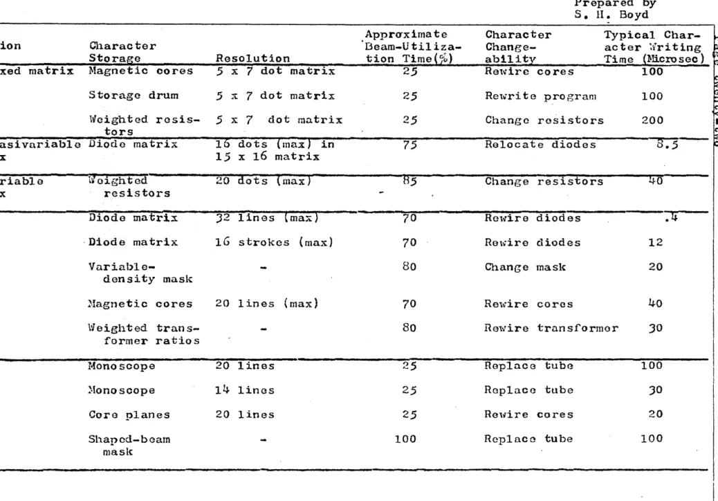
Many types of character and symbol genorators have been
use~f
inciudingdot matrix generators, stroka generators, raster scan gonerators.
and the shaped boam rerer~od
to
previously. Since these techniquesare well established, i t is not neoessary to discuss them in detail
here, but a table comparing character generation techniques pUblished
by Boyd is r';sproduced as Table Iv.9 Similar techniques can be used
fo'r generating a larger oomplement of symbols inoluding speoial
military symbols ~s well as alpha-numerio charaoters.
I
Ambient Light Devices
Display devioos are of t,'lO types: ambient light refl ectors (e.e. hard
copy or dial settings), and self-luminous (o.g. CRT or projection
soreens). Devices whioh have a built-in souroe of illumination purely
to illuminate a reflectlve type surfaco. (for example.,. airoraft
instruments, or other oonventional dial or meter type indicators) fall in the first oategory, since the purpose of the built-in illuminant is
either to replaoe or supplement ambient lighting. Fluorescent marked
dials or indicators do not fall into this category except that they are
frequently used as combination ambient-light and darkness viellTed
devioes, (again. as an example, in aircraft instruments.) The advantages
of fluorescent indicators are two-fold, first, oontrast is inoreased
sinoe the non-fluorescent areas reflect no visible light t and secondly.
the illuminating ultra-violet light souroo. i f shielded from direct
vie,,,. 'tlTill not affect darlc adaptation. In this latter conneotion, i t
should be noted that l.vhere darlc adaptation is important, "ambient.
light" refleotors are built w'ith their 01'111 self-contained illumination,
t'lhose color and intensity oharacteristics may be adjusted to suit the
particular applications. .
TIle important considerations here are the provision of adequate
con-tra.st (both color
dnd
brightness) and suf:ficient grossness of detail. to provide ,legibility at the required viewing distance, and viewing
angles. n~e latt~r requirement imposes the necessity Cor reduoing
parallax,ard avo:i..dJng reoessing and distorting glass or plastio housings.
Contrast for ambient light devices is controlled by adjusting the
reflectivity of the information and background surfaoes. If glass or
Generation 1vlethod
Dot, fixed matrix
Character Storage
Magnetic cores
Storage drum
lieighted
resis-tors
Dot, quasivariable Diode matrix matrix
Dot, 'variable matrix
Stroke
Raster
., : ht d ~ Ol.g e
resistors
Diode matrix
·Diode matrix
Variable-density mask
:Magnetic cores
Weighted trans-former ratios
?-Ianoscape
~Ionoscope
Core planes
Shaped-beam
masl{
Resolution
.5
x7
dot matrix.5
..
~ 7 dot matrix.5
x7
dot matrix16
dots(max)
in1.5 x
16
matrix20 dots
(max)
J2 lines (max)
16
strokes (max)20 lines
(max)
20 lines
14
lines20 lines
Appr<Tximate
I3eam-Utiliza-tion Time(%) 2,5 2,5
2.5
75
85
7070
80
70
80
25
25
2,5 100CO~~ARISON OF CllARACTER-GENERATOR TECHNIQUES
TABLE IV
Prepared by
S. H. Boyd
Character Change-ability
Ret.;ire co re s
Rewrite program
Change resistors
Relocate diodes
Change resistors
Rel'lire diodes
ROl..;ire diodes
Change mask
Re'\~ire cores
Typical
Char-acter ~vriting
Time (~Jicrosec) ,
100
100
200
8 .
.5
-40
.li
12
20
40
nel~ire trans:formor
30
Replace tube 100
Replace tube
30
Relvire cores 20
DISPLAY HARD\'IARE TECHNOLOGY Page twenty-three
high brightness or contrast. Since hooding or tilting the protective
surfaco reduces the viewub10 angle, non-reflectivo coatings may also
b~ required. Circular polarizing shields will be effective only in the
control of specular reflections from tho display surface;' these are
not present, in general, on ambient light devices, or may be elminated
by the application of high reflectivity diffusing paints of the
required color.
A spooial type of tlambient-light" device is available in lvhich the
indicator surfaoe (for example a spinnine drum containing the
charaoters to be viewed) is in continuous motion, nnd a flash lamp is
synohronized to illuminate the surfaae at tho proper rate. Sinco this
device must bo shielded from all o~traneous light to avoid blurring
of the information. it' is more properly classi:ficd as a self-luminous
device in a speoial category of its own. Anothor version of this type
of device has tho strobo lamp mounted insido an opaque drum ,~ith
transparont (cutout) charaotors, and belongs properly in the group of self-luminous devices.
Pro j action Systom (S 01 f-Luminous)
TIle amount of light roaohing the projection screen is a function of' a
number of parameters, but for well designed .optical systoms certain
rules-of-thumbaro applicable. Several useful ones are:
1)
2)
A light vo,lve TV system using a Xenon arc lamp has an
output of between 0.7 and 1.5 lumen/watt.
A 35mm slide projector using an incandescent lamp has an output of between 1 and 2 lumens/watt.
Those are typioal figures only and the limits may be
exceeded by exceptionally 'tV'ell designed or poorly
adjusted equipments.
Ii'or a uniformly dl:ffusing matte sc'reen tho screen brightnoss in
foot-lamberts is equal to the luminous output of tho projector divided by
the scroen area in square feet. For example, the screen brightness
produoed by a 2000iv ~\:al1on light valvo operating at an ou.tput of I '
lumen/lv"att on a 10 ft. square screen is 20 ft. lamberts. Both front
and rear proj cction screens may appear a1 thor brighter or dimmer than :'a
uniform diffuser depending on the nature o~ the sereen and the line of'
viet'l. Tho ratio of brightness is a maximum 1",hen the line of view
extends directly back to tho projector for a rear projection screen, or
along the refleated
ray
from the projector for a front projectionscreen. This maximum value is l"'eferrod to as the gain of the screen.
Typioal useCul screen gains lie in the range of
D.S
to 2.0, althoughhighe'r gain scroons are used ,,,11.en the restricted viewing angles
r - - - ---"--1
DISPL\Y HARD\vAHE TECHNOLOGY
Page tll)'enty-four
The hit~her the screon gain tho hiGher tho contrast. in general. for
both front and rear projection screens. This is tru~ for rear
projeotion soreens sinc~ the reflection of ambient lieht from the
front surface is low with hieh gain screens, and for front projoction screens, the directivity of hieher Gain screens is such that off-axis
ambiont light is not directed into the viel~ine area. An additional
deeree of contrast control is available with rear projoction screens
in that a neutral density frontplate may be incorporated. If the (one
,\vay) transmission is x~'£. the tl'lO '\~ay attenuation of reflected liGht
is x 2
%.
A 50;b faceplato thus attenuates the projected beam by afaotor of 2 and the undeslrable ambiont ro:floction by a factor of
4.
Brightness and Contrast
Hoasures and stanuarrls for some display system parameters, such as brightness and contrast ratio, arc difficult to ostablish because of
variations in viouin8 conditions and ambient light. Because 01 all of'
the variables introduced by the screen parameters and the ambiont
lighting condi tions. it is not practicable to assign a brightness and contrast value to a projection system without defining the viewing
conditions. I t is for this reason that projection systems are best
defined in terms of lumens output. Brightness in foot-lamberts for 'a
unity gain screen is obtained by dividing by the screen aroa square
feet. Contrast is obtained by multiplying tho ambient light in
:foot candl'os by the screen rerloctivity coefficient. and computing
the ratio of "light" to "dark" values.
Typical values of brightness and contrast are given in Table V for
several modia as an indication of relative levels and variability.
In Table V • note that pulsed EL Mosaic panels have brightnesses
oomparabl e t~i th TV raster. or open gate thea tre soreens. If tho
contrast lovel ShOlom for llThi to-on-dark textual copy is inoreasod. the
legibility o~ fine detail degrades with inoreasing contrast if the eye
DISPLAY HARD'vARE TECHNOLOGY
Page t'tven ty-fi ve
TYPICAL BRIGHTNESSES - FOOT LA~IBERTS
SurCaoe of the Sun
Surfaco of a
60w
frosted incandescent bulbSurfaoe of a 60\v "ltlhiteff inoandesoent bulb
Surface of a
lSW
fluorescent tube\fuite paper in diroct sunlight
Clear
sky
n~eatre screen open gate
Surface of the ?oIoon. bright area
White paper on office desk
Pulsed EL Mosaic Panel
TV Raster on CRT
36,000
9,000
3.000
9,000
2,000
16
7.50
2.5
20
20
Light valve, lOr x 10' diffusing screen, 2KW Lamp 20
CONTRAST LEVELS
Textual copy (tvhi te-on-darl<:) 10:1
Line drawings and black .. on-l'lhi te text
Photographs 100:1
NOTE: Figures above were extraoted from an unpublished
technical manuscript prepared by Dr. H. R. Luxenberg.