Effect of Pressure Application by HIP on Microstructure Evolution
during Diffusion Bonding
Naoya Masahashi
*1and Shuji Hanada
*2Institute for Materials Research, Tohoku University, Sendai 980-8577, Japan
The effect of pressure application by hot isostatic press (HIP) during diffusion bonding on microstructure evolution and bonding strength was studied using a couple of an Fe–Al alloy (Fe–Al) and CrMo steel (CrMo). Columnar microstructure evolution from the joint interface to the CrMo side is suppressed and aluminum diffusion from Fe–Al to CrMo is retarded with pressure application. Refined microstructure with fine precipitates is observed in the CrMo side beyond the columnar grains of the couple bonded with pressure. The application of pressure decreases the bonding strength and the strain to failure. It is concluded that the application of pressure provides microstructure refinement and strong hardening in the CrMo side of the couple, although it is not beneficial for bonding strength.
(Received April 8, 2005; Accepted May 24, 2005; Published July 15, 2005)
Keywords: diffusion bonding, hot isostatic pressing (HIP), orientation imaging microscopy (OIM), hardness, iron aluminum alloys
1. Introduction
Diffusion bonding has been widely used to produce reliable interfaces between similar and dissimilar materials in electronic, nuclear and aerospace industries.1,2) Bonding
across an original joint interface is achieved through a plastic collapse of surface oxides and subsequent atomic interdiffu-sion, recrystallization and/or grain growth with applying a moderate pressure.3)Petersonet al.reported that temperature, pressure, and holding time are the three main variables governing the integrity of the diffusion bonding.4)Moreover, mechanical and microstructural properties are the other important parameters in diffusion bonding.5) According to
Petersonet al., the bonding pressure is selected to cause local plastic flow of at least one component adjacent to the interface to plug the interfacial voids and disperse surface oxide. In this method, mating materials are brought into contact under a pressure far below the yield strengths of the materials, and the bonding temperature is selected to
0:7{0:9Tm (Tm is the melting point of the lower melting
constituent). Then, the microstructure of the bond region is similar to that of regions remote from the joint interface and has parent metal properties.6) Uni-axial low pressure of 3– 10 MPa is typically applied to the materials, whereas isostatic high pressure of 100–200 MPa is applied by HIP (Hot Isostatic Press).1)Since the application of high pressure by HIP eliminates the incorporated porosity and enables the bonding of materials,7)it is expected to increase the bonding
strength.
The authors have proposed composite laminates consisting of an iron aluminum (Fe–Al) alloy and a certain type of steel to provide the steel with additional properties, such as corrosion resistance, strength and light weight.8–10)
Funda-mental studies using diffusion couples consisting of Fe–Al and steel have been carried out focusing on microstructure evolution, diffusion behavior and corrosion resistance.11,12)In the couple bonded at temperatures above A3(gamma to alpha transformation temperature), the columnar grains are evolved
from the joint interface toward the steel side and strengthen the bonding between materials. DeLeeuw reported that effective diffusion bonding of SiC was achievable by applying interfacial pressure of 27 MPa from the measure-ment of the joint strength, while they did not study the effect of pressure application on microstructure.13) The effect of
high-pressure application by HIP during diffusion bonding on microstructure evolution has not yet been reported to the best of our knowledge. The objective of this paper is to explore the effect of pressure application on the microstructure evolution during diffusion bonding focusing on the develop-ment of columnar grains, and the bonding strength between the mating materials.
2. Experimental
The compositions of the Fe–Al alloy and the steel are Fe– 20 at % Al (abbreviated as 20Al) and Fe–5.4 at % Cr–0.3 at % Mo (CrMo) steel, respectively. The composition of CrMo is similar to that of commercially produced alloys. All the samples were prepared by argon arc melting, followed by hot rolling of 20Al at 1273 K and cold rolling of CrMo to 5 mm resulting in approximately 50% reduction. 20Al exhibits equi-axed coarse grains ranging from 300mmto 1 mm while CrMo exhibits a deformation microstructure.
Specimens of 51010mm3 were sectioned from the rolled plates using an electro-discharge machine, and the contact surfaces were mechanically polished by SiC paper, and 1.0mmalumina particles. The polished specimens were clamped by alumina jigs applying weak pressure. Diffusion bonding was conducted by two methods. For ordinary bonding, diffusion bonding was carried out at 1323 K for 3 h, 48 h and 96 h in a vacuum less than210 3Pa followed by cooling in a furnace. For bonding with pressure, the pre-bonded couples that underwent diffusion bonding at 1323 K for 3 h were isostatically pressed by HIP (Kobe Steel, O2-Dr. HIP) at 1323 K for 3, 48 and 96 h applying 196 MPa in an Ar atmosphere, followed by cooling in a furnace. The couples prepared by each method are described as DB and HIP in the above sequence. And each DB couple will be referred to as DB3, DB48 and DB96, when the bonding time was 3 h, 48 h
and 96 h, respectively.
All the couples were cut into two pieces perpendicular to the joint interface, and their surfaces were mechanically polished by emery paper and alumina particles, followed by chemical polishing using a colloidal silica suspension with a particle size of approximately 0.04mm. One of the pieces was supplied for microstructure observation, micro-Vickers measurement, XRD (PANalytical X’PERT MPD) and OIM (TexSEM Laboratories; linked with a Phillips XL-30 FEG SEM) analysis. The other piece was polished to the size of about 4:84:810mm3 and subjected to a mechanical shear test at a loading rate of 8:310 4s 1. Detail of the testing procedure is described elsewhere.12)
3. Results and Discussion
3.1 Microstructures
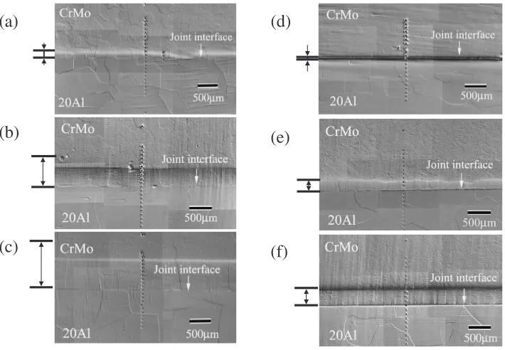
Figure 1 shows the optical micrographs of DB and HIP couples. The average length of columnar grains is indicated by the arrow on the left side of the micrograph. The columnar microstructure evolution from the joint interface toward the CrMo side is observed in all the couples. For the DB couples,
equi-axed microstructures are observed beyond the columnar grains and its grain size increases with bonding time. For the HIP couples, fine microstructure with fine precipitates is observed in the same region of HIP48 (Fig. 1(e)) and HIP96 (Fig. 1(f)) while it is not observed in HIP3 (Fig. 1(d)). The microstructure of HIP96 in this region is finer than that of HIP48. There is no difference in the microstructure of the 20Al side between the DB and HIP couples.
Figure 2 shows a plot of the variation of the average length of the columnar grain (a) and the aluminum diffusion distance (b) against the bonding time. The diffusion distance of aluminum is defined as the distance between the joint interface and the site wherein the aluminum concentration is zero in the concentration profile. It can be seen that the growth rate of the columnar grains of the HIP and DB couples is 3.4 and 11.1mm/h, respectively. The average length of the columnar grain is longer than the diffusion distance of aluminum in all the couples, which is similar to the previous studies.9,12) The increase rate of the aluminum diffusion distance in the DB couples is higher than that in the HIP couples. Consequently, the application of pressure suppresses the columnar grain evolution and retards the aluminum
(b)
(c)
(a)
(f)
(e)
(d)
Fig. 1 Optical micrographs of the joint interface vicinity of DB3 (a), DB48 (b), DB96 (c), HIP3 (d), HIP48 (e) and HIP96 (f).
1 10 100
0 500 1000 1500
(a) HIP DB
Length of columnar grains,
l
/
µ
m
Time, t/ h
1 10 100
0 500 1000 1500
(b) HIP DB
Dif
fusion distance of
Al /
µ
m
Time, t/ h
[image:2.595.121.476.71.317.2] [image:2.595.135.463.364.476.2]diffusion. Similar result is found in the couple of Fe–Al and a high carbon steel, and the retardation of aluminum diffusion is explained by the carbide phase (Fe3AlC) coexisting with ferrite in the high carbon steel.14)The initial phase in CrMo
[image:3.595.121.478.69.356.2]before diffusion bonding was ferrite, and HIP treatment induces fine precipitates in the matrix. This precipitate might retard the aluminum diffusion from 20Al to CrMo and suppress the evolution of the columnar grains. Another possible explanation for the retardation of the aluminum diffusion could be provided in terms of the self-diffusion coefficient that decreases with the application of pressure due to the reduction of the equilibrium concentration of the vacancies.15)
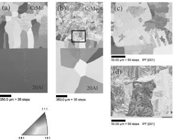
Figure 3 shows the OIM map of DB48 (a), HIP48 (b) (c) and HIP96 (d). The OIM maps show the orientation of the crystalline lattice plane that is aligned with the surface. The average length of the columnar grain of DB48 is longer than that of HIP48, and a refined microstructure is observed in the CrMo side beyond the columnar grains in HIP48. The rectangular area in (b) is analyzed with fine step in OIM analysis (c), showing that each grain is divided by fine facets and some of the facets develop from the grain boundaries into the grain interior. Similar orientation map of HIP96 shown in (d) exhibits an extremely fine microstructure. Figure 4 shows XRD profiles of DB96 and HIP96 using a mono-capillary with 100mm in diameter. X-ray beam was focused on the region of 1.5 mm away from the joint interface in the CrMo side. All the detected peaks in DB96 are assigned to bcc phase, whereas extra peaks other than bcc are detected in HIP96. It is speculated that these extra peaks are due to the precipitates observed in the CrMo side of the HIP couples. TEM study is in progress to identify this phase.
3.2 Mechanical properties
Figure 5 shows a plot of hardness variation against the distance from the joint interface of the couples bonded with short time (a) and long time (b). The hardness changed continuously from the CrMo side to the 20Al side in the couples bonded with short time irrespective of pressure application. This hardness change is also found in the DB couples bonded with long time. On the other hand, the strong hardening in the CrMo side beyond the columnar grains is observed in the HIP couples bonded with long time (b), and the hardness of HIP96 is higher than that of HIP48. This hardening is due to the fine microstructure with precipitates, because the hardened region is well corresponding to the fine microstructure. The hardening is observed in a limited region
20Al
20Al
(d)
Fig. 3 OIM maps of the joint interface vicinity of DB48 (a), HIP48 (b), and the CrMo side beyond the columnar grains of HIP48 (c) (rectangle area in (b)) and HIP96 (d).
30° 40° 50° 60° 70° 80° 90°
Intensity (abs.units)
2
θ
(a) HIP96 (b) DB96
bcc
[image:3.595.320.533.406.567.2]in the CrMo side beyond the columnar grains, wherein aluminium does not exist. This suggests that chemical composition influences the evolution of fine microstructure. Moreover, it is interesting to note that the fine precipitates are observed in the same region. Consideration based on the free energy of the related phases is under way to elucidate the reason for the microstructure evolution.
Figure 6 shows shear stress versus shear strain curves of DB (a) and HIP couples (b). The inserted figures in (a) and (b)
are external view of DB3 and HIP3 after shear test, respectively. The bonding strength and strain to failure of the HIP couples are lower than those of the DB couples irrespective of bonding time. The maximum shear strength increases with the bonding time for both couples. Figure 7 shows fractographs of DB3 (a) and HIP3 (b) with chemical compositions at the fractured surfaces analyzed by SEM-EDX. From the chemical composition of the fractured surface, it is concluded that the HIP3 couple fractured along
−30000 −2000 −1000 0 1000 2000 3000 100
200 300 400 500
CrMo 20Al
(b)
HIP48 HIP96
DB96 DB48
V
ick
ers hardness / Hv
Distance, d / µm DB48 DB96 HIP48 HIP96
−30000 −2000 −1000 0 1000 2000 3000 100
200 300 400
(a)
CrMo 20Al
V
ick
ers hardness / Hv
Distance, d / µm HIP3 DB3
Fig. 5 Variation of the hardness with respect to the distance from the joint interface of the couples bonded with short time (a) and long time (b).
0 100 200 300 400
(a)
0.1 DB3 DB48
DB96
Stress,
Strain
0 100 200 300 400
(b)
HIP3
0.1 HIP48
HIP96
Strain
σ
/ MP
a
Stress,
σ
/ MP
a
Fig. 6 Shear stress versus shear strain curves of DB (a) and HIP (b).
sample No. Fe / at % Al / at % Cr / at % Mo / at % 1 93.3
79.8 79.9
0.4 5.7 0.6
2 19.7 0.3 0.2
DB3
3 19.5 0.4 0.2
4 92.7 1.4
5 93.1 0.5
HIP3
6 93.4 0.8
5.4 5.8 5.5
0.5 0.6 0.3
[image:4.595.136.461.75.187.2] [image:4.595.136.461.237.351.2] [image:4.595.137.460.390.639.2]that the bonding strength of the DB couple is higher than that of the HIP couple. From these results, it is concluded that the bonding strength is not controlled by the mechanical proper-ties of the individual mating materials, but by the interdiffu-sion between the materials. If the bonding strength is controlled by interdiffusion, HIP treatment is not beneficial to increase the bonding strength, although it provides a hardening of the CrMo side.
4. Conclusions
(1) Columnar microstructure has evolved toward the CrMo side from the joint interface irrespective of pressure application. The average length of the columnar grain of the HIP couples is shorter than that of the DB couples.
(2) The diffusion distance of aluminum of the DB couples is longer than that of the HIP couples. The average length of the columnar grain is longer than the aluminum diffusion distance in all the couples. (3) The refined microstructure with fine precipitates is
observed in the CrMo side beyond the columnar grains in the couples bonded with pressure for long time and strong hardening is found in the region.
(4) The bonding strength and the strain to failure decrease with pressure application, while they increase with an increase in the bonding time irrespective of pressure application. This implies that the bonding strength is controlled by interdiffusion between the mating materi-als.
by Mr. Tokuno during the HIP treatment process. A part of this work was performed at the Laboratory for Advanced Materials, Institute for Materials Research, Tohoku Univer-sity. One of the authors (NM) would like to thank the Toray Science Foundation for the provision of a research grant.
REFERENCES
1) G. Cam and M. Kocak: Int. Mater. Rev.43(1998) 1–44.
2) W. H. King and W. A. Owczarski: Welding Journal46(1967) 289–298. 3) C. L. Cline: Welding Journal45(1966) 481–489.
4) K. A. Peterson, I. Dutta and M. Chen: J. Mater. Processing Technol.
145(2004) 99–108.
5) N. Orhan, M. Aksoy and M. Eroglu: Acta Metall. Mater.41(1993) 3077–3084.
6) M. F. Islam and N. Ridley: Scr. Mater.38(1998) 1187–1193. 7) H. D. B. Raes: Powder Metallurgy26(1983) 193–199.
8) N. Masahashi, N. Kondo and S. Hanada: Annales de Chimie Science des Materiaux27(2002) S231–S242.
9) N. Masahashi and S. Hanada: ISIJ Int.44(2004) 878–885.
10) N. Masahashi, K. Komatsu, S. Watanabe and S. Hanada: J. Alloys Compd.379(2004) 272–279.
11) N. Masahashi, G. Kimura, M. Oku, K. Komatsu, S. Watanabe and S. Hanada: Corros. Sci. (2005) in press.
12) N. Masahashi, S. Watanabe, N. Nomura, S. Semboshi and S. Hanada: Intermetallics13(2005) 717–726.
13) D. DeLeeuw: J. Am. Ceram. Soc.5(1992) 72–75.
14) K. Komatsu, N. Masahashi, S. Watanabe and S. Hanada: Collected Abstracts of the 2003 Spring Meeting of the Japan Inst. Metals (1999) pp. 260.