Heating of Metal Particles in a Single-Mode Microwave Applicator
Noboru Yoshikawa, Etsuko Ishizuka
*and Shoji Taniguchi
Graduate School of Environmental Studies, Tohoku University, Sendai 980-8579, Japan
Microwave (MW) heating behavior of various metal particles was investigated using a single-mode applicator. Considering the distributions of the electromagnetic fields in the wave guide, specimens were placed at four specific positions with respect to the electric and the magnetic fields of MW. They were heated at conditions of constant power input.
It was demonstrated that iron particles were heated well in the magnetic field, and that ferro-magnetic metal particles having the higher Curie point was heated the better. It was possible to heat iron bulk particles (3mm) in a magnetic field without occurrence of electric discharge. In the range of nickel particle size between 45 and 150mm, the particles with the smaller size were heated the better.
Nickel oxide (NiO) was heated well only in the position of large electric field, which indicates that the heating was caused by the different (dielectric heating) mechanism from the metal particles.
From these results, contribution of magnetic field to heating metal particles was discussed, considering the heating mechanisms of the magnetic loss and the eddy current loss. The dependence of the heating rate of metal particles on their size was discussed in terms of the heat transfer rate.
(Received November 1, 2005; Accepted January 23, 2006; Published March 15, 2006)
Keywords: microwave, metal particle, heating, electromagnetic field, single mode, ferromagnetic, dielectric
1. Introduction
MW heating has been remarked for various heating applications, such as from domestic cooking oven to immobilization of hazardous elements in the waste by vitrification.1)Their application can be classified with respect to the heating temperature. The heating temperature is usually lower (mostly below 500C)2)in the application of cooking, drying and some chemical processes such as organic/inorganic synthesis.3)In most of the cases, heating mechanism is the dielectric loss of the molecules.4)
On the other hand, MW heating for sintering of ceramics, immobilization by vitrification and solid-state chemical reaction in materials require high temperature above 500C. In the high temperature heating of these inorganic
materials, MW heating mechanism is not only the dielectric loss but differs with the materials. Magnetic properties of the materials are closely related to their MW heating behaviors. Therefore, the eddy current loss (induction heating) and magnetic loss have to be taken into consideration,2,5)both for the metal and ceramic materials.
Recently, MW sintering of metals has been reported.6,7) MW heating of metals has been attempted8,9) and it was applied to chemical reactions.10)Moreover, for clarification of the MW heating mechanisms of metals, Penn state group has performed experiments using a single mode MW applicator.11) They placed metal specimens in the area of either large electric (E-) field or large magnetic (M-) field in the applicator. They examined the heating behavior of various materials and discussed the effects of E-field and M-field on the heating of metals.
In this study, it is also intended to investigate the heating behaviors of metal particles in a single mode MW applicator at the well-defined E- and H-fields for the following purposes:
(1) Further consideration on the E- and H-field distributions
in a single mode applicator by means of simulation of the MW electromagnetic field.
(2) To investigate the difference in heating behaviors of various ferro-magnetic metal particles and of other materials, and to find the dependence of heating behavior on their grain size.
(3) To discuss the MW heating rates of metal particles in relation with their heating mechanisms.
2. Experimental
In this study, a single-mode MW applicator (Nikoha MKN-152-359, max 1.5 kW, Yokohama, Japan) was utilized, which have a wave-guide of TE10m (m¼5{6) mode. A sample holder was placed in the wave guide. Heating was performed at a constant input power (Pf, 0.2 kW) with tuning the power of the reflected (reverse) wave (Pr) to be minimized by manipulating the three-stubs, manually. Movable plunger is set at the end of the wave-guide, which acts as a metal wall and the wave is reflected. The apparatus is schematically illustrated in Fig. 1.
The chamber is a silica glass tube of 50 mm in diameter, where Ar gas was flowing at the atmospheric pressure. Specimens for heating were powder or particle states and they are contained in a holder made of a silica glass having 15 mm in diameter and 10 mm in depth. The clearance between the specimen powder and the holder was filled with an adiabatic material (Kaowool blanket, Isolite Kogyo, Inc., Tokyo, Japan). The specimen holder was inserted into the applicator chamber, at different positions with respect to the E- and the H-intensities.
Temperature measurement of the MW-heated specimens was performed with an optical method (PhotoriX system, Luxtron, Santa Clara, CA, USA), using a sapphire rod for the light guide. The temperature data were digitally recorded in a personal computer (PC). In this method, it is not possible to measure the specimen temperature below 300C, thus the obtained heating curves lack the data at the initial heating *Graduate Student, Tohoku University
stage from the room temperature. The initial temperature varied with the circumferential conditions, however, the temperature measurement above 500C was proved correct
by calibration with thermocouple. Because the heating operation was manually controlled, the heating curves are not smooth (Fig. 4).
The specimen particles are the commercial grade powders (purity 3 nines, Kojundo Chemistry Laboratory Co. Ltd., Saitama, Japan) and have almost spherical shapes. Some of the particle size are indicated by the mesh classification and some are by the average size.
In this study, steady state distributions of the electric (E-) and the magnetic (H-) fields were calculated using a commercial software (Wave-J!, Photon Ltd. Kyoto, Japan).
3. Results
3.1 Simulation of electromagnetic field distributions in a single mode applicator
Calculated distributions of E- and H-field in the wave-guide are illustrated in Fig. 2, the right hand side is the plunger (metal wall). The shown distributions of the field are
the magnitude of the vectorE,H. There is only Eycomponent
inEfield, on the other hand Hzand Hxcomponents exist inH
field. There are five peaks in the electric field, but there are various peaks of the magnetic field. The H peaks at the central area are due to the Hx, on the other hand, the H peaks
in the edge area are due to the Hz. These distributions are
consistent with the analytical solutions.12)
Considering the two distributions and their symmetries, it is pointed out that there are four specific positions with respect to the E- and H-conditions, as illustrated in Fig. 2. J. Cheng et al.11) placed a specimen in either position of 1A and 1B, and compared the heating behavior.
In this study, it is intended to place a specimen at one of the four positions and to investigate its heating behavior. Before this, it is of importance to examine how the distributions are distorted by existence of the specimens. Figure 3 illustrates an example of the simulation result that a dielectric material
ð"0¼8:42; "00¼0:115Þ is placed in the single mode
appli-cator. It is shown that alteration in the field distribution and in the intensity occurred by the dielectric specimen in the area indicated by arrows, however, most of the distributions have the same characteristic features of the wave-guide as shown
(a)
PC
Plan-view of specimen chamber Signal
converter Light guide
plunger
(b)
Water coilspot A
spot B
plunger MW wave
generator
Isolator
Controller
Power monitor
3 Stabs
Wave guide
Specimen Chamber
Water cooling system
Fig. 1 Schematic illustration of experimental apparatus. (a) Side view (whole system) and (b) plan view of the specimen chamber area (a dotted area in (a)).
1
A: E
max, H=0
1
B: E=0,
H
large2
A: E=0,
H
max2
B: E=0,
H=0
E
H
A
B
A
B
2 1
2 1
(a) Electric field (E)
(b) Magnetic field (H)
arbit. scale
arbit. scale
high
high low
low
[image:2.595.114.475.75.203.2] [image:2.595.129.468.249.474.2]in Fig. 2. This tendency is different from the aspects in the multi-mode applicator.13)
In this study, metal particles are heated in the applicator. So, it is needed to examine the alteration of E- and H-fields by the metal particles. However, the simulation is not necessarily easy. A discussion will be made later in this regards.
3.2 Heating behaviors of various materials in different E-, H-fields
First, heating behavior of nickel oxide (NiO) particles having 7 microns in diameter was investigated. The obtained heating curves are shown in Fig. 4(a). The particles were heated only at the large Ey position (1A). NiO is a
non-magnetic (anti-ferro magnetism) ceramic material and it has low electric conductivity (<11012Scm1) below 50C. Therefore, NiO was not heated neither by the mechanism of magnetic loss nor by the eddy current loss, but by that of the dielectric loss. The other (non-magnetic) ceramic material was also heated in the electric field. These results are consistent with the report.11)
Second, heating behavior of iron particles having size of 200 mesh (75mm) was observed. The results are shown in Fig. 4(b). The particles were heated best at the position of largest Hx(2A), then at large Hz(1B). It was not heated at the
(a) Electric field
(b) Magnetic field
arbit. scale
arbit. scale
high
high low
low
Fig. 3 Simulated distributions of (a) electric and (b) magnetic fields with insertion of dielectric material. The position of the specimen is indicated with arrows in both fields.
200 400 600 800 1000 1200
0 200 400 600 800
NiO
1A 1B 2A 2B
Temperature, T /
o C
Time, t / s
(a)
200 400 600 800 1000
0 200 400 600
(e)
45 µm 63 µm 150 µm
Temperature, T /
o C
Time, t / s Ni : various size
2A position
200 400 600 800 1000 1200
0 200 400 600 800
Fe 200mesh 1A 1B 2A 2B
Temperature, T /
o C
Time, t / s
(b)
300 400 500 600 700 800 900
0 200 400 600
(d) Cu 1A
Cu 2A Fe 1A Fe 2A
Temperature, T /
o C
Time, t / s Fe, Cu 8 mesh
Occurrence of electric discharge
200 400 600 800 1000 1200 1400
0 100 200 300 400 500 600
(c) Co
Fe Ni
Temperature, T /
o C
Time, t / s Ferro-magnetic metal particles
2A position
[image:3.595.48.290.70.325.2] [image:3.595.102.497.394.750.2]position of zero E-, H-field (2B), and was heated a little at the position of largest Ey(1A). This result is consistent with the
prediction for the MW heating of metals due to the magnetic loss and the eddy current loss mechanisms.
Next, various ferro-magnetic metal particles were heated under the same conditions (same position, same input power and similar particle sizes, 70mm). Figure 4(c) shows the comparison of their heating curves at 2A position. It is shown that Co particles were heated best, then followed by iron and nickel in this order. This tendency is correlated with the Curie point of the metals, namely, 1131C (Co), 770C (Fe) and 358C (Ni). MW heating mechanism by the magnetic loss is kept active to higher temperature in the case of metals having higher Curie point.
[image:4.595.100.497.81.242.2]Heating of metal particles was dependent on their particle size. It was shown in Fig. 4(d) that Cu particles having diameter of>2mm (8 mesh) was not heated well in 2A, and only heated by occurrence of electric discharge in 1A position of large electric field. On the other hand, iron particles of this size were heated well in 2A position [Fig. 4(d)] without occurrence of electric discharge.
Most of the metal particles is heated by MW, however the heating was dependent on the particle size. Usually, it was not possible to heat the milli-meter sized particles without electric discharge, except the ferro-magnetic (iron) particles shown above. The dependence of heating rate on the particle size was also investigated for the nickel particles placed at 2A position. The position was selected in order to observe the contribution of the magnetic field to the heating of metal particles. They are plotted in Fig. 4(e). They were heated better as the decrease of the grain size among the specimens tested. In these cases, Ni particles were heated above the Curie point. Therefore, heating in this temperature range was not caused by the mechanism of the magnetic loss but by the eddy current loss.
4. Discussion
4.1 Heating mechanism of metal particles
In heating the ferro-magnetic metal particles, magnetic loss and eddy current loss are taken into consideration for the heating mechanisms.7) However, the magnetic loss
mecha-nism disappears above the Curie point, thus only the eddy current loss becomes active. Both mechanisms are active only within the skin depth, where the magnetic field can permeate into metals. There is an experimental report on the nitridation reaction within a skin depth of metals heated by 28 GHz MW.14)The skin depth of iron is of an order of 1 micron above the Curie point (in a paramagnetic state) and of 0.1 micron below the Curie point (in a ferro-magnetic state), depending on the magnetic permeability (). (Though it is needed to consider the fact15)that the magnetic permeability of iron particles has the grain size dependence and have a maximum at the size of 1 micron.)
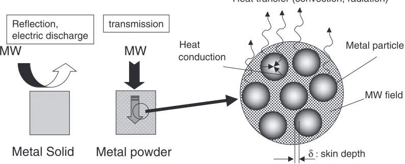
Nevertheless, it has to be noted that the grain size of the particles examined in this study was much larger than the skin depth. Therefore, the MW heating rate of the metal particles might be determined due to the competition among the heating rate of the surface layer (within the skin depth), the rate of heat conduction into the particle center and the rate of heat transfer (either by convection or by radiation) to the air (Ar), as schematically illustrated in Fig. 5. Heating of large metal particles is difficult, because of large heat loss by conduction into the particle center from the thin heating layer. Here, assuming this overall mechanism on the heating rate, it is pointed out that magnitude of the magnetic loss effect is larger than that of the eddy current loss, because non-magnetic metals having millimeter size cannot be heated only by the eddy current loss. On the other hand, it also has to be noted that ferromagnetic metal particles such as Co were heated above the Curie point. The eddy current loss might be important. Heat insulation condition also determines the attained maximum temperature. More quantitative experi-ments will be performed to discuss the rates in future study.
4.2 Consideration of the electromagnetic field distribu-tion
The disturbance was caused not only in the E-filed but also in H-field by the dielectrics (Fig. 3). Similarly, it is expected that existence of the metal particles also causes the disturbance of both E- and H-fields in the applicator. Namely, it is expected that some magnetic components are generated due to the existence of metal particles in the area of the E-field (1A). However, there are no studies reported to the Heat
conduction
MW
Metal Solid
MW
Metal powder
Reflection,electric discharge
transmission
δ :skin depth
Metal particle
MW field Heat transfer (convection, radiation)
authors’ knowledge, which dealt with this kind of the problem.
In calculating the modified distributions of E- and H-field with existence of metal particles, it is needed to propose a microscopic model considering the infiltration of electro-magnetic wave into the metal powder bed. Although the electromagnetic wave is reflected on the flat shiny metal surface of a metal solid, the electromagnetic wave can infiltrate into the metal particle beds with formation of the skin layer in each particle, as schematically illustrated in Fig. 5. These states have to be taken into consideration in the model. If the electromagnetic field analysis of MW in the powder bed becomes possible, it enables the simulation of the sintering in powder metallurgy, and possibly contributes to the more detailed analysis of the metal heating rates.
5. Conclusion
Heating behavior of metal particles in a single-mode microwave applicator was investigated and the following conclusions were obtained:
(1) According to the simulation results of the periodic field distributions, it was pointed out that there are four specific positions with respect to the electric and magnetic fields and that overall shape of the field is not disturbed very much by placement of dielectric materials.
(2) It was shown that the iron particles were heated well at the position of the largest magnetic field. The ferro-magnetic metal powder having the higher Curie point was heated the better. Nickel oxide was heated only in the position of high electric field.
(3) Heating behavior of nickel powder above Curie point was dependent on the grain size. Finer particles were heated better in the range between 45 and 150mm. The heating rate of the metal powder was discussed in terms of the magnetic loss and the eddy current loss mechanisms.
Acknowledgement
Authors are grateful for the stimulating discussions with Prof. D. Agrawal at Penn State Univ., USA and Motoyasu. Sato at National Institute of Fusion Science, Japan. This study was conducted partly with a financial support by Grant in Aid for Scientific Research (A), (15206083), JSPS. The technical advice for handling single mode applicator given by Dr. H. Hukushima is greatly acknowleged.
REFERENCES
1) H. S. Tai and C. J. G. Jou and J. Hazardous: Mater.B65(1999) 267– 275.
2) R. Roy, R. Peelamedu, C. Grimes, J. Cheng and D. Agrawal: J. Mater. Res.17(2002) 3008–3011.
3) D. M. P. Mingos and D. R. Baghurst: Chem. Soc. Rev.20(1991) 1–47. 4) D. E. Clark, D. C. Foltz and J. K. West: Mater. Sci. Eng. A287(2000)
153–158.
5) ‘‘Microwave Processing of Materials’’, Ed. By D. F. Stein, Publication NMAB-473, National Academy Press, Washington D.C. (1994) pp. 29. 6) R. Roy, D. Agrawal, J. Cheng and S. Gedevanishvlli: Nature 399
(1999) 668–670.
7) S. Gedevanishli, D. Agrawal and R. Roy: J. Mater. Sci. Lett.18(1999) 665–668.
8) J. W. Walkiewicz, A. E. Clark and S. L. McGill: Min. Metall. Proc.5 (1988) 39–42.
9) E. P. Bescher, U. Serkar and J. D. Mackenzie: MRS Symp. Proc.269 (1992) 371–378.
10) A. G. Whittaker and D. P. Mingos: J. Chem. Soc. Dalton Trans. (1995) 2073–2079.
11) J. Cheng, R. Roy and D. Agrawal: J. Mater. Sci. Lett.20(2001) 1651– 1563.
12) J. D. Kraus and K. R. Carver: ‘‘Electromagnetics’’, 2’nd Ed., (Mcgraw-Hill Kogakusha, Tokyo, 1973) pp. 540.
13) Chen Yan, Doctor Thesis, Tohoku University (2004).
14) H. Takizawa, M. Iwasaki, T. Kimura, A. Fujiwara, N. Haze and T. Endo: Trans. MRS-J27(2002) 51–54.