New Compo-Casting Method of Ceramics Inserted Cast Iron
Reducing Thermal Stress
*Yoshihiro Tomita and Haruyoshi Sumimoto
Department of Mechanical Engineering, Faculty of Science and Engineering, Kinki University, Higashiosaka 577-8502, Japan
The compo-casting of ceramics by cast iron is expected to be one of the useful casting process that can expand the application fields of cast iron. The largest problem in compo-casting method is cracking caused by thermal shock. Although this cracking can be prevented by reducing the thermal stress by preheating ceramics, the necessary preheating temperature is high and its precise control is difficult at practical foundries. In this study, we tried to estimate numerically the critical preheating temperature of ceramics using the thermal stress analysis during transient thermal conduction and the Newman’s diagram. We also found that the preheating of ceramics to reduce thermal stress can be replaced with placing an appropriate cast iron covers around the ceramics. We describe new compo-casting method that needs no preheating of ceramics and proved the usefulness experimentally.
(Received July 22, 2005; Accepted December 8, 2005; Published January 15, 2006)
Keywords: cast iron, alumina ceramics, mullite ceramics, compocasting, heat stress analysis, columnar, hybridization, joining
1. Introduction
Recently, research studies on the development of new materials are very active from the view points of improving their physical properties and multi-functional properties.1–4)
On the other hand, there are many engineering technolo-gies which have long histories but should be reviewed with new ideas. The compo-casting technology is one of them, and it is now being reviewed as one of the manufacturing methods of composite-materials due to its superior advantage as a forming process.5,6)Among the many kinds of
compo-casting technologies, the compo-compo-casting technology of ceramics and cast iron is considered to be an important technology to expand its application field of casting.7–9)
The biggest problem in the compo-casting of ceramics and cast iron is the generation of cracks in the ceramics caused by a significant thermal shock. We have already experimentally clarified that the generation of cracks can be prevented by preheating the ceramics.10) We have also
recognized that the cracks are generated by a large temper-ature difference between the surface and the center of the ceramics, and we also clarified that the critical temperature difference for the generation of cracks can be numerically estimated by the thermal stress analysis of transient thermal conduction.10)
In this study we numerically estimated the critical preheating temperature for the non-generation of cracks using Newman’s diagram11) which was obtained from
transient thermal conduction equations and the analysis mentioned above. We examined the results by measuring the temperature difference between the surface and the center of the ceramics. We also applied the estimation results for the development of a new compo-casting method which requires no preheating of the ceramics.
2. Estimation of Critical Preheating Temperature of Ceramics
Our previous experimental result showed that alumina and mullite ceramics can be compo-cast without cracks when the preheating temperature is higher than 1273 K. The crack is caused by a large thermal stress due to a large temperature difference between the surface and the center of the ceramics. This thermal stress can be obtained from the thermal stress analysis during transient thermal conduction, and then the critical temperature difference (Tmax) for the
non-gener-ation of cracks can be estimated. The estimated values for the alumina and mullite ceramics are 227 and 294 K, respec-tively.10) This means that the preheating of the ceramics is
necessary to make the temperature difference less than these values. However, the appropriate preheating temperature cannot be directly obtained from theTmax value. We then
tried to find a way to estimate the appropriate preheating temperature to make the temperature difference less than
Tmax.
The ceramic is heated by molten metal and its temperature changes with time. If the ceramic body is assumed to be a cylindrical bar with an infinite length, we can estimate the heat transfer phenomenon by an transient thermal conduction equation for a one-dimensional ordinate system.12,13)Though
this equation is known to be very difficult to solve for general conditions, the solution for the particular case of a cylindrical bar with an infinite length is expressed as a Newman diagram14) and the solution can be obtained from the
diagram. The Newman method gives the relation between the time and temperature of the position of the body in the case that a simple figured solid body is rapidly soaked in a high temperature fluid and the heat is transferred only through the surface of the solid body. This condition is very similar to the experimental condition of this study, and Newman’s method would derive the relation between time and temperature at the center and surface of a cylindrical ceramic. Assuming that the initial temperature of the body (Ti) and the temperature of the fluid (Tf) are constant, the
*This Paper was Originally Published in Japanese in J. JFS.76(2004) 750.
non-dimensional temperature (Y) is obtained from New-man’s diagram. The Fourier number (F0) and the Biot number (), which are substituted into the diagram, are obtained from eq. (1) and (2).
F0¼kt=ðcpr2Þ ð1Þ
¼hr=k ð2Þ
where, k: thermal conductivity, t: time,: density of solid body,Cp: specific heat, r: radius (representative length),h:
heat transfer coefficient.
OnceY is obtained, the temperatures (T) on the center line and surface can be obtained using eq. (3).12)
T¼TiYðTfTiÞ ð3Þ
If the maximum temperature difference (between the surface and the center of the ceramic) which is obtained by the methods mentioned above, is smaller than Tmax,
compo-casting can be easily done without the generation of cracks. In the calculation, we assumed that the radius of the ceramic (rceramics) is 0.005 m, the temperature of the fluid (= pouring
temperature) (Tf) is 1653 K and the heat transfer coefficient
(h) is3:0103W/(m2K).6)
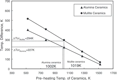
Figure 1 shows the relation between the maximum temperature difference and preheating temperature, which also includes Tcr. The figure indicates that the critical
preheating temperature appropriate for compo-casting of the ceramic is 1002 K for alumina ceramics and 1019 K for mullite ceramics. These estimated values are some 250 K lower than 1273 K which is the critical preheating temper-ature obtained by the experiments. This lower estimation should result from the temperature drop of the ceramic body during the poring operation, which means that the temper-ature of the ceramics was assumed to be same as the preheating temperature in the experiment but it might have dropped some 200 K until the molten metal touched the ceramic body. Although the estimation results were some-what lower than those from the experiments, the estimation method that combines the thermal stress analysis during transient thermal conduction and Newman’s diagram, which are obtained from the transient thermal conduction equation is a useful way to estimate the critical preheating temperature in compo-casting of ceramics body.
3. Compo-casting of Ceramics Using a Cast Iron Cover
3.1 Estimation of appropriate thickness of a cast iron cover for compo-casting without preheating of ceramics
As already mentioned, we can successfully perform the ceramics/cast iron compo-casting if we preheat the ceramics over the temperature determined by the thermal stress analysis based on an transient thermal conduction model and Newman’s diagram. However, the preheating temper-ature can be as high as 1273 K and it is also not easy to maintain this temperature after preheating until the pouring period, therefore, it appears not applicable for practical production. We then studied a new compo-casting method which requires no-preheating of the ceramic body. We tried to put a cast iron cover over the ceramic body to relieve the thermal shock of the ceramics. In order to prevent the generation of cracks in a ceramic body, the temperature difference between the surface and center should be less than
Tmax. We then applied the thermal stress analysis during
transient thermal conduction and Newman’s diagram used above to estimate the appropriate thickness of the cast iron cover which makes the temperature difference between the surface and center of the ceramics less thanTmax.
At first, the temperature of the internal surface of the cover whose outer surface is heated by a melt is calculated using eqs. (1), (2) and (3). The temperatures at the surface and the center of the ceramic body whose surface is heated by thermal conduction through the internal surface of the cover are then calculated using eqs. (1), (2) and (3). In the calculations, we assumed the following variables: the radius of the ceramics (rceramics) is 0.005 m, the temperature of the
fluid (= pouring temperature) (Tf) is 1653 K and the heat
conductivity (h) is 3:0103W/(m2K). The analysis was performed for every 0.001 m in thickness of the cast iron cover (rmetals). Figure 2 shows the analysis results for the
relation between the thickness of the cover and the temper-ature difference between the surface and center of the ceramics. This result indicates that the necessary thickness to make the temperature difference less thanTmax is 6.7 and
7.3 mm for the alumina ceramics and mullite ceramics, respectively. Therefore, we decided to use the cast iron cover whose thickness is 7 and 8 mm for the alumina ceramics and mullite ceramics, respectively, in our experiments. Figure 3 shows the relation between the time and temperatures of the surface and center for the 7 mm thick cover for the alumina ceramics, and it also shows the temperature difference between them. This figure indicates that the maximum temperature difference between them is 208 K, which is less than 227 K of itsTmax. This means that a 7 mm thick cover
is considered to be effective to sufficiently relieve the thermal shock in the ceramic body.
3.2 Experimental procedures
The ceramic materials included alumina and mullite ceramics whose chemical composition and physical proper-ties are shown in Table 1, and the dimensions of the ceramic body for compo-casting is a cylindrical bar with a 10 mm diameter and 25 mm length. The cast iron material for compo-casting is a flake graphite cast iron equivalent to 0 100 200 300 400 500 600 700
300 500 700 900 1100 1300 1500 1700
Alumina Ceramics Mullite Ceramics Alumina ceramics 1002K Mullite ceramics 1019K
∆TcrMullite=294K
∆TcrAlumina=227K
Pre−heating Temp. of Ceramics, K
Temp. Difference, K
[image:2.595.56.284.591.746.2]FC150. The cast iron cover is also made of FC150, and its shape is a hollow cylindrical bar type with one end closed with a cylindrical hole of 10 mm diameter and 15 mm depth, and the wall thickness is 7 or 8 mm. The mold for compo-casting is made of CO2sand and has a cylindrical hole with a 100 mm diameter and 150 mm depth. A ceramic body was placed in the center of the bottom surface with a 10 mm depth and tightly covered with the cast iron cover. The molten metal was heated to 1723 K and kept for 0.6 ks in an induction furnace, and then poured into the mold at 1653 K. Based on our calculation of Tmax as previously
men-tioned, we assumed that the temperature of the melt is constant and the heat capacity of the melt was not included. Therefore, in order to clarify the effect of the heat capacity of the melt, we varied the amount of melt from 1.5 to 4.0 kg in 0.5 kg step. The specimen (product of compo-casting) was cut into two along the center line by a diamond cutter, and its cutting plane was precisely examined by an optical micro-scope.
3.3 Experimental results and discussions
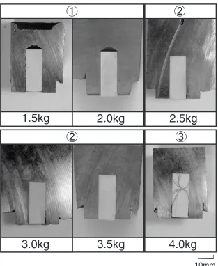
Figure 4 shows the cutting planes of the specimens of the alumina ceramics and 7 mm thick cast iron cover. The results may be classified into the 3 following grades:
[Grade 1] For the 1.5 kg melt, no crack is observed but a gap (opening) is observed between the ceramics and metal at the top and the side. The shape of the opening at the top exhibits a trace of the drill hole, which means that the cast iron cover has not yet completely melted. Adding to this, the ceramics
separates from the metal.
[Grade 2] For the 2.0, 2.5 and 3.0 kg melts, no crack or gap is recognized, which means that excellent compo-casting results are obtained.
[image:3.595.55.285.72.201.2][Grade 3] For the 3.5 and 4.0 kg melts, no gap is observed, but cracks are recognized in the ceramics, and the cracks are recognized to be filled with metal, which means that the cast iron cover has completely melted. Though the ceramics has cracks, its bonding is excellent.
Figure 5 shows some examples of the microstructure of the interface area between the cast iron cover and cast metal. For the 1.5 kg melt, the size of the graphite flakes on the melt side (right) is much smaller than that of the cast iron cover side (left), which means that the melt solidified very quickly near the surface area of the cover. Also, as a clear boundary line is observed between the two sides, the cover has not yet melted. For the 2.5 kg melt, the microstructures of both sides are almost the same and no boundary line is recognized, which means that the cover has completely melted and has combined with the melt. Figure 6 shows a schematic illustration of the evaluated results mentioned above. In the figure, the bottom line of each ceramic denotes the very bottom line of the ceramic body which had been buried in the sand mold, which means that the gap lines (thick solid lines) for the 2.0 to 3.5 kg melts are located beneath the bottom surface of the mold.
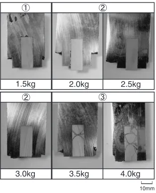
Figure 7 shows the experimental results of compo-casting with mullite ceramics using 8 mm thick cast iron covers. Similar to that of the alumina ceramics, the results of the mullite ceramics may be classified into the 3 grades mentioned below.
[Grade 1] For the 1.5 and 2.0 kg melts, no crack is observed, but a small gap is seen between the ceramics and metal at the top and the side.
[Grade 2] For the 2.5, 3.0 and 3.5 kg melts, no crack or gap is observed, which means that excellent compo-casting results are obtained.
[Grade 3] For the 4.0 kg of melts, no gap is observed, but cracks are observed in the ceramics and the cracks are filled with metal.
3.4 Influence of amount of melt on generation of cracks The results mentioned above indicate that the generation of
Table 1 Chemical composition and properties of ceramics used.
Alumina Mullite
Al2O3 95 mass% 56 mass%
SiO2 3 mass% 40 mass%
Bulk density 3.7 g/cm3 2.6 g/cm3
Compressive strength 2000 MPa 1300 MPa
Bending strength Room temp. 250 MPa 160 MPa
1473 K 80 MPa 90 MPa
Thermal conductivity (673 K) 21 W/(mK) 3.4 W/(mK)
Coefficient of thermal expansion
(293–1273 K) 7:810
6K1 4:9106K1
Highest use temp. 1973 K 2123 K
Electrical resistivity Room temp. >10
13cm >1013cm
773 K 105cm 5:0105cm
0 50 100 150 200 250 300 350 400
5 6 7 8 9 10
Cover thickness , mm
Maximum temperature difference, K
Alumina ceramics Mullite ceramics
Pouring Temp:1653K
TcrMullite= 294K
Alumina= 227K
Tcr
Fig. 2 Calculated thickness of cast iron covers prevent cracking in ceramics. 0 200 400 600 800 1000 1200 1400
0 2 4 6 8 10
Time:S
Temperature
:
K
Surface of the ceramic Center of the ceramic Temp. difference
208K
[image:3.595.304.550.83.262.2] [image:3.595.56.284.260.390.2]cracks is mostly related to the amount of the melt for compo-casting. Our calculation method is useful for estimating
Tmax, but the influence of the melt’s heat capacity should be
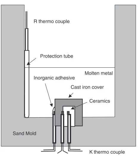
taken into account for a more accurate estimation. Therefore, we tried to measure the actual temperatures at three places in a specimen. Figure 8 shows the three places where the thermocouples (Type K, 0.5 mm diameter) were located
using an inorganic adhesive: one is on the surface of the cast iron cover and the other two are on the center and surface of the ceramic body. The temperature of the melt is measured by a thermocouple (Type R, 0.5 mm diameter) which is located on the surface of the mold. The method of compo-casting was the same as the method described in section 3.2, and the amounts of the melts were varied from 1.5, 2.5 and 4.0 kg.
2.5kg
100µm1.5kg
Fig. 5 Microstructures near the interface of molten metal and the cast iron cover (7 mm).
1.5kg
2.0kg
2.5kg
3.0kg
3.5kg
4.0kg
10mm
[image:4.595.142.456.69.458.2] [image:4.595.115.485.500.659.2]1.5kg
2.0kg
2.5kg
3.0kg
3.5kg
4.0kg
10mm
Fig. 7 Experimental results of compo-casting with mullite ceramics using cast iron covers (8 mm).
1.5kg
2.0kg
2.5kg
3.0kg
3.5kg
4.0kg
Gap
Crack
Cast iron
Ceramic
This par
t which had
been b
u
ried in sand mold.
[image:5.595.143.453.78.343.2] [image:5.595.142.455.380.762.2]Figure 9 shows the results of the measurements. For the 1.5 kg melt, the temperature increase of the surface and the center of the ceramics are the lowest among all the three diagrams, and the temperature difference between the surface and center of the ceramics are also the lowest of all. The maximum temperature difference is 144 K, which is much smaller than Tmax (¼227K), and means that no crack is
generated. For the 2.5 kg melt, the temperature increases in the ceramics become higher than those of the 1.5 kg case, which results in a greatest temperature difference between them. The maximum temperature difference is 259 K, which is nearTmax, but no crack is generated. For the 4.0 kg melt,
the changes and the temperature difference become much higher than the case of 2.5 kg case, and the maximum temperature is as high as 499 K, which is much higher than
Tmax, and cracks are generated. Though some experimental
errors such as the response-delay caused by the thermocouple protection tubes and heat capacity of the thermocouple itself might have produced some inaccuracies in the diagrams, the tendencies observed in these diagrams are considered to coincide well with the results of our estimations and the experiments. For the mullite ceramics, tendencies very similar to those of the alumina ceramics were also observed. For a smaller amount of melt, the temperature of the melt significantly drops when the melt touches the cast iron cover, and the cover does not sufficiently melt and a gap occurs between the ceramics and metal. However, for a large amount of melt, the temperature drop of the melt becomes much smaller so that the cover melts, which means that the temperature of the ceramics surface rapidly rises and the temperature difference between the surface and center expands largely and the cracks are generated.
The results obtained so far indicate that the amount of melt affects the temperature drop of the melt. This temperature
drop of the melt may be one of the main causes that produced some different results between the experiments and estima-tion which assumes that the temperature of the melt is constant. Adding to this, Newman’s diagram deals only with the thermal conductivity in the radius direction, but the heat transfer from the top surface side of ceramic body is not included in this experiment. Therefore, we need to consider the most appropriate amount of melt for a given thickness of the cast iron cover. In order to examine the appropriateness of the thickness of the cover which we applied in this study, we performed some additional experiments with a thinner cover and smaller amount of melt than those of the experiments which we have already done. In this experiment, we used 3.5 and 4.4 mm thick cast iron covers, the former is 1/2 the thickness (7 mm) of the previous cover for the alumina ceramics and the latter is a thickness whose cover has 1/2 the volume of that of the previous cover. Figure 10 shows the results of these experiments. When we used the 3.5 mm thick cover, no crack was generated but gaps (openings) were observed between the ceramics and metal for the 1.5 kg melt, and cracks were generated and filled with melt for the 2.0 kg and 2.5 kg melts. These results are ranked as ‘‘Grade 1’’ and ‘‘Grade 3’’ as described in section 3.3. When we used the 4.4 mm thick cover, no cracks, but gaps were observed for the 1.5 kg melt, and both cracks and gaps were observed for the 2.0 kg, and cracks were generated and filled with melt for the R thermo couple
Protection tube
K thermo couple Molten metal
Cast iron cover
Ceramics
Sand Mold
Inorganic adhesive
Fig. 8 Schematic view of the temperature measuring positions in the sand mold. 300 600 900 1200 1500 1800
0 20 40 60 80 100
Time, s
Temperature, K Maximum temp. difference : 144K
Center of ceramics
300 600 900 1200 1500 1800
0 20 40 60 80 100
Time, S
Tempereture, K Maximum temp. difference : 259K
300 600 900 1200 1500 1800
0 20 40 60 80 100
Time, S
Temperature, K
Surface of cover Molten metal
Maximum temp. difference : 499K
Pouring Weight 4.0kg Pouring Weight 2.5kg Pouring Weight 1.5kg
Surface of ceramics
[image:6.595.314.540.74.421.2]2.5 kg melt. In the experiments with the 3.5 mm thick or 4.4 mm thick cast iron covers, we could not obtain any good result which meets the ‘‘Grade 2’’ (no crack and no gap) described in section 3.3.
These results indicate that the appropriate thickness required to get good compo-casting results should be considered from the view points of a sufficient absorption of heat to melt the cover itself, sufficient relief ability for thermal shock of the ceramics body and sufficient contact between the ceramics and melt.
From these view points, the Newman’s diagram that was used for the thermal stress analysis is considered to be helpful.
4. Conclusion
Using a thermal stress analysis of transient heat transfer, we tried to obtain the critical temperature difference for the generation of cracks during the compo-casting of ceramics with cast iron. From Newman’s diagram, we obtained the most appropriate heating conditions to relieve the thermal shock of the ceramics. We also tried to minimize the thermal shock of the ceramics using a cast iron cover whose thickness
had been estimated from Newman’s diagram, and we could successfully perform the compo-casting of ceramics with cast iron without the preheating of the ceramics. The results obtained are summarized as follows.
(1) The critical temperature difference between the surface and center of a ceramics body for the generation of cracks can be obtained from the thermal stress analysis of transient thermal conduction and Newman’s dia-gram.
(2) We recognized that a cast iron cover reduces the temperature difference, and the compo-casting of ceramics without preheating is possible if a cast iron cover is used. We estimated the appropriate thickness of the cover from the thermal stress analysis of transient thermal conduction and Newman’s diagram, and determined a 7 mm thick alumina ceramics and an 8 mm thick mullite ceramics for our experimental conditions. Using the cast iron cover and between 2.5 and 3.0 kg melts, we successfully performed the compo-casting of ceramics.
(3) The appropriate thickness required to get good compo-casting results should be considered from the view points of the sufficient absorption of heat to melt the
10mm
Thickness of cover : 3.5mm
Thickness of cover : 4.4mm
1.5kg
2.0kg
2.5kg
1.5kg
2.0kg
2.5kg
[image:7.595.140.455.72.465.2]10mm
cover itself, sufficient relief ability from the thermal shock of the ceramic body and sufficient contact between the ceramics and melt. Newman’s diagrams along with the thermal conduction equation are useful to estimate the appropriate thickness, and our estima-tion results agree well with the experimental results. However, the amount of melt was also found to affect the generation of cracks due to its heat capacity. This study was discussed at The Technology Presiding Committee for Structure Improvement (Chairman: Dr. Kokichi Nakamura, Honorary Professor of Kinki University) of the Japan Cast Iron Foundry Association.
REFERENCES
1) K. Sakai, A. Mizuta and S. Okazaki: J. JFS.68(1996) 488. 2) T. Hayakawa: Materia Japan42(2003) 461.
3) T. Noguchi, K. Noguchi, J. Ohmori, S. Kamoda and K. Shimizu: J. JFS. 70(1998) 247.
4) K. Ogi: J. JFS.68(1996) 1050.
5) N. Horikawa, T. Itou, L. S. Wang, T. Noguchi and S. Kamota: J. JFS.73
(2001) 668.
6) K. Okada, S. Idetsu, S. Goto, S. Aso and Y. Komatsu: J. JFS.73(2001) 493.
7) M. Tsujikawa, S. Nakabori, M. Hino, A. Ikenaga and M. Kawamoto: J. JFS.75(2003) 532.
8) T. Tsujimura and T. Miyauchi: Combining and Making to High Performance of Cast Iron(Japan Society for the Promotion of Science: The 24th Committee Cast Iron Section Association of Cast Metals) (2002) p. 279.
9) Y. Takahashi, K. Shimizu, M. Adachi, K. Ogi and S. Katagishie: Proceedings of the 7th Asian Foundry Congress-Taipei, Taiwan (2001) p. 25.
10) Y. Tomita, H. Sumimoto, S. Kiguchi and K. Nakamura: J. JFS.74 (2002) 143.
11) Japan Society Of Mechanical Engineers: The Fourth Heat Trans-mission Engineering Material Revision Edition (Japan Society of Mechanical Engineers) (1987) p. 7.
12) M. Shouji: Heat Transmission Engineering (University of Tokyo Publication Association) (1995) p. 143.
13) Machine Design Handbook Edit Committee:Machine Design Hand-book(Maruzen, 1958) p. 1635.
14) J. Chigira: Heat Transmission Calculation Method (Engineering Books, 1981) p. 193.